2001 DODGE RAM steering
[x] Cancel search: steeringPage 2828 of 2889
Items found requiring adjustment and/or repair
should be corrected before delivery of the vehicle.
NOTE: It is the dealer's responsibility to protect
new vehicles from damage and deterioration prior
to retail delivery both before and after new vehicle
preparation.
The information includes the following features:
Inspection points are cross-referenced to the New
Vehicle Preparation Form as follows:
²Titles indicate the general area being inspected
or the types of checks being made (i.e., underhood,
body-exterior, road test, etc.).
²Sub-Titles identify the types of items to be
inspected in that area (i.e., lines/hoses, wiring, etc.).
Procedures follow a logical order to prevent dupli-
cation and wasted effort.
Tips to help you do a better job are found as
NOTES.
RECEIVING
INSPECTION
The following procedures are recommended for
your own protection upon receipt of new vehicles.
When a new car is delivered by the carrier, it should
be inspected to ensure that it is in good condition
and to determine if there is any shortage or transpor-
tation damage.
EXTERIOR
Upon receipt of a new vehicle, check immediately
for:
²Under carriage damage
²Chipped or cracked windshield, broken windows,
and loose or missing moldings and name-plates
²Dents, scrapes, scratches, chips, dirt in paints or
other damage to the body exterior
²Damaged or missing side view mirror(s)
²Missing wheel nuts
²Broken or missing lenses
²Chafing, bruises, cuts, or scrapes on tire side-
walls or tread
²Missing underhood items
²Missing fuel filler cap
²Shipped loose items-license plate bracket, spare
tire, jack and tire wrench, radio antenna, floor mats,
wheel covers, cargo nets, fuses and other items²Ensure that IOD fuse is removed
²Check battery test indicator when easily visible,
or use voltmeter (battery must be at 12.4 volts or
greater). Charge to ensure green dot-visibility, per-
manent damage may occur if battery remains in a
discharged state for any length of time.
INTERIOR
Check interior items such as:
²Rearview mirror
²Accessory control knobs
²Smokers package items
²Keys
²Radio
²Special equipment items listed on shipper
²Owner's Manual and Consumer information Bro-
chures (normally stored in the glove box).
²Cuts, abrasions or stains on interior trim.
NOTE: Remember a careful look at new vehicles
when they are received may prevent problems when
preparing vehicles for delivery to your customers.
MAJOR INSPECTION POINTS
(1) Check operation of hood latch and safety catch-
adjust as required.
(2) Check all fluids for proper level and top off
with the proper fluid as required-engine oil, auto-
matic transmission fluid, brake master cylinder,
clutch master cylinder, power steering, windshield
washer, and cooling system. (Vehicle must be at nor-
mal operating temperature for some of these checks.)
(3) Check brake, clutch, fuel, and power steering
lines and hoses for leaks and clearance from moving
and hot objects-reroute to the proper location and
tighten as required.
(4) Check battery state of charge-recharge if neces-
sary, to ensure green dot is visible or instrument
panel voltmeter indicates 12.4 volts or greater.
(5) Check routing and connections of underhood
wiring, vacuum hoses, refrigerant lines and coolant
hoses for leaks, loose connections and clearance from
moving objects reroute and tighten connections as
required. Install IOD fuse on applicable vehicles.
NOTE: Reset radio, clock, compass, etc., after
installing, if vehicle is being delivered.
BR/BENEW VEHICLE PREPARATION 30 - 3
INTRODUCTION (Continued)
Page 2830 of 2889
BRAKE MASTER CYLINDER
CAUTION: Only use fluid that meets specified
requirements (DOT 3).
NOTE: Wipe the master cylinder cover to remove
any dirt.
NOTE: On vehicles equipped with remote antilock
brakes, the fluid level check is the same as for a
normal system.
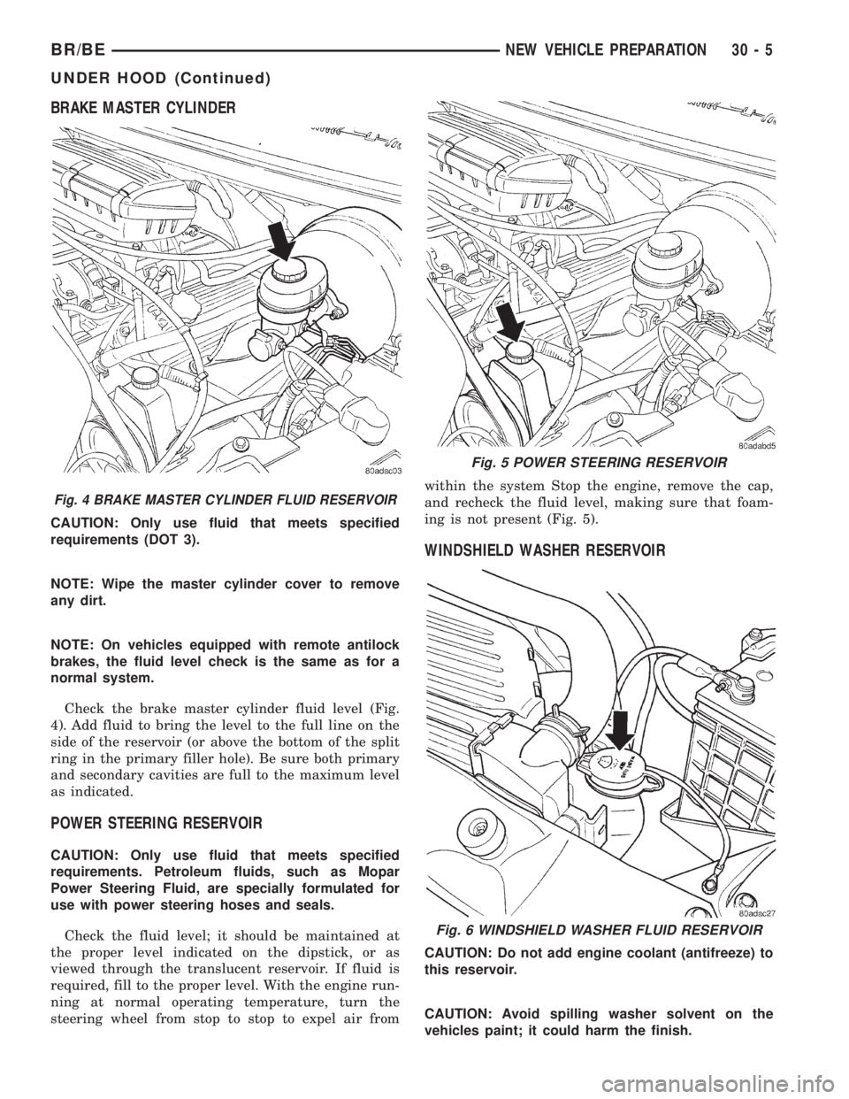
Check the brake master cylinder fluid level (Fig.
4). Add fluid to bring the level to the full line on the
side of the reservoir (or above the bottom of the split
ring in the primary filler hole). Be sure both primary
and secondary cavities are full to the maximum level
as indicated.
POWER STEERING RESERVOIR
CAUTION: Only use fluid that meets specified
requirements. Petroleum fluids, such as Mopar
Power Steering Fluid, are specially formulated for
use with power steering hoses and seals.
Check the fluid level; it should be maintained at
the proper level indicated on the dipstick, or as
viewed through the translucent reservoir. If fluid is
required, fill to the proper level. With the engine run-
ning at normal operating temperature, turn the
steering wheel from stop to stop to expel air fromwithin the system Stop the engine, remove the cap,
and recheck the fluid level, making sure that foam-
ing is not present (Fig. 5).
WINDSHIELD WASHER RESERVOIR
CAUTION: Do not add engine coolant (antifreeze) to
this reservoir.
CAUTION: Avoid spilling washer solvent on the
vehicles paint; it could harm the finish.
Fig. 4 BRAKE MASTER CYLINDER FLUID RESERVOIR
Fig. 5 POWER STEERING RESERVOIR
Fig. 6 WINDSHIELD WASHER FLUID RESERVOIR
BR/BENEW VEHICLE PREPARATION 30 - 5
UNDER HOOD (Continued)
Page 2831 of 2889
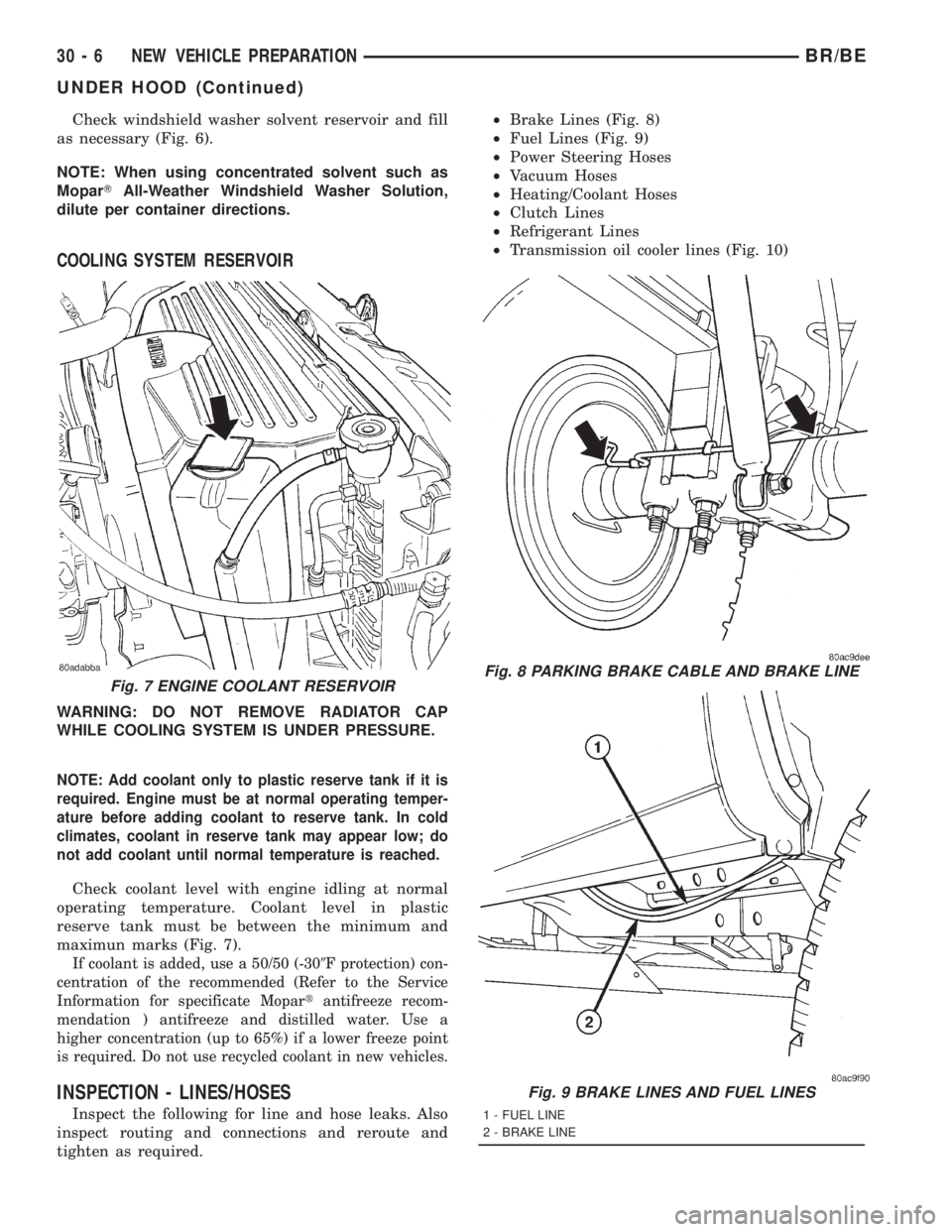
Check windshield washer solvent reservoir and fill
as necessary (Fig. 6).
NOTE: When using concentrated solvent such as
MoparTAll-Weather Windshield Washer Solution,
dilute per container directions.
COOLING SYSTEM RESERVOIR
WARNING: DO NOT REMOVE RADIATOR CAP
WHILE COOLING SYSTEM IS UNDER PRESSURE.
NOTE: Add coolant only to plastic reserve tank if it is
required. Engine must be at normal operating temper-
ature before adding coolant to reserve tank. In cold
climates, coolant in reserve tank may appear low; do
not add coolant until normal temperature is reached.
Check coolant level with engine idling at normal
operating temperature. Coolant level in plastic
reserve tank must be between the minimum and
maximun marks (Fig. 7).
If coolant is added, use a 50/50 (-309F protection) con-
centration of the recommended (Refer to the Service
Information for specificate Mopartantifreeze recom-
mendation ) antifreeze and distilled water. Use a
higher concentration (up to 65%) if a lower freeze point
is required. Do not use recycled coolant in new vehicles.
INSPECTION - LINES/HOSES
Inspect the following for line and hose leaks. Also
inspect routing and connections and reroute and
tighten as required.²Brake Lines (Fig. 8)
²Fuel Lines (Fig. 9)
²Power Steering Hoses
²Vacuum Hoses
²Heating/Coolant Hoses
²Clutch Lines
²Refrigerant Lines
²Transmission oil cooler lines (Fig. 10)
Fig. 7 ENGINE COOLANT RESERVOIRFig. 8 PARKING BRAKE CABLE AND BRAKE LINE
Fig. 9 BRAKE LINES AND FUEL LINES
1 - FUEL LINE
2 - BRAKE LINE
30 - 6 NEW VEHICLE PREPARATIONBR/BE
UNDER HOOD (Continued)
Page 2833 of 2889
UNDER VEHICLE
INSPECTION - TIRE PRESSURES
(1) Using the tire placard or the Safety Certifica-
tion Label, check that the correct tires are mounted
on the vehicle.
(2) Install valve stem extensions as required.
(3) Using the tire placard or the Safety Certifica-
tion Label, check tire pressure (including spare) and
adjust as required to recommended pressure.
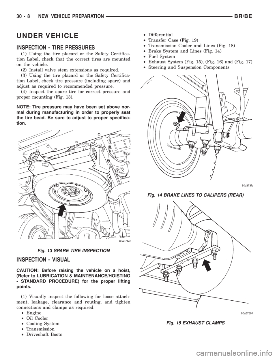
(4) Inspect the spare tire for correct pressure and
proper mounting (Fig. 13).
NOTE: Tire pressure may have been set above nor-
mal during manufacturing in order to properly seat
the tire bead. Be sure to adjust to proper specifica-
tion.
INSPECTION - VISUAL
CAUTION: Before raising the vehicle on a hoist,
(Refer to LUBRICATION & MAINTENANCE/HOISTING
- STANDARD PROCEDURE) for the proper lifting
points.
(1) Visually inspect the following for loose attach-
ment, leakage, clearance and routing, and tighten
connections and clamps as required:
²Engine
²Oil Cooler
²Cooling System
²Transmission
²Driveshaft Boots²Differential
²Transfer Case (Fig. 19)
²Transmission Cooler and Lines (Fig. 18)
²Brake System and Lines (Fig. 14)
²Fuel System
²Exhaust System (Fig. 15), (Fig. 16) and (Fig. 17)
²Steering and Suspension Components
Fig. 13 SPARE TIRE INSPECTION
Fig. 14 BRAKE LINES TO CALIPERS (REAR)
Fig. 15 EXHAUST CLAMPS
30 - 8 NEW VEHICLE PREPARATIONBR/BE
Page 2840 of 2889
ROAD TEST
DESCRIPTION - ROAD TEST INSPECTION
The following items must be inspected during the
road test portion of the new vehicle inspection.
²Check neutral safety switch operation
²Check operation of shift/clutch interlock system
²Check operation of gauges and warning lights
²Check horn operation
²Check operation of turn signals and emergency
flashers
²Check all mirror adjustments, including day/
night function
²Check windshield wipers for proper wipe pattern
and intermittent mode (if equipped)
²Check washer spray pattern
²Check heater, defroster and air conditioning for
proper operation
²Check that the fan operates quietly
²Check the rear window defroster (if equipped)
²Leave air selection lever in the fresh air position
²Check the rear heater and air conditioning for
proper operation
²Check the rear air register locations
²Check that the indicator lamps operate properly
²Check the operation of the radio, cassette and/or
compact disc player, and that sound quality is good
²Ensure that the clock displays the correct time
²Check that the trip computer/maintenance
reminder operates in all modes
²Check all speed control functions
²Check the service brakes to ensure that they
stop the vehicle in a straight line, without noise,
shudder or vibration
²Check the brake warning light
²Check the parking brake operation
²Check the engine's performance
²Check the transmission's performance for
smooth, quiet operation. If the vehicle is a 4x4, check
that the transfer case shifts easily among all ranges
²Check Autostick function (if equipped)
²Check the vehicle's steering and handling
²The steering wheel should be centered when
traveling in a straight line
²The vehicle should not pull or vibrate
²Check for squeaks, rattles and wind noise
²Check any other vehicle aspects you believe are
important, but that may not be included on the New
Vehicle Preparation Form
²Fill fuel tank with specified grade of fuel
INSPECTION - FUEL
Fill fuel tank with specified grade of gasoline (reg-
ular, midgrade or premium).
INSPECTION - OTHER
As part of DaimlerChrysler's Customer One philos-
ophy, the ªOtherº blank is provided on the New Vehi-
cle Preparation Form. This is designed to encourage
you to check any aspects of vehicle operation that
you believe are important to your customers, but that
do not appear elsewhere on the form.
INSPECTION - SQUEAKS, RATTLES AND WIND
NOISE
(1) Make sure that the instrument panel, glove
box, seats, steering wheel and column are free from
squeaks and rattles. Tighten any obvious loose fas-
teners.
(2) Check that the windows and doors are free
from squeaks, rattles and wind noise.
(3) Check that the vehicle exterior is free from
squeaks, rattles and noise, front and rear.
(4) Make sure that all interior panels are free from
squeaks and rattles.
INSPECTION - STEERING AND HANDLING
(1) Check that the power assist works properly (if
equipped). Steering should not require excessive
effort.
(2) Make sure the steering wheel does not vibrate
at idle or road speed.
(3) Ensure that the steering wheel is centered
when traveling straight ahead.
(4) Check that the vehicle does not drift to one
side.
(5) Make sure that the vehicle does not vibrate/
shake.
INSPECTION - TRANSMISSION/TRANSFER
CASE
AUTOMATIC TRANSMISSION
(1) Make sure that the park lock holds the vehicle
With the vehicle on a grade, put automatic trans-
mission in PARK and slowly release the service
brake to see if park lock holds. If it does not hold, the
transmission requires further service.
(2) Make sure shift lever operates easily/ smoothly
(Fig. 36).
Check for smooth shifting. Check for proper
upshifting and downshifting.
MANUAL TRANSMISSION
(1) Check that the shifter operates easily (Fig. 38).
(2) Make sure that the clutch operates smoothly
(Fig. 37).
(3) Look for proper synchronization.
The gears should not grind.
BR/BENEW VEHICLE PREPARATION 30 - 15
Page 2842 of 2889
INSPECTION - PARKING BRAKE
(1) Ensure that the parking brake is easy to oper-
ate (Fig. 40).
(2) Make sure the parking brake does not drag.
(3) With the vehicle stopped on a grade, firmly
apply the service brakes, place the transmission in
NEUTRAL and set the parking brake. Slowly release
the service brakes to see if the parking brake will
hold.
(4) Check that the parking brake warning light
comes on when the parking brake is applied, and is
off when the brake is released.
INSPECTION - SERVICE BRAKES
(1) Check brake warning light operation at vehicle
startup.
(2) Check ABS warning light operation at vehicle
startup.
(3) Inspect service brake pedal travel and feel (Fig.
41).
(4) Put the vehicle in gear and apply the brakes
while the car is in motion. Be sure brake operation is
smooth and positive.
(5) Make sure that the vehicle stops in a straight
line, without pulling to one side.
(6) Check that the brakes operate quietly, without
noise.
(7) Ensure there is no shudder or vibration when
braking.
INSPECTION - SPEED CONTROL
Check the following speed control functions (Fig.
42):²Check on/off switch
²Check ªsetº operation
²Check ªresumeº function
²Check ªaccelerateº and ªdecelerateº functions
²Check brake release function
²Check ªcancelº function
INSPECTION - TRIP COMPUTER/
MAINTENANCE REMINDER
NOTE: Reset the average fuel economy when the
road test is complete.
Check that all modes operate correctly (Fig. 43).
INSPECTION - RADIO
(1) Check for good AM/FM reception, ensure that
the cassette and/or compact disc (CD) player works
properly (Fig. 44).
(2) Check for good sound quality from all speakers.
(3) Ensure that the radio displays the correct time.
(4) Check the steering wheel controls (if equipped).
INSPECTION - HEATER/AIR CONDITIONER
(1) Check that heater/defroster works properly
(Fig. 45).
(2) Turn on the heater when the engine reaches
operating temperature.
(3) Operate the blower motor in all speeds.
(4) Operate system in all modes (heat, defrost,
etc.).
(5) Operate the rear heater (if equipped).
(6) Check for hot air output at all outlets.
Fig. 40 PARKING BRAKE OPERATION
Fig. 41 SERVICE BRAKE PEDAL
BR/BENEW VEHICLE PREPARATION 30 - 17
ROAD TEST (Continued)
Page 2855 of 2889
CLUTCH RELAY - DIAGNOSIS AND
TESTING, A/C COMPRESSOR...........24-17
CLUTCH RELAY - INSTALLATION, A/C
COMPRESSOR.......................24-18
CLUTCH RELAY - OPERATION, A/C
COMPRESSOR.......................24-17
CLUTCH RELAY - REMOVAL, A/C
COMPRESSOR.......................24-18
CLUTCH RELEASE BEARING -
DESCRIPTION........................6-14
CLUTCH RELEASE BEARING -
INSTALLATION........................6-15
CLUTCH RELEASE BEARING -
OPERATION..........................6-14
CLUTCH RELEASE BEARING - REMOVAL . . . 6-15
COAT FINISH - DESCRIPTION, BASE
COAT/CLEAR.......................23-129
COAT FINISH - OPERATION, BASE
COAT/CLEAR.......................23-129
COAT HOOK - INSTALLATION..........23-125
COAT HOOK - REMOVAL..............23-124
COAT/CLEAR COAT FINISH -
DESCRIPTION, BASE.................23-129
COAT/CLEAR COAT FINISH - OPERATION,
BASE.............................23-129
CODE - DESCRIPTION, PAINT..........23-129
CODE PLATE - DESCRIPTION, BODY....Intro.-1
CODES - DESCRIPTION, DIAGNOSTIC
TROUBLE............................25-2
CODES, SPECIFICATIONS - 2001 BR
PAINT COLOR......................23-129
COIL - DIAGNOSIS AND TESTING, A/C
COMPRESSOR CLUTCH...............24-13
COIL RESISTANCE, 3.9L/5.2L/5.9L
ENGINES - IGNITION...................8I-3
COIL RESISTANCE, 8.0L V-10 ENGINE -
IGNITION............................8I-3
COLOR CODES, SPECIFICATIONS - 2001
BR PAINT..........................23-129
COLUMN - DESCRIPTION...............19-6
COLUMN - INSTALLATION...............19-8
COLUMN - REMOVAL..................19-7
COLUMN - SERVICE PRECAUTIONS.......19-6
COLUMN OPENING COVER -
INSTALLATION, STEERING............23-116
COLUMN OPENING COVER - REMOVAL,
STEERING.........................23-115
COMBINATION FLASHER - DESCRIPTION . . . 8L-7
COMBINATION FLASHER -
INSTALLATION........................8L-8
COMBINATION FLASHER - OPERATION....8L-7
COMBINATION FLASHER - REMOVAL......8L-8
COMBINATION VALVE - DESCRIPTION......5-9
COMBINATION VALVE - DIAGNOSIS AND
TESTING.............................5-9
COMBINATION VALVE - INSTALLATION.....5-10
COMBINATION VALVE - OPERATION........5-9
COMBINATION VALVE - REMOVAL........5-10
COMBUSTION PRESSURE LEAKAGE -
DIAGNOSIS AND TESTING, CYLINDER....9-124,
9-179,9-67,9-9
COMPASS - INSPECTION..............30-12
COMPASS CALIBRATION - STANDARD
PROCEDURE.........................8M-4
COMPASS DEMAGNETIZING -
STANDARD PROCEDURE...............8M-5
COMPASS MINI-TRIP COMPUTER -
DIAGNOSIS & TESTING...............8M-10
COMPASS VARIATION ADJUSTMENT -
STANDARD PROCEDURE...............8M-4
COMPASS/MINI-TRIP COMPUTER -
DESCRIPTION........................8M-8
COMPASS/MINI-TRIP COMPUTER -
INSTALLATION......................8M-11
COMPASS/MINI-TRIP COMPUTER -
OPERATION.........................8M-9
COMPASS/MINI-TRIP COMPUTER -
REMOVAL..........................8M-11
COMPRESSION PRESSURE - DIAGNOSIS
AND TESTING, CYLINDER . . 9-124,9-179,9-67,9-9
COMPRESSOR - DESCRIPTION, A/C......24-46
COMPRESSOR - DIAGNOSIS AND
TESTING, A/C
.......................24-46
COMPRESSOR - INSTALLATION, A/C
.....24-47
COMPRESSOR - OPERATION, A/C
........24-46
COMPRESSOR - REMOVAL, A/C
.........24-47
COMPRESSOR CLUTCH - DESCRIPTION,
A/C
................................24-13COMPRESSOR CLUTCH - INSPECTION,
A/C................................24-16
COMPRESSOR CLUTCH - INSTALLATION,
A/C................................24-16
COMPRESSOR CLUTCH - OPERATION,
A/C................................24-13
COMPRESSOR CLUTCH - REMOVAL, A/C . . 24-14
COMPRESSOR CLUTCH BREAK-IN -
STANDARD PROCEDURE, A/C...........24-13
COMPRESSOR CLUTCH COIL -
DIAGNOSIS AND TESTING, A/C..........24-13
COMPRESSOR CLUTCH RELAY -
DESCRIPTION, A/C...................24-17
COMPRESSOR CLUTCH RELAY -
DIAGNOSIS AND TESTING, A/C..........24-17
COMPRESSOR CLUTCH RELAY -
INSTALLATION, A/C...................24-18
COMPRESSOR CLUTCH RELAY -
OPERATION, A/C.....................24-17
COMPRESSOR CLUTCH RELAY -
REMOVAL, A/C......................24-18
COMPUTER - DESCRIPTION, COMPASS/
MINI-TRIP..........................8M-8
COMPUTER - DIAGNOSIS & TESTING,
COMPASS MINI-TRIP.................8M-10
COMPUTER - INSTALLATION, COMPASS/
MINI-TRIP.........................8M-11
COMPUTER - OPERATION, COMPASS/
MINI-TRIP..........................8M-9
COMPUTER - REMOVAL, COMPASS/
MINI-TRIP.........................8M-11
COMPUTER/MAINTENANCE REMINDER -
INSPECTION, TRIP...................30-17
CONDENSER - DESCRIPTION, A/C.......24-48
CONDENSER - INSTALLATION, A/C.......24-49
CONDENSER - OPERATION, A/C.........24-48
CONDENSER - REMOVAL, A/C..........24-49
CONDITIONER - DESCRIPTION, HEATER
AND AIR ............................24-1
CONDITIONER - INSPECTION,
HEATER/AIR.........................30-17
CONDITIONER - OPERATION, HEATER
AND AIR ............................24-1
CONDITIONING - INSTALLATION, WATER
PUMP BYPASS HOSE WITH AIR..........7-77
CONDITIONING - INSTALLATION, WATER
PUMP BYPASS HOSE WITHOUT AIR......7-78
CONDITIONING - REMOVAL, WATER
PUMP BYPASS HOSE WITH AIR..........7-74
CONDITIONING - REMOVAL, WATER
PUMP BYPASS HOSE WITHOUT AIR......7-77
CONDITIONS - DIAGNOSIS AND
TESTING, SPARK PLUG................8I-16
CONNECT FITTING - DESCRIPTION,
QUICK.............................14-22
CONNECTING ROD - CLEANING, PISTON . . 9-154,
9-209,9-285,9-41,9-98
CONNECTING ROD - CONNECTING
RODS, PISTON......................9-286
CONNECTING ROD - DESCRIPTION,
PISTON..........9-153,9-208,9-282,9-40,9-97
CONNECTING ROD - INSPECTION,
PISTON..........9-154,9-209,9-285,9-41,9-98
CONNECTING ROD - INSTALLATION,
PISTON..........9-154,9-210,9-287,9-41,9-98
CONNECTING ROD - REMOVAL, PISTON . . 9-154,
9-209,9-285,9-40,9-97
CONNECTING ROD BEARING AND
CRANKSHAFT JOURNAL CLEARANCE -
STANDARD PROCEDURE...............9-274
CONNECTING ROD BEARING FITTING -
STANDARD PROCEDURE......9-144,9-202,9-88
CONNECTING ROD BEARINGS -
STANDARD PROCEDURE-CONNECTING
ROD BEARING FITTING.................9-31
CONNECTING RODS, PISTON &
CONNECTING ROD...................9-286
CONNECTOR - AUGAT - INSTALLATION . 8W-01-8
CONNECTOR - AUGAT - REMOVAL.....8W-01-8
CONNECTOR - DESCRIPTION, DATA LINK . 8E-12
CONNECTOR - MOLEX - INSTALLATION . 8W-01-9
CONNECTOR - MOLEX - REMOVAL
....8W-01-9
CONNECTOR - OPERATION, DATA LINK
. . . 8E-12
CONNECTOR - THOMAS AND BETTS -
INSTALLATION
...................8W-01-10
CONNECTOR - THOMAS AND BETTS -
REMOVAL
........................8W-01-9
CONSOLE - DESCRIPTION, OVERHEAD
....8M-1CONSOLE - INSTALLATION, CENTER....23-122
CONSOLE - INSTALLATION, OVERHEAD . . . 8M-8
CONSOLE - OVERHEAD CONSOLE
ASSEMBLY, OVERHEAD................8M-7
CONSOLE - OVERHEAD CONSOLE
DISASSEMBLY, OVERHEAD.............8M-7
CONSOLE - REMOVAL, CENTER........23-122
CONSOLE - REMOVAL, OVERHEAD.......8M-6
CONSOLE ASSEMBLY, OVERHEAD
CONSOLE - OVERHEAD................8M-7
CONSOLE DISASSEMBLY, OVERHEAD
CONSOLE - OVERHEAD................8M-7
CONSOLE LID - INSTALLATION, CENTER . 23-132
CONSOLE LID - REMOVAL, CENTER.....23-131
CONSOLE SYSTEMS, SPECIAL TOOLS -
OVERHEAD..........................8M-8
CONTAINER - 3.9L/5.2L/5.9L/5.9L DIESEL
- DESCRIPTION, COOLANT RECOVERY.....7-41
CONTAINER - 3.9L/5.2L/5.9L/5.9L DIESEL
- INSTALLATION, COOLANT RECOVERY....7-41
CONTAINER - 3.9L/5.2L/5.9L/5.9L DIESEL
- OPERATION, COOLANT RECOVERY......7-41
CONTAINER - 3.9L/5.2L/5.9L/5.9L DIESEL
- REMOVAL, COOLANT RECOVERY........7-41
CONTAINER - 8.0L - DESCRIPTION,
COOLANT RECOVERY..................7-42
CONTAINER - 8.0L - OPERATION,
COOLANT RECOVERY..................7-42
CONTAMINATION - DIAGNOSIS AND
TESTING, BRAKE FLUID................5-14
CONTAMINATION - DIAGNOSIS AND
TESTING, FLUID....21-199,21-370,21-545,21-715
CONTINUITY - STANDARD PROCEDURE,
TESTING.........................8W-01-6
CONTROL - DESCRIPTION, A/C HEATER . . . 24-18
CONTROL - DIAGNOSIS AND TESTING,
A/C HEATER.........................24-19
CONTROL - INSPECTION, SPEED........30-17
CONTROL - INSTALLATION, A/C HEATER . . 24-20
CONTROL - OPERATION, A/C HEATER....24-18
CONTROL - REMOVAL, A/C HEATER......24-19
CONTROL ARM - INSTALLATION, LOWER . . 2-10,
2-20
CONTROL ARM - INSTALLATION, UPPER . . 2-13,
2-24
CONTROL ARM - REMOVAL, LOWER . . 2-10,2-20
CONTROL ARM - REMOVAL, UPPER . . 2-13,2-23
CONTROL CABLE - INSTALLATION,
THROTTLE....................14-105,14-50
CONTROL CABLE - REMOVAL,
THROTTLE....................14-104,14-50
CONTROL MODULE - DESCRIPTION,
AIRBAG.............................8O-6
CONTROL MODULE - INSTALLATION,
AIRBAG.............................8O-8
CONTROL MODULE - INSTALLATION,
ENGINE............................8E-14
CONTROL MODULE - INSTALLATION,
POWERTRAIN.......................8E-20
CONTROL MODULE - OPERATION,
AIRBAG.............................8O-6
CONTROL MODULE - REMOVAL, AIRBAG . . 8O-7
CONTROL MODULE - REMOVAL, ENGINE . . 8E-14
CONTROL MODULE - REMOVAL,
POWERTRAIN.......................8E-19
CONTROL MOTOR - DESCRIPTION, IDLE
AIR
...............................14-41
CONTROL MOTOR - OPERATION, IDLE
AIR
...............................14-41
CONTROL SERVO - DESCRIPTION,
SPEED
..............................8P-5
CONTROL SERVO - INSTALLATION,
SPEED
.............................8P-10
CONTROL SERVO - OPERATION, SPEED
. . . 8P-5
CONTROL SERVO - REMOVAL, SPEED
.....8P-6
CONTROL SWITCH - DESCRIPTION,
LUMBAR
...........................8N-17
CONTROL SWITCH - OPERATION,
LUMBAR
...........................8N-18
CONTROL SWITCH - REMOVAL,
LUMBAR
...........................8N-18
CONTROL SYSTEM - DESCRIPTION,
SPEED
..............................8P-1
CONTROL SYSTEM - OPERATION, SPEED
. . 8P-2
CONTROL SYSTEM - TORQUE, SPEED
.....8P-4
CONTROL/CENTRAL TIMER MODULE -
DESCRIPTION, BODY
..................8E-1
8 INDEXBR/BE
Description Group-Page Description Group-Page Description Group-Page
Page 2856 of 2889
CONTROL/CENTRAL TIMER MODULE -
INSTALLATION, BODY..................8E-6
CONTROL/CENTRAL TIMER MODULE -
OPERATION, BODY....................8E-3
CONTROL/CENTRAL TIMER MODULE -
REMOVAL, BODY......................8E-5
CONTROLLER ANTILOCK BRAKE -
DESCRIPTION.......................8E-11
CONTROLLER ANTILOCK BRAKE -
INSTALLATION.......................8E-12
CONTROLLER ANTILOCK BRAKE -
OPERATION.........................8E-11
CONTROLLER ANTILOCK BRAKE -
REMOVAL..........................8E-12
CONTROLS - DIAGNOSIS AND TESTING,
OVERDRIVE
ELECTRICAL.....21-215,21-386,21-579,21-732
CONVERTER - 3.9L/5.2L/5.9L -
DESCRIPTION, CATALYTIC...............11-5
CONVERTER - 3.9L/5.2L/5.9L -
INSPECTION, CATALYTIC................11-5
CONVERTER - 3.9L/5.2L/5.9L -
INSTALLATION, CATALYTIC..............11-5
CONVERTER - 3.9L/5.2L/5.9L -
OPERATION, CATALYTIC................11-5
CONVERTER - 3.9L/5.2L/5.9L -
REMOVAL, CATALYTIC..................11-5
CONVERTER - 5.9L HEAVY DUTY/8.0L -
DESCRIPTION, CATALYTIC...............11-6
CONVERTER - 5.9L HEAVY DUTY/8.0L -
INSPECTION, CATALYTIC................11-7
CONVERTER - 5.9L HEAVY DUTY/8.0L -
INSTALLATION, CATALYTIC..............11-7
CONVERTER - 5.9L HEAVY DUTY/8.0L -
OPERATION, CATALYTIC................11-6
CONVERTER - 5.9L HEAVY DUTY/8.0L -
REMOVAL, CATALYTIC..................11-6
CONVERTER - DESCRIPTION,
TORQUE........21-256,21-427,21-600,21-773
CONVERTER - INSTALLATION,
TORQUE........21-261,21-432,21-605,21-778
CONVERTER - OPERATION,
TORQUE........21-260,21-430,21-604,21-777
CONVERTER - REMOVAL,
TORQUE........21-261,21-432,21-605,21-778
CONVERTER DRAINBACK VALVE -
DESCRIPTION,
TORQUE........21-262,21-432,21-605,21-778
CONVERTER DRAINBACK VALVE -
OPERATION,
TORQUE........21-262,21-432,21-605,21-778
CONVERTER DRAINBACK VALVE -
STANDARD PROCEDURE,
TORQUE........21-262,21-432,21-606,21-778
CONVERTER HOUSING FLUID LEAK -
DIAGNOSIS AND
TESTING........21-148,21-319,21-491,21-662
COOLANT - DESCRIPTION...............7-40
COOLANT - OPERATION
................7-40
COOLANT - STANDARD PROCEDURE,
ADDING ADDITIONAL
..................7-16
COOLANT FLOW - DIAGNOSIS AND
TESTING, RADIATOR
...........7-59,7-61,7-63
COOLANT LEVEL CHECK - STANDARD
PROCEDURE
.........................7-16
COOLANT RECOVERY CONTAINER -
3.9L/5.2L/5.9L/5.9L DIESEL -
DESCRIPTION
........................7-41
COOLANT RECOVERY CONTAINER -
3.9L/5.2L/5.9L/5.9L DIESEL -
INSTALLATION
........................7-41
COOLANT RECOVERY CONTAINER -
3.9L/5.2L/5.9L/5.9L DIESEL -
OPERATION
..........................7-41
COOLANT RECOVERY CONTAINER -
3.9L/5.2L/5.9L/5.9L DIESEL -
REMOVAL
...........................7-41
COOLANT RECOVERY CONTAINER - 8.0L
- DESCRIPTION
.......................7-42
COOLANT RECOVERY CONTAINER - 8.0L
- OPERATION
.........................7-42
COOLANT SELECTION-ADDITIVES -
STANDARD PROCEDURE
................7-17
COOLANT TEMP SENSOR - 3.9L/5.2L/
5.9L - DESCRIPTION, ENGINE
............7-48
COOLANT TEMP SENSOR - 3.9L/5.2L/
5.9L - INSTALLATION, ENGINE
...........7-48COOLANT TEMP SENSOR - 3.9L/5.2L/
5.9L - OPERATION, ENGINE.............7-48
COOLANT TEMP SENSOR - 3.9L/5.2L/
5.9L - REMOVAL, ENGINE...............7-48
COOLANT THERMOSTAT - 3.9L/5.2L/
5.9L - DESCRIPTION, ENGINE............7-49
COOLANT THERMOSTAT - 3.9L/5.2L/
5.9L - INSTALLATION, ENGINE...........7-50
COOLANT THERMOSTAT - 3.9L/5.2L/
5.9L - OPERATION, ENGINE.............7-49
COOLANT THERMOSTAT - 3.9L/5.2L/
5.9L - REMOVAL, ENGINE...............7-49
COOLANT THERMOSTAT - 5.9L DIESEL -
DESCRIPTION, ENGINE.................7-54
COOLANT THERMOSTAT - 5.9L DIESEL -
INSTALLATION, ENGINE................7-55
COOLANT THERMOSTAT - 5.9L DIESEL -
OPERATION, ENGINE...................7-54
COOLANT THERMOSTAT - 5.9L DIESEL -
REMOVAL, ENGINE....................7-55
COOLANT THERMOSTAT - 8.0L -
DESCRIPTION, ENGINE.................7-52
COOLANT THERMOSTAT - 8.0L -
INSTALLATION, ENGINE................7-53
COOLANT THERMOSTAT - 8.0L -
OPERATION, ENGINE...................7-52
COOLANT THERMOSTAT - 8.0L -
REMOVAL, ENGINE....................7-52
COOLER - 3.9L/5.2L/5.9L - ASSEMBLY,
TRANS..............................7-82
COOLER - 3.9L/5.2L/5.9L -
DESCRIPTION, TRANS.................7-79
COOLER - 3.9L/5.2L/5.9L -
DISASSEMBLY, TRANS...................7-81
COOLER - 3.9L/5.2L/5.9L -
INSTALLATION, TRANS.................7-82
COOLER - 3.9L/5.2L/5.9L - OPERATION,
TRANS..............................7-79
COOLER - 3.9L/5.2L/5.9L - REMOVAL,
TRANS..............................7-81
COOLER - 5.9L DIESEL - DESCRIPTION,
TRANS..............................7-85
COOLER - 5.9L DIESEL - INSTALLATION,
TRANS..............................7-88
COOLER - 5.9L DIESEL - OPERATION,
TRANS..............................7-85
COOLER - 8.0L - DESCRIPTION, TRANS....7-82
COOLER - 8.0L - INSTALLATION, TRANS . . . 7-85
COOLER - 8.0L - OPERATION, TRANS.....7-82
COOLER - 8.0L - REMOVAL, TRANS.......7-84
COOLER - INSTALLATION, AIR TO OIL.....7-88
COOLER & LINES - CLEANING AND
INSPECTION, OIL.....................9-296
COOLER - REMOVAL, AIR TO OIL.........7-87
COOLER - REMOVAL, WATER TO OIL......7-87
COOLER - STANDARD PROCEDURE,
FLUSHING COOLER AND TUBES -
WITHOUT RADIATOR IN-TANK
TRANSMISSION OIL...........7-80,7-83,7-86
COOLER - STANDARD PROCEDURE,
FLUSHING COOLERS AND TUBES -
WITH RADIATOR IN-TANK
TRANSMISSION OIL...........7-79,7-83,7-85
COOLER AND PLUMBING - CLEANING,
CHARGE AIR........................11-18
COOLER AND PLUMBING -
DESCRIPTION, CHARGE AIR............11-17
COOLER AND PLUMBING - INSPECTION,
CHARGE AIR........................11-18
COOLER AND PLUMBING -
INSTALLATION, CHARGE AIR...........11-18
COOLER AND PLUMBING - OPERATION,
CHARGE AIR........................11-17
COOLER AND PLUMBING - REMOVAL,
CHARGE AIR........................11-17
COOLER AND TUBES - WITHOUT
RADIATOR IN-TANK TRANSMISSION
OIL COOLER - STANDARD
PROCEDURE, FLUSHING
........7-80,7-83,7-86
COOLERS AND TUBES - WITH
RADIATOR IN-TANK TRANSMISSION
OIL COOLER - STANDARD
PROCEDURE, FLUSHING
........7-79,7-83,7-85
COOLING, SPECIAL TOOLS
..............7-18
COOLING SYSTEM - OPERATION
..........7-4
COOLING SYSTEM 3.9L/5.2L/5.9L/8.0L
ENGINES - STANDARD PROCEDURE,
DRAINING
...........................7-15COOLING SYSTEM 3.9L/5.2L/5.9L/8.0L
ENGINES - STANDARD PROCEDURE,
REFILLING...........................7-15
COOLING SYSTEM 5.9L DIESEL ENGINE
- STANDARD PROCEDURE, DRAINING.....7-15
COOLING SYSTEM 5.9L DIESEL ENGINE
- STANDARD PROCEDURE, REFILLING.....7-15
COOLING SYSTEM CLEANING/REVERSE
FLUSHING - STANDARD PROCEDURE.....7-16
COOLING SYSTEM DIESEL ENGINE -
DIAGNOSIS AND TESTING..............7-12
COOLING SYSTEM FLOW - 3.9L/5.2L/
5.9L ENGINE - DESCRIPTION.............7-1
COOLING SYSTEM FLOW - 5.9L DIESEL
- DESCRIPTION........................7-1
COOLING SYSTEM GAS ENGINE -
DIAGNOSIS AND TESTING...............7-7
COOLING SYSTEM LEAKS - DIAGNOSIS
AND TESTING.........................7-5
COOLING SYSTEM REQUIREMENTS -
DESCRIPTION........................24-1
CORE - DESCRIPTION, HEATER.........24-55
CORE - INSTALLATION, HEATER.........24-56
CORE - OPERATION, HEATER...........24-55
CORE - REMOVAL, HEATER............24-56
CORE GROUND STRAP - INSTALLATION,
HEATER............................8A-15
CORE GROUND STRAP - REMOVAL,
HEATER............................8A-14
CORNER SEAL - INSTALLATION, FRONT
DOOR UPPER......................23-154
CORNER SEAL - REMOVAL, FRONT
DOOR UPPER........................23-154
COUPLERS - DESCRIPTION, A/C LINE....24-40
COUPLERS - OPERATION, A/C LINE......24-41
COUPLERS - STANDARD PROCEDURE,
A/C LINE...........................24-43
COVER - INSTALLATION, CENTER SEAT
ARMREST/LATCH...................23-132
COVER - INSTALLATION, COWL TRIM . . . 23-120
COVER - INSTALLATION, GEAR HOUSING . 9-307
COVER - INSTALLATION, INSTRUMENT
PANEL TOP........................23-115
COVER - INSTALLATION, SEAT BACK....23-137
COVER - INSTALLATION, SEAT CUSHION . 23-139
COVER - INSTALLATION, SHIFT . . . 21-133,21-90
COVER - INSTALLATION, STANCHION....23-143
COVER - INSTALLATION, STEERING
COLUMN OPENING..................23-116
COVER - REMOVAL, CENTER SEAT
ARMREST/LATCH...................23-132
COVER - REMOVAL, COWL TRIM.......23-119
COVER - REMOVAL, GEAR HOUSING.....9-306
COVER - REMOVAL, INSTRUMENT
PANEL TOP........................23-114
COVER - REMOVAL, SEAT BACK........23-137
COVER - REMOVAL, SEAT CUSHION.....23-139
COVER - REMOVAL, SHIFT.......21-132,21-90
COVER - REMOVAL, STANCHION.......23-143
COVER - REMOVAL, STEERING COLUMN
OPENING..........................23-115
COVER - REMOVAL, WHEEL............22-12
COVER - SPLIT BENCH - INSTALLATION,
SEAT BACK........................23-138
COVER - SPLIT BENCH - INSTALLATION,
SEAT CUSHION.....................23-140
COVER - SPLIT BENCH - REMOVAL,
SEAT BACK........................23-137
COVER - SPLIT BENCH - REMOVAL,
SEAT CUSHION.....................23-139
COVER GASKET - DESCRIPTION,
CYLINDER...........................9-79
COVER GASKET - DESCRIPTION,
CYLINDER HEAD......................9-22
COVER GASKET - OPERATION,
CYLINDER HEAD......................9-22
COVER INSTALLED - INSTALLATION,
FRONT OIL SEAL - FRONT.............9-205
COVER INSTALLED - REMOVAL, FRONT
OIL SEAL - FRONT
...................9-204
COVER REMOVED - INSTALLATION,
FRONT OIL SEAL - FRONT
.............9-205
COVER REMOVED - REMOVAL, FRONT
OIL SEAL - FRONT
...................9-204
COVER(S) - CLEANING, CYLINDER HEAD
. 9-138,
9-194,9-24,9-253,9-81
COVER(S) - DESCRIPTION, CYLINDER
HEAD
..............................9-194
BR/BEINDEX 9
Description Group-Page Description Group-Page Description Group-Page