2001 DODGE RAM steering
[x] Cancel search: steeringPage 1598 of 2889
(7) Close valve fully three times and record high-
est pressure indicated each time.All three read-
ings must be above specifications and within
345 kPa (50 psi) of each other.
²Pressures above specifications but not within
345 kPa (50 psi) of each other, replace pump.
²Pressures within 345 kPa (50 psi) of each other
but below specifications, replace pump.
(8) Open the test valve and turn the steering
wheel to the extreme left and right positions three
times against the stops. Record the highest pressure
reading at each position. Compare the readings to
the pump specifications chart. If pressures readings
are not within 50 psi of each other, the gear is leak-
ing internally and must be repaired.
CAUTION: Do not force the pump to operate against
the stops for more than 2 to 3 seconds at a time
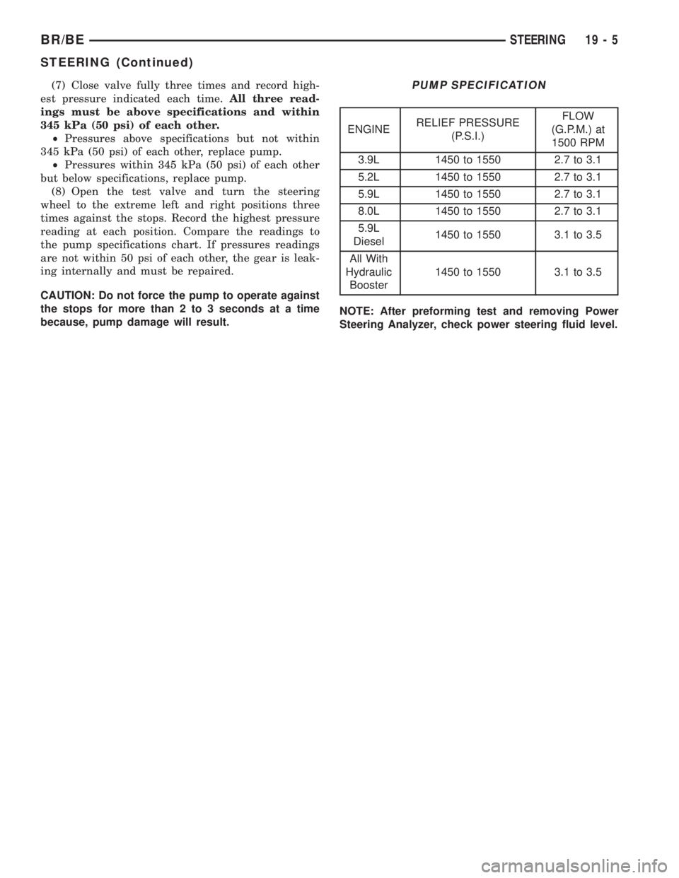
because, pump damage will result.PUMP SPECIFICATION
ENGINERELIEF PRESSURE
(P.S.I.)FLOW
(G.P.M.) at
1500 RPM
3.9L 1450 to 1550 2.7 to 3.1
5.2L 1450 to 1550 2.7 to 3.1
5.9L 1450 to 1550 2.7 to 3.1
8.0L 1450 to 1550 2.7 to 3.1
5.9L
Diesel1450 to 1550 3.1 to 3.5
All With
Hydraulic
Booster1450 to 1550 3.1 to 3.5
NOTE: After preforming test and removing Power
Steering Analyzer, check power steering fluid level.
BR/BESTEERING 19 - 5
STEERING (Continued)
Page 1599 of 2889
COLUMN
TABLE OF CONTENTS
page page
COLUMN
DESCRIPTION............................6
OPERATION.............................6
REMOVAL...............................7
INSTALLATION............................8
SPECIFICATIONS.........................9
KEY-IN IGNITION SWITCH
DESCRIPTION............................9
DIAGNOSIS AND TESTING.................10
IGNITION SWITCH AND KEY LOCK
CYLINDER............................10
LOCK CYLINDER HOUSING
REMOVAL..............................10
INSTALLATION...........................11IGNITION SWITCH
DESCRIPTION...........................11
OPERATION.............................11
DIAGNOSIS AND TESTING.................11
IGNITION SWITCH......................11
REMOVAL..............................12
INSTALLATION...........................12
GEAR SHIFT LEVER
REMOVAL..............................13
INSTALLATION...........................13
STEERING WHEEL
REMOVAL..............................13
INSTALLATION...........................13
COLUMN
DESCRIPTION
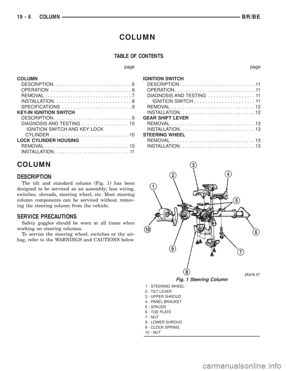
The tilt and standard column (Fig. 1) has been
designed to be serviced as an assembly; less wiring,
switches, shrouds, steering wheel, etc. Most steering
column components can be serviced without remov-
ing the steering column from the vehicle.
SERVICE PRECAUTIONS
Safety goggles should be worn at all times when
working on steering columns.
To service the steering wheel, switches or the air-
bag, refer to the WARNINGS and CAUTIONS below.
Fig. 1 Steering Column
1 - STEERING WHEEL
2 - TILT LEVER
3 - UPPER SHROUD
4 - PANEL BRACKET
5 - SPACER
6 - TOE PLATE
7 - NUT
8 - LOWER SHROUD
9 - CLOCK SPRING
10 - NUT
19 - 6 COLUMNBR/BE
Page 1600 of 2889
WARNING: THE AIRBAG SYSTEM IS A SENSITIVE,
COMPLEX ELECTRO-MECHANICAL UNIT. BEFORE
ATTEMPTING TO DIAGNOSE, REMOVE OR INSTALL
THE AIRBAG SYSTEM COMPONENTS YOU MUST
FIRST DISCONNECT AND ISOLATE THE BATTERY
NEGATIVE (GROUND) CABLE. THEN WAIT TWO
MINUTES FOR THE SYSTEM CAPACITOR TO DIS-
CHARGE. FAILURE TO DO SO COULD RESULT IN
ACCIDENTAL DEPLOYMENT OF THE AIRBAG AND
POSSIBLE PERSONAL INJURY. THE FASTENERS,
SCREWS, AND BOLTS, ORIGINALLY USED FOR
THE AIRBAG COMPONENTS, HAVE SPECIAL COAT-
INGS AND ARE SPECIFICALLY DESIGNED FOR THE
AIRBAG SYSTEM. THEY MUST NEVER BE
REPLACED WITH ANY SUBSTITUTES. ANYTIME A
NEW FASTENER IS NEEDED, REPLACE WITH THE
CORRECT FASTENERS PROVIDED IN THE SERVICE
PACKAGE OR FASTENERS LISTED IN THE PARTS
BOOKS.
CAUTION: Do not hammer on steering column shaft
or shift tube. This may cause the shaft/shift tube to
collapse or damage the bearing.
CAUTION: Do not attempt to remove the pivot pins
to disassemble the tilting mechanism. Do not
remove shaft lock plate, plate retainer, park lock
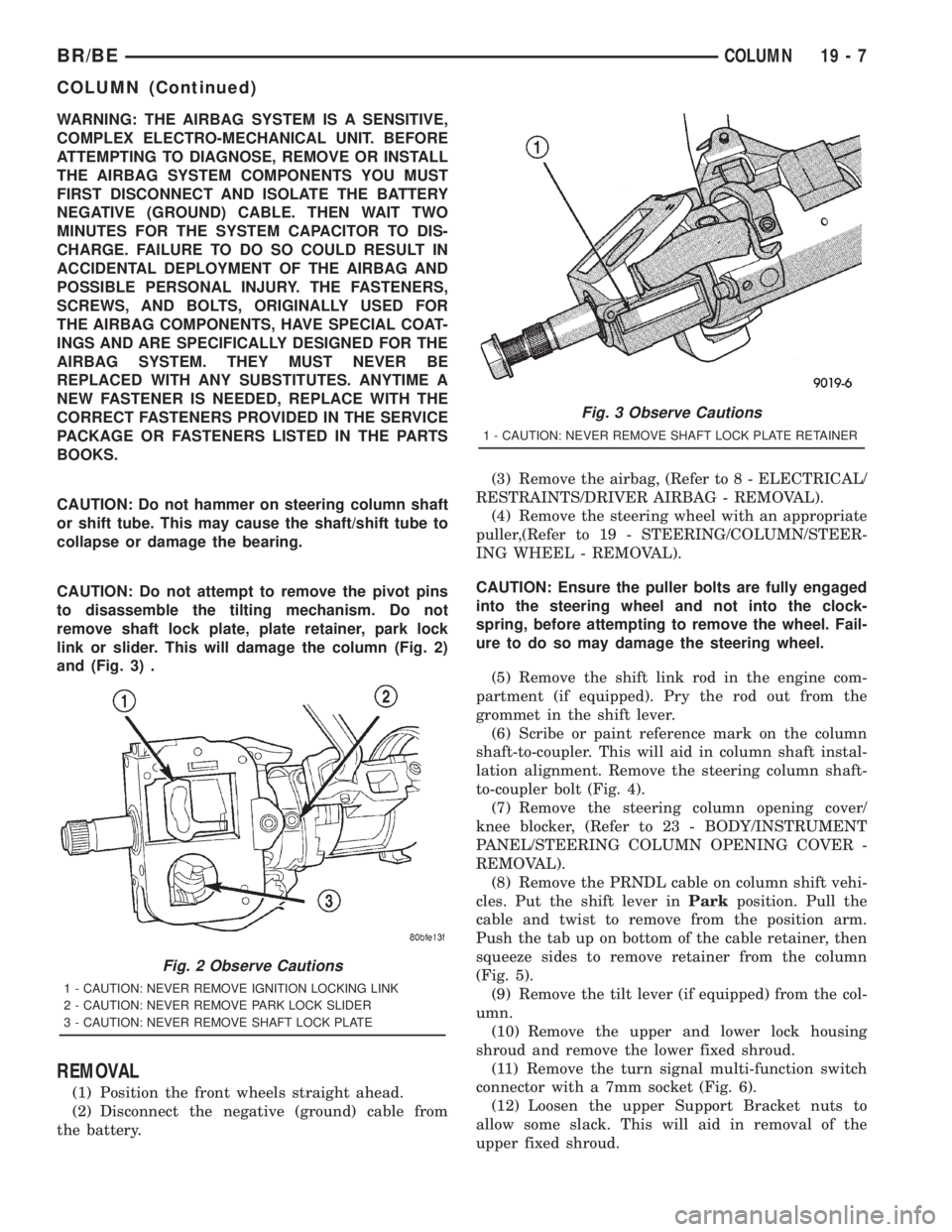
link or slider. This will damage the column (Fig. 2)
and (Fig. 3) .
REMOVAL
(1) Position the front wheels straight ahead.
(2) Disconnect the negative (ground) cable from
the battery.(3) Remove the airbag, (Refer to 8 - ELECTRICAL/
RESTRAINTS/DRIVER AIRBAG - REMOVAL).
(4) Remove the steering wheel with an appropriate
puller,(Refer to 19 - STEERING/COLUMN/STEER-
ING WHEEL - REMOVAL).
CAUTION: Ensure the puller bolts are fully engaged
into the steering wheel and not into the clock-
spring, before attempting to remove the wheel. Fail-
ure to do so may damage the steering wheel.
(5) Remove the shift link rod in the engine com-
partment (if equipped). Pry the rod out from the
grommet in the shift lever.
(6) Scribe or paint reference mark on the column
shaft-to-coupler. This will aid in column shaft instal-
lation alignment. Remove the steering column shaft-
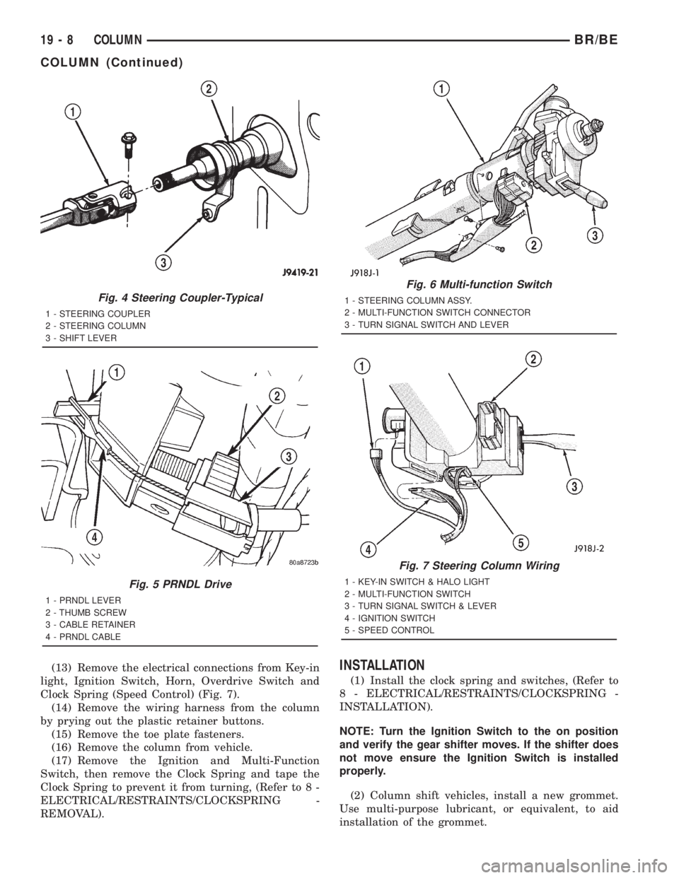
to-coupler bolt (Fig. 4).
(7) Remove the steering column opening cover/
knee blocker, (Refer to 23 - BODY/INSTRUMENT
PANEL/STEERING COLUMN OPENING COVER -
REMOVAL).
(8) Remove the PRNDL cable on column shift vehi-
cles. Put the shift lever inParkposition. Pull the
cable and twist to remove from the position arm.
Push the tab up on bottom of the cable retainer, then
squeeze sides to remove retainer from the column
(Fig. 5).
(9) Remove the tilt lever (if equipped) from the col-
umn.
(10) Remove the upper and lower lock housing
shroud and remove the lower fixed shroud.
(11) Remove the turn signal multi-function switch
connector with a 7mm socket (Fig. 6).
(12) Loosen the upper Support Bracket nuts to
allow some slack. This will aid in removal of the
upper fixed shroud.
Fig. 2 Observe Cautions
1 - CAUTION: NEVER REMOVE IGNITION LOCKING LINK
2 - CAUTION: NEVER REMOVE PARK LOCK SLIDER
3 - CAUTION: NEVER REMOVE SHAFT LOCK PLATE
Fig. 3 Observe Cautions
1 - CAUTION: NEVER REMOVE SHAFT LOCK PLATE RETAINER
BR/BECOLUMN 19 - 7
COLUMN (Continued)
Page 1601 of 2889
(13) Remove the electrical connections from Key-in
light, Ignition Switch, Horn, Overdrive Switch and
Clock Spring (Speed Control) (Fig. 7).
(14) Remove the wiring harness from the column
by prying out the plastic retainer buttons.
(15) Remove the toe plate fasteners.
(16) Remove the column from vehicle.
(17) Remove the Ignition and Multi-Function
Switch, then remove the Clock Spring and tape the
Clock Spring to prevent it from turning, (Refer to 8 -
ELECTRICAL/RESTRAINTS/CLOCKSPRING -
REMOVAL).INSTALLATION
(1) Install the clock spring and switches, (Refer to
8 - ELECTRICAL/RESTRAINTS/CLOCKSPRING -
INSTALLATION).
NOTE: Turn the Ignition Switch to the on position
and verify the gear shifter moves. If the shifter does
not move ensure the Ignition Switch is installed
properly.
(2) Column shift vehicles, install a new grommet.
Use multi-purpose lubricant, or equivalent, to aid
installation of the grommet.
Fig. 4 Steering Coupler-Typical
1 - STEERING COUPLER
2 - STEERING COLUMN
3 - SHIFT LEVER
Fig. 5 PRNDL Drive
1 - PRNDL LEVER
2 - THUMB SCREW
3 - CABLE RETAINER
4 - PRNDL CABLE
Fig. 6 Multi-function Switch
1 - STEERING COLUMN ASSY.
2 - MULTI-FUNCTION SWITCH CONNECTOR
3 - TURN SIGNAL SWITCH AND LEVER
Fig. 7 Steering Column Wiring
1 - KEY-IN SWITCH & HALO LIGHT
2 - MULTI-FUNCTION SWITCH
3 - TURN SIGNAL SWITCH & LEVER
4 - IGNITION SWITCH
5 - SPEED CONTROL
19 - 8 COLUMNBR/BE
COLUMN (Continued)
Page 1602 of 2889

NOTE: A new grommet should be used when ever
the rod is disconnected from the lever.
(3) Remove the shipping lock pin if necessary.
(4) Install the column through the floor pan.
(5) Position the column bracket breakaway cap-
sules on the mounting studs. Install, butloose
assemblethe two upper bracket nuts.
(6) With the front wheels in the straight-ahead
position. Align steering column shaft to the coupler.
Install anewpinch bolt and tighten to 49 N´m (36
ft. lbs.).
(7) Clip the wiring harness on the steering column.
Connect the multi- function switch wiring and
tighten with 7mm socket.
(8) Install the upper fixed shroud.
(9) Be sure both breakaway capsules are fully
seated in the slots in the column support bracket.
Pull the column rearward then tighten upper bracket
nuts to 12 N´m (105 in. lbs.).
(10) Tighten the toe plate to floor pan attaching
nuts to 22.5 N´m (200 in. lbs.).
(11) Install the wiring connections to the column.
Install the lower fixed shroud.(12) Column shift vehicles, install the PRNDL
driver cable. Place shifter in Park position. If indica-
tor needs adjusting, turn thumb screw on cable
retainer to adjust cable.
(13) Install the lock housing shrouds. Install the
tilt lever (if equipped).
(14) Install the knee blocker and steering column
opening cover, (Refer to 23 - BODY/INSTRUMENT
PANEL/STEERING COLUMN OPENING COVER -
INSTALLATION).
(15) Install steering wheel and tighten nut to 61
N´m (45 ft. lbs.), (Refer to 19 - STEERING/COL-
UMN/STEERING WHEEL - INSTALLATION).
(16) Install the airbag, (Refer to 8 - ELECTRICAL/
RESTRAINTS/DRIVER AIRBAG - INSTALLATION).
(17) Column shift vehicles, connect the shift link
rod to the transmission shift lever. Use multi-purpose
lubricant, or an equivalent product, to aid the instal-
lation.
(18) Install the battery ground (negative) cable.
(19) Verify operation of the automatic transmission
shift linkage and adjust as necessary, (Refer to 21 -
TRANSMISSION/TRANSAXLE/AUTOMATIC -
44RE/GEAR SHIFT CABLE - ADJUSTMENTS).
SPECIFICATIONS
TORQUE CHART
TORQUE SPECIFICATIONS
DESCRIPTION N´m Ft. Lbs. In. Lbs.
Steering Wheel
Nut61 45 Ð
Steering Coupler
Bolt49 36 Ð
Steering Column
Upper Bracket12 Ð 105
Steering Column
Toe Plate23 Ð 200
KEY-IN IGNITION SWITCH
DESCRIPTION
The key-in ignition switch is integral to the igni-
tion switch, which is mounted on the right side of the
steering column. It closes a path to ground for the
Central Timer Module (CTM) when the ignition key
is inserted in the ignition lock cylinder and thedriver door ajar switch is closed (driver door is open).
The key-in ignition switch opens the ground path
when the key is removed from the ignition lock cyl-
inder. The ground path is also opened when the
driver door ajar switch is open (driver door is closed).
The key-in ignition switch cannot be repaired and,
if faulty or damaged, the entire ignition switch must
be replaced,(Refer to 19 - STEERING/COLUMN/IG-
NITION SWITCH - REMOVAL).
BR/BECOLUMN 19 - 9
COLUMN (Continued)
Page 1603 of 2889
DIAGNOSIS AND TESTING - IGNITION SWITCH
AND KEY LOCK CYLINDER
ELECTRICAL DIAGNOSIS
For ignition switch electrical schematics, refer to
Ignition Switch in the appropriate section of Electri-
cal Wiring Diagrams.
MECHANICAL DIAGNOSIS (KEY DIFFICULT TO
ROTATE)
Vehicles equipped with an automatic trans-
mission and a floor mounted shifter:a cable is
used to connect the interlock device in the steering
column assembly, to the transmission floor shift
lever. This interlock device is used to lock the trans-
mission shifter in the PARK position when the key
lock cylinder is rotated to the LOCKED or ACCES-
SORY position. The interlock device within the steer-
ing column is not serviceable. If repair is necessary,
the steering column assembly must be replaced.
(Refer to 19 - STEERING/COLUMN - REMOVAL).
If the ignition key is difficult to rotate to or from
the LOCK or ACCESSORY position, it may not be
the fault of the key cylinder or the steering column
components. The brake transmission shift interlock
cable may be out of adjustment. Refer to Brake
Transmission Shift Interlock Cable Adjustment in
Transmissions for adjustment procedures.
Vehicles equipped with an automatic trans-
mission and a steering column mounted shifter:
an interlock device is located within the steering col-
umn. This interlock device is used to lock the trans-
mission shifter in the PARK position when the key
lock cylinder is in the LOCKED or ACCESSORY
position. If it is difficult to rotate the key to or from
the LOCK or ACCESSORY position, the interlock
device within the steering column may be defective.
This device is not serviceable. If repair is necessary,
the steering column assembly must be replaced.
(Refer to 19 - STEERING/COLUMN - REMOVAL).
Vehicles equipped with a manual transmis-
sion and a floor mounted shifter:on certain mod-
els, a lever is located on the steering column behind
the ignition key lock cylinder. The lever must be
manually operated to allow rotation of the ignition
key lock cylinder to the LOCK or ACCESSORY posi-
tion. If it is difficult to rotate the key to the LOCK or
ACCESSORY position, the lever mechanism may be
defective. This mechanism is not serviceable. If
repair is necessary, the steering column assembly
must be replaced. (Refer to 19 - STEERING/COL-
UMN - REMOVAL).
On other models, the ignition key cylinder must be
depressed to allow it to be rotated into the LOCK or
ACCESSORY position. If it is difficult to rotate the
key to the LOCK or ACCESSORY position, the lockmechanism within the steering column may be defec-
tive. This mechanism is not serviceable. If repair is
necessary, the steering column assembly must be
replaced. (Refer to 19 - STEERING/COLUMN -
REMOVAL).
LOCK CYLINDER HOUSING
REMOVAL
The ignition key must be in the key cylinder for
cylinder removal.
(1) Disconnect negative cable from battery.
(2) If equipped with tilt column, remove tilt lever
by turning it counterclockwise.
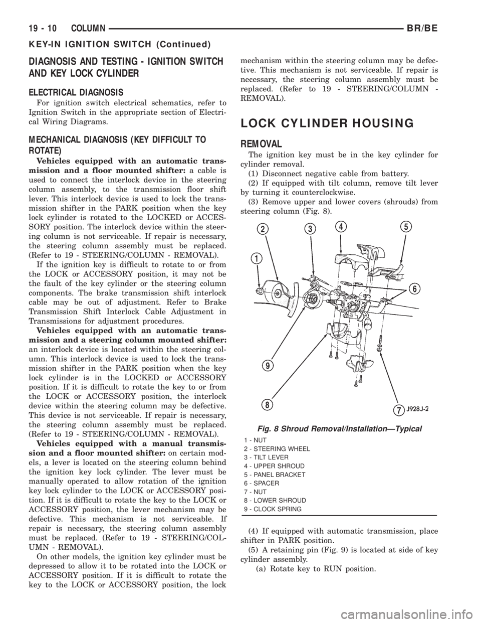
(3) Remove upper and lower covers (shrouds) from
steering column (Fig. 8).
(4) If equipped with automatic transmission, place
shifter in PARK position.
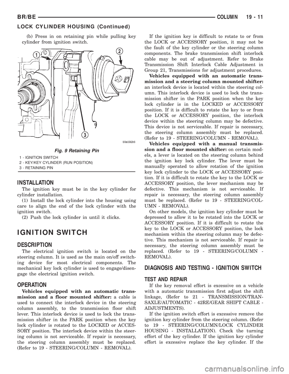
(5) A retaining pin (Fig. 9) is located at side of key
cylinder assembly.
(a) Rotate key to RUN position.
Fig. 8 Shroud Removal/InstallationÐTypical
1 - NUT
2 - STEERING WHEEL
3 - TILT LEVER
4 - UPPER SHROUD
5 - PANEL BRACKET
6 - SPACER
7 - NUT
8 - LOWER SHROUD
9 - CLOCK SPRING
19 - 10 COLUMNBR/BE
KEY-IN IGNITION SWITCH (Continued)
Page 1604 of 2889
(b) Press in on retaining pin while pulling key
cylinder from ignition switch.
INSTALLATION
The ignition key must be in the key cylinder for
cylinder installation.
(1) Install the lock cylinder into the housing using
care to align the end of the lock cylinder with the
ignition switch.
(2) Push the lock cylinder in until it clicks.
IGNITION SWITCH
DESCRIPTION
The electrical ignition switch is located on the
steering column. It is used as the main on/off switch-
ing device for most electrical components. The
mechanical key lock cylinder is used to engage/disen-
gage the electrical ignition switch.
OPERATION
Vehicles equipped with an automatic trans-
mission and a floor mounted shifter:a cable is
used to connect the interlock device in the steering
column assembly, to the transmission floor shift
lever. This interlock device is used to lock the trans-
mission shifter in the PARK position when the key
lock cylinder is rotated to the LOCKED or ACCES-
SORY position. The interlock device within the steer-
ing column is not serviceable. If repair is necessary,
the steering column assembly must be replaced.
(Refer to 19 - STEERING/COLUMN - REMOVAL).If the ignition key is difficult to rotate to or from
the LOCK or ACCESSORY position, it may not be
the fault of the key cylinder or the steering column
components. The brake transmission shift interlock
cable may be out of adjustment. Refer to Brake
Transmission Shift Interlock Cable Adjustment in
Group 21, Transmissions for adjustment procedures.
Vehicles equipped with an automatic trans-
mission and a steering column mounted shifter:
an interlock device is located within the steering col-
umn. This interlock device is used to lock the trans-
mission shifter in the PARK position when the key
lock cylinder is in the LOCKED or ACCESSORY
position. If it is difficult to rotate the key to or from
the LOCK or ACCESSORY position, the interlock
device within the steering column may be defective.
This device is not serviceable. If repair is necessary,
the steering column assembly must be replaced.
(Refer to 19 - STEERING/COLUMN - REMOVAL).
Vehicles equipped with a manual transmis-
sion and a floor mounted shifter:on certain mod-
els, a lever is located on the steering column behind
the ignition key lock cylinder. The lever must be
manually operated to allow rotation of the ignition
key lock cylinder to the LOCK or ACCESSORY posi-
tion. If it is difficult to rotate the key to the LOCK or
ACCESSORY position, the lever mechanism may be
defective. This mechanism is not serviceable. If
repair is necessary, the steering column assembly
must be replaced. (Refer to 19 - STEERING/COL-
UMN - REMOVAL).
On other models, the ignition key cylinder must be
depressed to allow it to be rotated into the LOCK or
ACCESSORY position. If it is difficult to rotate the
key to the LOCK or ACCESSORY position, the lock
mechanism within the steering column may be defec-
tive. This mechanism is not serviceable. If repair is
necessary, the steering column assembly must be
replaced. (Refer to 19 - STEERING/COLUMN -
REMOVAL).
DIAGNOSIS AND TESTING - IGNITION SWITCH
TEST AND REPAIR
If the key removal effort is excessive on a vehicle
with a automatic transmission first adjust the shift
linkage, (Refer to 21 - TRANSMISSION/TRAN-
SAXLE/AUTOMATIC - 42RE/GEAR SHIFT CABLE -
ADJUSTMENTS).
If the ignition switch effort is excessive remove the
ignition key cylinder from the steering column. (Refer
to 19 - STEERING/COLUMN/LOCK CYLINDER
HOUSING - INSTALLATION). Check the turning
effort of the key cylinder. If the ignition key cylinder
effort is excessive replace the key cylinder. If the
Fig. 9 Retaining Pin
1 - IGNITION SWITCH
2 - KEY/KEY CYLINDER (RUN POSITION)
3 - RETAINING PIN
BR/BECOLUMN 19 - 11
LOCK CYLINDER HOUSING (Continued)
Page 1605 of 2889
ignition key cylinder operates properly look for the
following conditions.
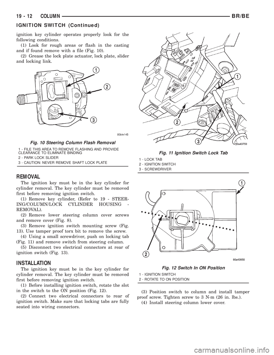
(1) Look for rough areas or flash in the casting
and if found remove with a file (Fig. 10).
(2) Grease the lock plate actuator, lock plate, slider
and locking link.
REMOVAL
The ignition key must be in the key cylinder for
cylinder removal. The key cylinder must be removed
first before removing ignition switch.
(1) Remove key cylinder, (Refer to 19 - STEER-
ING/COLUMN/LOCK CYLINDER HOUSING -
REMOVAL).
(2) Remove lower steering column cover screws
and remove cover (Fig. 8).
(3) Remove ignition switch mounting screw (Fig.
13). Use tamper proof torx bit to remove the screw.
(4) Using a small screwdriver, push on locking tab
(Fig. 11) and remove switch from steering column.
(5) Disconnect two electrical connectors at rear of
ignition switch (Fig. 13).
INSTALLATION
The ignition key must be in the key cylinder for
cylinder removal. The key cylinder must be removed
first before removing ignition switch.
(1) Before installing ignition switch, rotate the slot
in the switch to the ON position (Fig. 12).
(2) Connect two electrical connectors to rear of
ignition switch. Make sure that locking tabs are fully
seated into wiring connectors.(3) Position switch to column and install tamper
proof screw. Tighten screw to 3 N´m (26 in. lbs.).
(4) Install steering column lower cover.
Fig. 10 Steering Column Flash Removal
1 - FILE THIS AREA TO REMOVE FLASHING AND PROVIDE
CLEARANCE TO ELIMINATE BINDING
2 - PARK LOCK SLIDER
3 - CAUTION: NEVER REMOVE SHAFT LOCK PLATEFig. 11 Ignition Switch Lock Tab
1 - LOCK TAB
2 - IGNITION SWITCH
3 - SCREWDRIVER
Fig. 12 Switch In ON Position
1 - IGNITION SWITCH
2 - ROTATE TO ON POSITION
19 - 12 COLUMNBR/BE
IGNITION SWITCH (Continued)