2001 DODGE RAM steering
[x] Cancel search: steeringPage 1096 of 2889
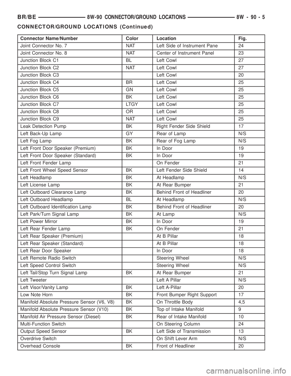
Connector Name/Number Color Location Fig.
Joint Connector No. 7 NAT Left Side of Instrument Pane 24
Joint Connector No. 8 NAT Center of Instrument Panel 23
Junction Block C1 BL Left Cowl 27
Junction Block C2 NAT Left Cowl 27
Junction Block C3 Left Cowl 20
Junction Block C4 BR Left Cowl 25
Junction Block C5 GN Left Cowl 25
Junction Block C6 BK Left Cowl 25
Junction Block C7 LTGY Left Cowl 25
Junction Block C8 OR Left Cowl 25
Junction Block C9 NAT Left Cowl 25
Leak Detection Pump BK Right Fender Side Shield 17
Left Back-Up Lamp GY Rear of Lamp N/S
Left Fog Lamp BK Rear of Fog Lamp N/S
Left Front Door Speaker (Premium) BK In Door 19
Left Front Door Speaker (Standard) BK In Door 19
Left Front Fender Lamp On Fender 21
Left Front Wheel Speed Sensor BK Left Fender Side Shield 14
Left Headlamp BK At Headlamp N/S
Left License Lamp BK At Rear Bumper 21
Left Outboard Clearance Lamp BK Behind Front of Headliner 20
Left Outboard Headlamp BL At Headlamp N/S
Left Outboard Identification Lamp BK Behind Front of Headliner 20
Left Park/Turn Signal Lamp BK At Lamp N/S
Left Power Mirror BK In Door 19
Left Rear Fender Lamp BK On Fender 21
Left Rear Speaker (Premium) At B Pillar 18
Left Rear Speaker (Standard) At B Pillar 18
Left Rear Door Speaker In Door 18
Left Remote Radio Switch Steering Wheel N/S
Left Speed Control Switch Steering Wheel N/S
Left Tail/Stop Turn Signal Lamp BK At Rear Bumper 21
Left Tweeter Left A Pillar N/S
Left Visor/Vanity Lamp BK Left A-Pillar 20
Low Note Horn BK Front Bumper Right Support 17
Manifold Absolute Pressure Sensor (V6, V8) BK On Throttle Body 4,5
Manifold Absolute Pressure Sensor (V10) BK Top of Intake Manifold 9
Manifold Air Pressure Sensor (Diesel) BK Rear of Intake Manifold 10
Multi-Function Switch On Steering Column 24
Output Speed Sensor BK Left Side of Transmission 13
Overdrive Switch On Shift Lever Arm N/S
Overhead Console BK Front of Headliner 20
BR/BE8W-90 CONNECTOR/GROUND LOCATIONS 8W - 90 - 5
CONNECTOR/GROUND LOCATIONS (Continued)
Page 1098 of 2889
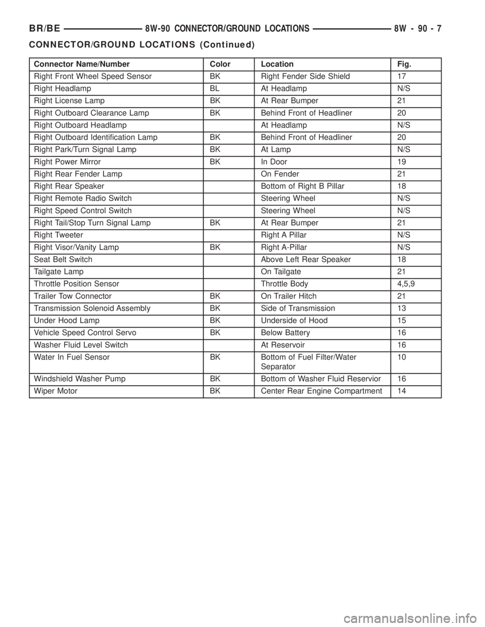
Connector Name/Number Color Location Fig.
Right Front Wheel Speed Sensor BK Right Fender Side Shield 17
Right Headlamp BL At Headlamp N/S
Right License Lamp BK At Rear Bumper 21
Right Outboard Clearance Lamp BK Behind Front of Headliner 20
Right Outboard Headlamp At Headlamp N/S
Right Outboard Identification Lamp BK Behind Front of Headliner 20
Right Park/Turn Signal Lamp BK At Lamp N/S
Right Power Mirror BK In Door 19
Right Rear Fender Lamp On Fender 21
Right Rear Speaker Bottom of Right B Pillar 18
Right Remote Radio Switch Steering Wheel N/S
Right Speed Control Switch Steering Wheel N/S
Right Tail/Stop Turn Signal Lamp BK At Rear Bumper 21
Right Tweeter Right A Pillar N/S
Right Visor/Vanity Lamp BK Right A-Pillar N/S
Seat Belt Switch Above Left Rear Speaker 18
Tailgate Lamp On Tailgate 21
Throttle Position Sensor Throttle Body 4,5,9
Trailer Tow Connector BK On Trailer Hitch 21
Transmission Solenoid Assembly BK Side of Transmission 13
Under Hood Lamp BK Underside of Hood 15
Vehicle Speed Control Servo BK Below Battery 16
Washer Fluid Level Switch At Reservoir 16
Water In Fuel Sensor BK Bottom of Fuel Filter/Water
Separator10
Windshield Washer Pump BK Bottom of Washer Fluid Reservior 16
Wiper Motor BK Center Rear Engine Compartment 14
BR/BE8W-90 CONNECTOR/GROUND LOCATIONS 8W - 90 - 7
CONNECTOR/GROUND LOCATIONS (Continued)
Page 1119 of 2889
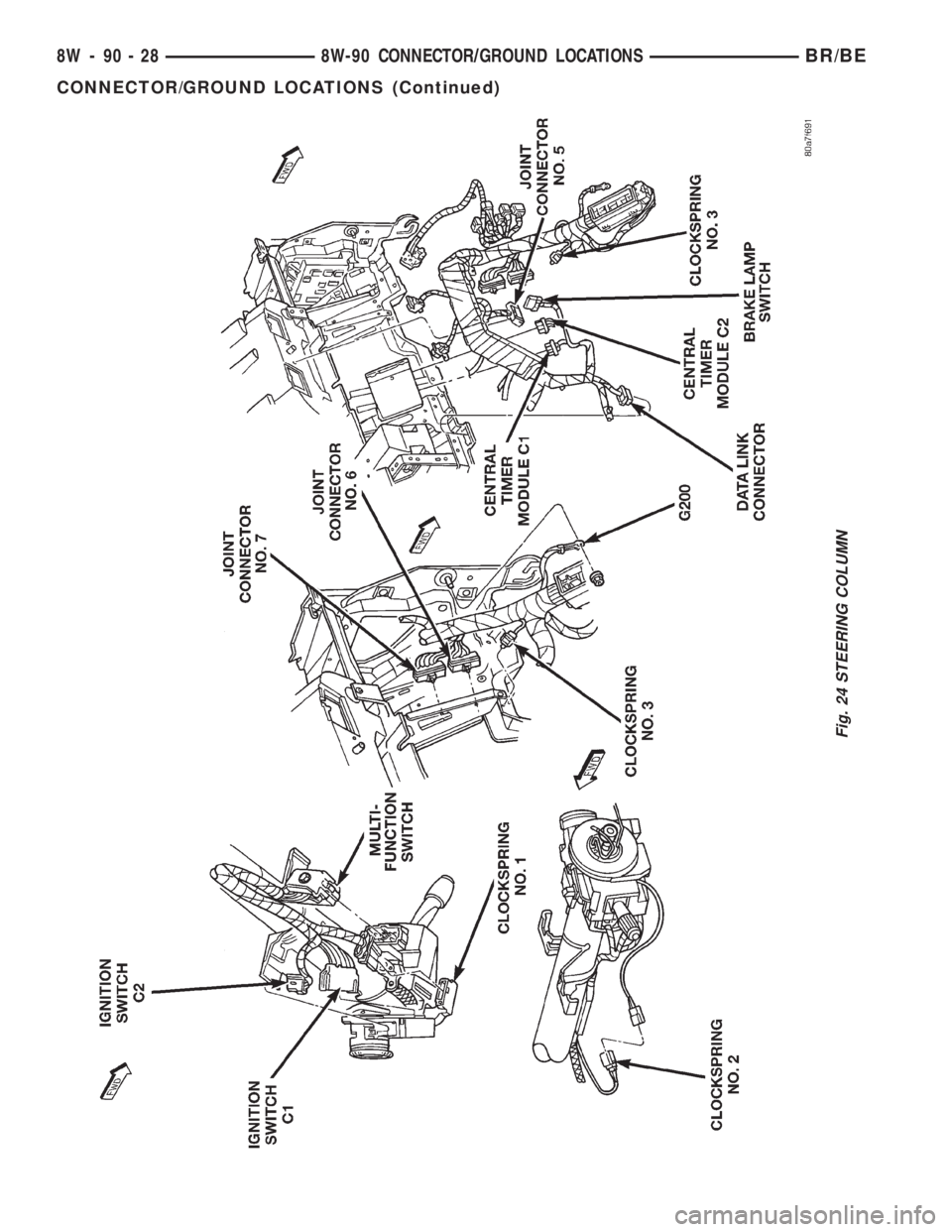
Fig. 24 STEERING COLUMN
8W - 90 - 28 8W-90 CONNECTOR/GROUND LOCATIONSBR/BE
CONNECTOR/GROUND LOCATIONS (Continued)
Page 1125 of 2889
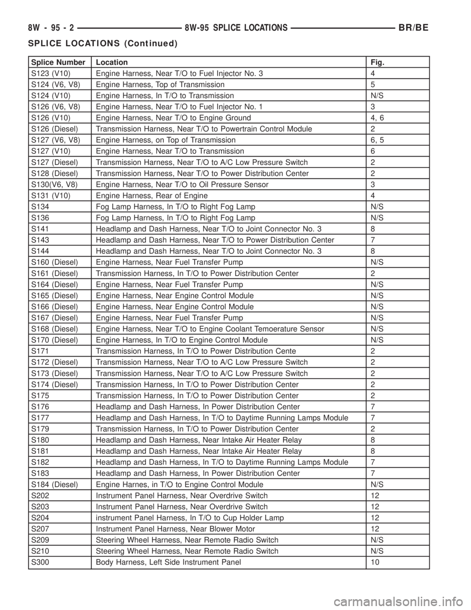
Splice Number Location Fig.
S123 (V10) Engine Harness, Near T/O to Fuel Injector No. 3 4
S124 (V6, V8) Engine Harness, Top of Transmission 5
S124 (V10) Engine Harness, In T/O to Transmission N/S
S126 (V6, V8) Engine Harness, Near T/O to Fuel Injector No. 1 3
S126 (V10) Engine Harness, Near T/O to Engine Ground 4, 6
S126 (Diesel) Transmission Harness, Near T/O to Powertrain Control Module 2
S127 (V6, V8) Engine Harness, on Top of Transmission 6, 5
S127 (V10) Engine Harness, Near T/O to Transmission 6
S127 (Diesel) Transmission Harness, Near T/O to A/C Low Pressure Switch 2
S128 (Diesel) Transmission Harness, Near T/O to Power Distribution Center 2
S130(V6, V8) Engine Harness, Near T/O to Oil Pressure Sensor 3
S131 (V10) Engine Harness, Rear of Engine 4
S134 Fog Lamp Harness, In T/O to Right Fog Lamp N/S
S136 Fog Lamp Harness, In T/O to Right Fog Lamp N/S
S141 Headlamp and Dash Harness, Near T/O to Joint Connector No. 3 8
S143 Headlamp and Dash Harness, Near T/O to Power Distribution Center 7
S144 Headlamp and Dash Harness, Near T/O to Joint Connector No. 3 8
S160 (Diesel) Engine Harness, Near Fuel Transfer Pump N/S
S161 (Diesel) Transmission Harness, In T/O to Power Distribution Center 2
S164 (Diesel) Engine Harness, Near Fuel Transfer Pump N/S
S165 (Diesel) Engine Harness, Near Engine Control Module N/S
S166 (Diesel) Engine Harness, Near Engine Control Module N/S
S167 (Diesel) Engine Harness, Near Fuel Transfer Pump N/S
S168 (Diesel) Engine Harness, Near T/O to Engine Coolant Temoerature Sensor N/S
S170 (Diesel) Engine Harness, In T/O to Engine Control Module N/S
S171 Transmission Harness, In T/O to Power Distribution Cente 2
S172 (Diesel) Transmission Harness, Near T/O to A/C Low Pressure Switch 2
S173 (Diesel) Transmission Harness, Near T/O to A/C Low Pressure Switch 2
S174 (Diesel) Transmission Harness, In T/O to Power Distribution Center 2
S175 Transmission Harness, In T/O to Power Distribution Center 2
S176 Headlamp and Dash Harness, In Power Distribution Center 7
S177 Headlamp and Dash Harness, In T/O to Daytime Running Lamps Module 7
S179 Transmission Harness, In T/O to Power Distribution Center 2
S180 Headlamp and Dash Harness, Near Intake Air Heater Relay 8
S181 Headlamp and Dash Harness, Near Intake Air Heater Relay 8
S182 Headlamp and Dash Harness, In T/O to Daytime Running Lamps Module 7
S183 Headlamp and Dash Harness, In Power Distribution Center 7
S184 (Diesel) Engine Harnes, in T/O to Engine Control Module N/S
S202 Instrument Panel Harness, Near Overdrive Switch 12
S203 Instrument Panel Harness, Near Overdrive Switch 12
S204 instrument Panel Harness, In T/O to Cup Holder Lamp 12
S207 Instrument Panel Harness, Near Blower Motor 12
S209 Steering Wheel Harness, Near Remote Radio Switch N/S
S210 Steering Wheel Harness, Near Remote Radio Switch N/S
S300 Body Harness, Left Side Instrument Panel 10
8W - 95 - 2 8W-95 SPLICE LOCATIONSBR/BE
SPLICE LOCATIONS (Continued)
Page 1137 of 2889
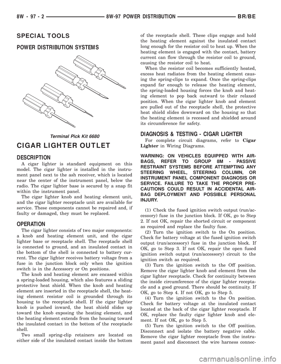
SPECIAL TOOLS
POWER DISTRIBUTION SYSTEMS
CIGAR LIGHTER OUTLET
DESCRIPTION
A cigar lighter is standard equipment on this
model. The cigar lighter is installed in the instru-
ment panel next to the ash receiver, which is located
near the center of the instrument panel, below the
radio. The cigar lighter base is secured by a snap fit
within the instrument panel.
The cigar lighter knob and heating element unit,
and the cigar lighter receptacle unit are available for
service. These components cannot be repaired and, if
faulty or damaged, they must be replaced.
OPERATION
The cigar lighter consists of two major components:
a knob and heating element unit, and the cigar
lighter base or receptacle shell. The receptacle shell
is connected to ground, and an insulated contact in
the bottom of the shell is connected to battery cur-
rent. The cigar lighter receives battery voltage from a
fuse in the junction block only when the ignition
switch is in the Accessory or On positions.
The knob and heating element are encased within
a spring-loaded housing, which also features a sliding
protective heat shield. When the knob and heating
element are inserted in the receptacle shell, the heat-
ing element resistor coil is grounded through its
housing to the receptacle shell. If the cigar lighter
knob is pushed inward, the heat shield slides up
toward the knob exposing the heating element, and
the heating element extends from the housing toward
the insulated contact in the bottom of the receptacle
shell.
Two small spring-clip retainers are located on
either side of the insulated contact inside the bottomof the receptacle shell. These clips engage and hold
the heating element against the insulated contact
long enough for the resistor coil to heat up. When the
heating element is engaged with the contact, battery
current can flow through the resistor coil to ground,
causing the resistor coil to heat.
When the resistor coil becomes sufficiently heated,
excess heat radiates from the heating element caus-
ing the spring-clips to expand. Once the spring-clips
expand far enough to release the heating element,
the spring-loaded housing forces the knob and heat-
ing element to pop back outward to their relaxed
position. When the cigar lighter knob and element
are pulled out of the receptacle shell, the protective
heat shield slides downward on the housing so that
the heating element is recessed and shielded around
its circumference for safety.
DIAGNOSIS & TESTING - CIGAR LIGHTER
For complete circuit diagrams, refer toCigar
Lighterin Wiring Diagrams.
WARNING: ON VEHICLES EQUIPPED WITH AIR-
BAGS, REFER TO GROUP 8M - PASSIVE
RESTRAINT SYSTEMS BEFORE ATTEMPTING ANY
STEERING WHEEL, STEERING COLUMN, OR
INSTRUMENT PANEL COMPONENT DIAGNOSIS OR
SERVICE. FAILURE TO TAKE THE PROPER PRE-
CAUTIONS COULD RESULT IN ACCIDENTAL AIR-
BAG DEPLOYMENT AND POSSIBLE PERSONAL
INJURY.
(1) Check the fused ignition switch output (run/ac-
cessory) fuse in the junction block. If OK, go to Step
2. If not OK, repair the shorted circuit or component
as required and replace the faulty fuse.
(2) Turn the ignition switch to the On position.
Check for battery voltage at the fused ignition switch
output (run/accessory) fuse in the junction block. If
OK, go to Step 3. If not OK, repair the open fused
ignition switch output (run/accessory) circuit to the
ignition switch as required.
(3) Turn the ignition switch to the Off position.
Remove the cigar lighter knob and element from the
cigar lighter receptacle. Check for continuity between
the inside circumference of the cigar lighter recepta-
cle and a good ground. There should be continuity. If
OK, go to Step 4. If not OK, go to Step 5.
(4) Turn the ignition switch to the On position.
Check for battery voltage at the insulated contact
located at the back of the cigar lighter receptacle. If
OK, replace the faulty cigar lighter knob and ele-
ment. If not OK, go to Step 5.
(5) Turn the ignition switch to the Off position.
Disconnect and isolate the battery negative cable.
Remove the cigar lighter receptacle from the instru-
ment panel and disconnect the wire harness connec-Terminal Pick Kit 6680
8W - 97 - 2 8W-97 POWER DISTRIBUTIONBR/BE
Page 1142 of 2889
(2) Roll down the instrument panel from the dash
panel, but do not remove it from the vehicle. Refer to
Instrument Panel Assemblyin the index of this
service manual for the instrument panel assembly
removal procedures.
(3) Reach through the outboard side of the instru-
ment panel steering column opening to access and
disconnect all of the wire harness connectors from
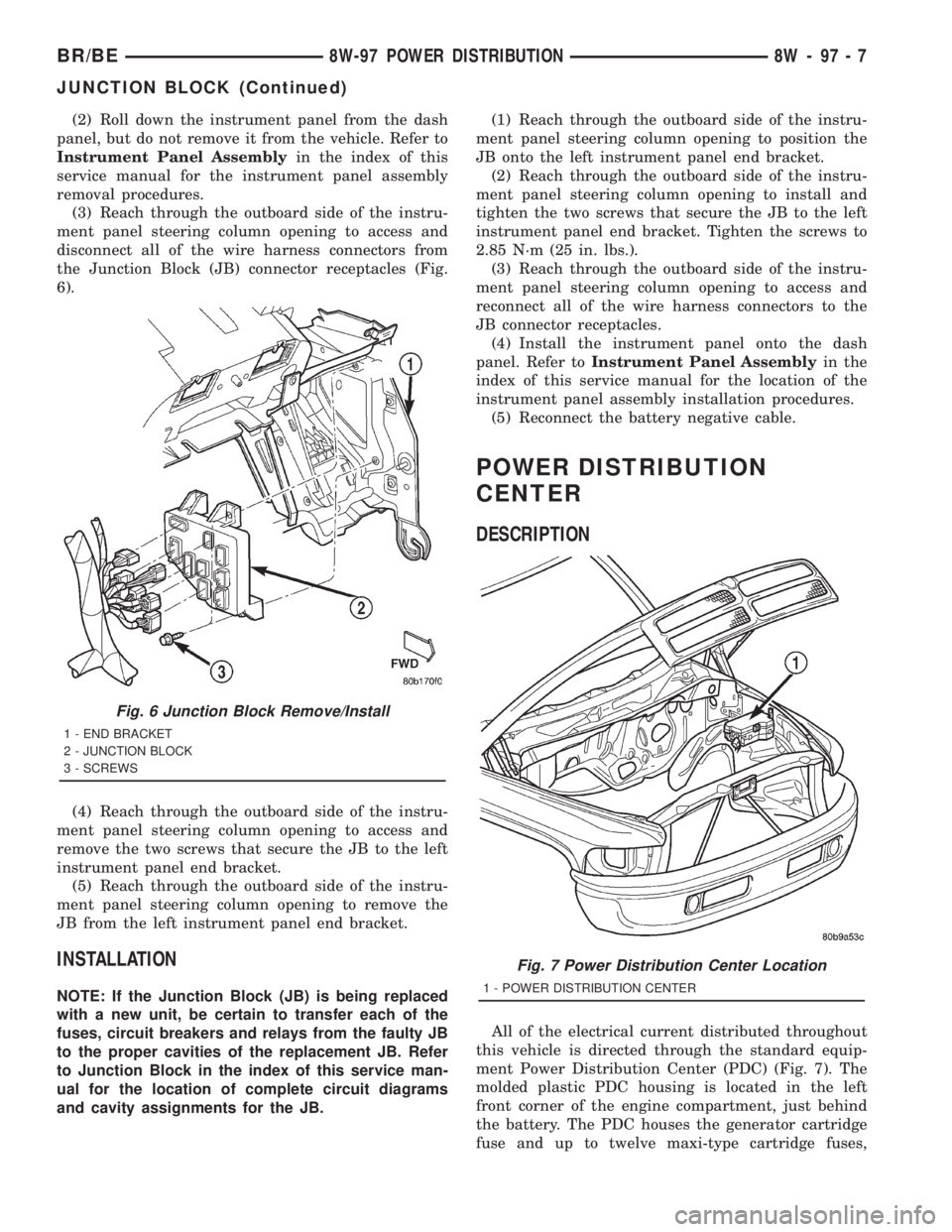
the Junction Block (JB) connector receptacles (Fig.
6).
(4) Reach through the outboard side of the instru-
ment panel steering column opening to access and
remove the two screws that secure the JB to the left
instrument panel end bracket.
(5) Reach through the outboard side of the instru-
ment panel steering column opening to remove the
JB from the left instrument panel end bracket.
INSTALLATION
NOTE: If the Junction Block (JB) is being replaced
with a new unit, be certain to transfer each of the
fuses, circuit breakers and relays from the faulty JB
to the proper cavities of the replacement JB. Refer
to Junction Block in the index of this service man-
ual for the location of complete circuit diagrams
and cavity assignments for the JB.(1) Reach through the outboard side of the instru-
ment panel steering column opening to position the
JB onto the left instrument panel end bracket.
(2) Reach through the outboard side of the instru-
ment panel steering column opening to install and
tighten the two screws that secure the JB to the left
instrument panel end bracket. Tighten the screws to
2.85 N´m (25 in. lbs.).
(3) Reach through the outboard side of the instru-
ment panel steering column opening to access and
reconnect all of the wire harness connectors to the
JB connector receptacles.
(4) Install the instrument panel onto the dash
panel. Refer toInstrument Panel Assemblyin the
index of this service manual for the location of the
instrument panel assembly installation procedures.
(5) Reconnect the battery negative cable.
POWER DISTRIBUTION
CENTER
DESCRIPTION
All of the electrical current distributed throughout
this vehicle is directed through the standard equip-
ment Power Distribution Center (PDC) (Fig. 7). The
molded plastic PDC housing is located in the left
front corner of the engine compartment, just behind
the battery. The PDC houses the generator cartridge
fuse and up to twelve maxi-type cartridge fuses,
Fig. 6 Junction Block Remove/Install
1 - END BRACKET
2 - JUNCTION BLOCK
3 - SCREWS
Fig. 7 Power Distribution Center Location
1 - POWER DISTRIBUTION CENTER
BR/BE8W-97 POWER DISTRIBUTION 8W - 97 - 7
JUNCTION BLOCK (Continued)
Page 1145 of 2889
the instrument panel, below the radio. The power
outlet base is secured by a snap fit within the instru-
ment panel. A plastic protective cap snaps into the
power outlet base when the power outlet is not being
used, and hangs from the power outlet base mount
by an integral bail strap while the power outlet is in
use.
The power outlet receptacle unit and the accessory
power outlet protective cap are available for service.
The power outlet receptacle cannot be repaired and,
if faulty or damaged, it must be replaced.
OPERATION
The power outlet base or receptacle shell is con-
nected to ground, and an insulated contact in the
bottom of the shell is connected to battery current.
The power outlet receives battery voltage from a fuse
in the Power Distribution Center (PDC) at all times.
While the power outlet is very similar to a cigar
lighter base unit, it does not include the two small
spring-clip retainers inside the bottom of the recepta-
cle shell that are used to secure the cigar lighter
heating element to the insulated contact.
DIAGNOSIS & TESTING - POWER OUTLET
For complete circuit diagrams, refer toPower
Outletin Wiring Diagrams.
WARNING: ON VEHICLES EQUIPPED WITH AIR-
BAGS, REFER TO GROUP 8M - PASSIVE
RESTRAINT SYSTEMS BEFORE ATTEMPTING ANY
STEERING WHEEL, STEERING COLUMN, OR
INSTRUMENT PANEL COMPONENT DIAGNOSIS OR
SERVICE. FAILURE TO TAKE THE PROPER PRE-
CAUTIONS COULD RESULT IN ACCIDENTAL AIR-
BAG DEPLOYMENT AND POSSIBLE PERSONAL
INJURY.
(1) Check the fused B(+) fuse in the Power Distri-
bution Center (PDC). If OK, go to Step 2. If not OK,
repair the shorted circuit or component as required
and replace the faulty fuse.
(2) Check for battery voltage at the fused B(+) fuse
in the PDC. If OK, go to Step 3. If not OK, repair the
open fused B(+) circuit to the battery as required.
(3) Remove the plastic protective cap from the
power outlet receptacle. Check for continuity between
the inside circumference of the power outlet recepta-
cle and a good ground. There should be continuity. If
OK, go to Step 4. If not OK, go to Step 5.
(4) Check for battery voltage at the insulated con-
tact located at the back of the power outlet recepta-
cle. If not OK, go to Step 5.
(5) Disconnect and isolate the battery negative
cable. Remove the power outlet receptacle from the
instrument panel. Disconnect the wire harness con-
nector from the power outlet receptacle. Check forcontinuity between the ground circuit cavity of the
power outlet wire harness connector and a good
ground. There should be continuity. If OK, go to Step
6. If not OK, repair the open ground circuit to ground
as required.
(6) Connect the battery negative cable. Check for
battery voltage at the fused B(+) circuit cavity of the
power outlet wire harness connector. If OK, replace
the faulty power outlet receptacle. If not OK, repair
the open fused B(+) circuit to the PDC fuse as
required.
REMOVAL
(1) Disconnect and isolate the battery negative
cable.
(2) Pull the cigar lighter knob and element out of
the cigar lighter receptacle base, or unsnap the pro-
tective cap from the power outlet receptacle base
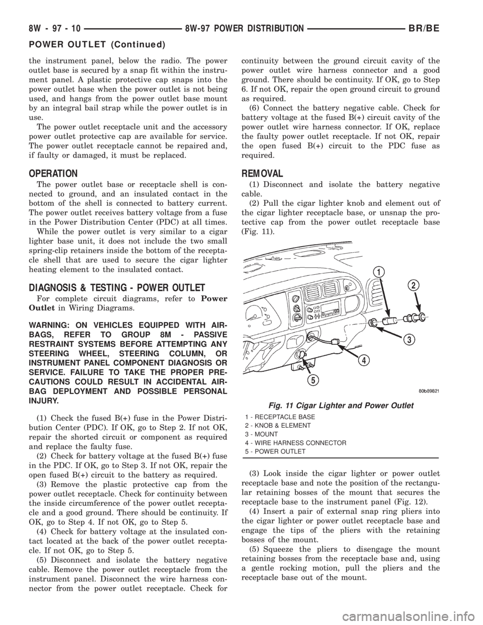
(Fig. 11).
(3) Look inside the cigar lighter or power outlet
receptacle base and note the position of the rectangu-
lar retaining bosses of the mount that secures the
receptacle base to the instrument panel (Fig. 12).
(4) Insert a pair of external snap ring pliers into
the cigar lighter or power outlet receptacle base and
engage the tips of the pliers with the retaining
bosses of the mount.
(5) Squeeze the pliers to disengage the mount
retaining bosses from the receptacle base and, using
a gentle rocking motion, pull the pliers and the
receptacle base out of the mount.
Fig. 11 Cigar Lighter and Power Outlet
1 - RECEPTACLE BASE
2 - KNOB & ELEMENT
3 - MOUNT
4 - WIRE HARNESS CONNECTOR
5 - POWER OUTLET
8W - 97 - 10 8W-97 POWER DISTRIBUTIONBR/BE
POWER OUTLET (Continued)
Page 1159 of 2889
material is for use between two machined surfaces.
Do not use on flexible metal flanges.
MOPARtGASKET SEALANT
MopartGasket Sealant is a slow drying, perma-
nently soft sealer. This material is recommended for
sealing threaded fittings and gaskets against leakage
of oil and coolant. Can be used on threaded and
machined parts under all temperatures. This mate-
rial is used on engines with multi-layer steel (MLS)
cylinder head gaskets. This material also will pre-
vent corrosion. MopartGasket Sealant is available in
a 13 oz. aerosol can or 4oz./16 oz. can w/applicator.
FORM-IN-PLACE GASKET AND SEALER
APPLICATION
Assembling parts using a form-in-place gasket
requires care but it's easier then using precut gas-
kets.
MopartGasket Maker material should be applied
sparingly 1 mm (0.040 in.) diameter or less of sealant
to one gasket surface. Be certain the material sur-
rounds each mounting hole. Excess material can eas-
ily be wiped off. Components should be torqued in
place within 15 minutes. The use of a locating dowel
is recommended during assembly to prevent smear-
ing material off the location.
MopartEngine RTV GEN II or ATF RTV gasket
material should be applied in a continuous bead
approximately 3 mm (0.120 in.) in diameter. All
mounting holes must be circled. For corner sealing, a
3.17 or 6.35 mm (1/8 or 1/4 in.) drop is placed in the
center of the gasket contact area. Uncured sealant
may be removed with a shop towel. Components
should be torqued in place while the sealant is still
wet to the touch (within 10 minutes). The usage of a
locating dowel is recommended during assembly to
prevent smearing material off the location.
MopartGasket Sealant in an aerosol can should be
applied using a thin, even coat sprayed completely
over both surfaces to be joined, and both sides of a
gasket. Then proceed with assembly. Material in a
can w/applicator can be brushed on evenly over the
sealing surfaces. Material in an aerosol can should be
used on engines with multi-layer steel gaskets.
REMOVAL
(1) Disconnect the negative cable from the battery.
(2) Drain cooling system (Refer to 7 - COOLING -
STANDARD PROCEDURE).
(3) Remove the upper crossmember and top core
support.
(4) Remove the transmission oil cooler (Refer to 7 -
COOLING/TRANSMISSION/TRANS COOLER -
REMOVAL).(5) Discharge the air conditioning system, if
equipped (Refer to 24 - HEATING & AIR CONDI-
TIONING/PLUMBING - STANDARD PROCEDURE).
(6) Remove accessory drive belt (Refer to 7 -
COOLING/ACCESSORY DRIVE/DRIVE BELTS -
REMOVAL).
(7) Remove the A/C compressor with the lines
attached. Set aside.
(8) If equipped, remove the condenser (Refer to 24
- HEATING & AIR CONDITIONING/PLUMBING/
A/C CONDENSER - REMOVAL).
(9) Remove the washer bottle.
(10) Remove the fan and fan shroud (Refer to 7 -
COOLING/ENGINE/RADIATOR FAN - REMOVAL).
(11) Remove radiator (Refer to 7 - COOLING/EN-
GINE/RADIATOR - REMOVAL).
(12) Remove the generator with the wire connec-
tions (Refer to 8 - ELECTRICAL/CHARGING/GEN-
ERATOR - REMOVAL).
(13) Remove the air cleaner box.
(14) Disconnect the throttle linkage.
(15) Remove throttle body (Refer to 14 - FUEL
SYSTEM/FUEL INJECTION/THROTTLE BODY -
REMOVAL).
(16) Remove the intake manifold (Refer to 9 -
ENGINE/MANIFOLDS/INTAKE MANIFOLD -
REMOVAL).
(17) Remove the distributor cap and wiring.
(18) Disconnect the heater hoses.
(19) Disconnect the power steering hoses, if
equipped.
(20) Perform the Fuel System Pressure release
procedure (Refer to 14 - FUEL SYSTEM/FUEL
DELIVERY - STANDARD PROCEDURE).Disconnect
the fuel supply line (Refer to 14 - FUEL SYSTEM/
FUEL DELIVERY/QUICK CONNECT FITTING -
STANDARD PROCEDURE).
(21) On Manual Transmission vehicles, remove the
shift lever.
(22) Raise and support the vehicle on a hoist.
(23) Remove the drain plug and drain the engine
oil.
(24) Remove engine front mount through-bolt nuts.
(25)Automatic TransmissionRemove the trans-
mission cooler line brackets from oil pan.
(26) Disconnect exhaust pipe at manifold.
(27) Remove starter motor (Refer to 8 - ELECTRI-
CAL/STARTING/STARTER MOTOR - REMOVAL).
(28)Manual TransmissionRemove the transmis-
sion.(Refer to 21 - TRANSMISSION/TRANSAXLE/
MANUAL - REMOVAL).
(29) Lower the vehicle.
CAUTION: DO NOT lift the engine by the intake
manifold.
(30) Install an engine lifting fixture.
9 - 12 ENGINE 3.9LBR/BE
ENGINE 3.9L (Continued)