2001 DODGE RAM steering
[x] Cancel search: steeringPage 1330 of 2889
(25) Install the transmission oil cooler (Refer to 7 -
COOLING/TRANSMISSION/TRANS COOLER -
INSTALLATION).
(26) Connect the transmission cooler lines.
(27) Connect the power steering hoses, if equipped.
(28) Install the fan shroud.
(29) Install the fan (Refer to 7 - COOLING/EN-
GINE/RADIATOR FAN - INSTALLATION).
(30) Connect the top radiator hose.
(31) Install the washer fluid reservoir bottle (Refer
to 8 - ELECTRICAL/WIPERS/WASHERS - INSTAL-
LATION).
(32) If equipped, install the condenser (Refer to 24
- HEATING & AIR CONDITIONING/PLUMBING/
A/C CONDENSER - INSTALLATION).
(33) Install the A/C compressor with the lines
attached (Refer to 24 - HEATING & AIR CONDI-TIONING/PLUMBING/A/C COMPRESSOR -
INSTALLATION).
(34) Install the serpentine belt (Refer to 7 - COOL-
ING/ACCESSORY DRIVE/DRIVE BELTS - INSTAL-
LATION).
(35) Evacuate (Refer to 24 - HEATING & AIR
CONDITIONING/PLUMBING - STANDARD PRO-
CEDURE) and charge the air conditioning system, if
equipped (Refer to 24 - HEATING & AIR CONDI-
TIONING/PLUMBING - STANDARD PROCEDURE).
(36) Add coolant to the cooling system (Refer to 7 -
COOLING - STANDARD PROCEDURE).
(37) Install the battery.
(38) Warm engine and adjust as required.
(39) Road test vehicle.
BR/BEENGINE 8.0L 9 - 183
ENGINE 8.0L (Continued)
Page 1386 of 2889
(9) Remove viscous fan/drive assembly (Refer to 7 -
COOLING/ENGINE/RADIATOR FAN - REMOVAL).
Remove the cooling fan and shroud together.
(10) Disconnect the coolant recovery bottle hose
from the radiator filler neck and remove bottle from
fan shroud (Fig. 2).
(11) Disconnect heater core supply and return
hoses from the cylinder head fitting and coolant pipe.
(12) Raise vehicle on hoist.
(13) Remove transmission and transfer case (if
equipped.).
(14) Disconnect exhaust pipe from turbocharger
extension pipe (Fig. 3).
(15) Remove starter motor (Refer to 8 - ELECTRI-
CAL/STARTING/STARTER MOTOR - REMOVAL).
(16) Disconnect A/C suction/discharge hose from
the rear of the A/C compressor.
(17) Lower vehicle.
(18) Disconnect lower radiator hose from radiator
outlet.
(19)Automatic Transmission models:Discon-
nect transmission oil cooler lines from radiator using
special tool #6931.
(20) Remove radiator (Refer to 7 - COOLING/EN-
GINE/RADIATOR - REMOVAL).
(21) Remove upper radiator support panel.
(22)
Remove front bumper (Refer to 13 - FRAMES &
BUMPERS/BUMPERS/FRONT BUMPER - REMOVAL).
(23) If A/C equipped, disconnect A/C condenser
refrigerant lines.
(24) Disconnect charge air cooler piping.
(25) Remove the two charge air cooler mounting
bolts.
(26) Remove charge air cooler (and A/C condenser
if equipped) from vehicle.
(27) Disconnect engine block heater connector.
(28) Disconnect A/C compressor electrical connec-
tors.
(29) Remove the passenger battery ground cable
from the engine block.
(30) Disconnect power steering pump pressure and
return lines.
(31) Remove accelerator linkage cover.
(32) Leaving all cables attached, remove accelera-
tor pedal position sensor assy. (APPS) (Fig. 4) from
cylinder head bracket and secure out of the way.
(33) Disconnect APPS connector (Fig. 5).
(34) Disconnect vacuum pump supply hose (Fig. 6).
(35) Disconnect the engine harness and ground
cable from the PDC.
(36) Disconnect the fuel supply and return hoses
(Fig. 7).
(37) Remove the cylinder head cover (Refer to 9 -
ENGINE/CYLINDER HEAD/CYLINDER HEAD
COVER(S) - REMOVAL).
(38) Remove the #5 and #6 cylinder intake and
exhaust rocker arms and pedestals (Fig. 8). Note the
original location for re-assembly.
(39) Loosen but do not remove engine mount
through bolts and nuts.
(40) Attach chain accross engine lift brackets.
(41)
Lift engine up and out of engine compartment.
(42) Install engine to suitable engine stand.
Fig. 2 Coolant Recovery Bottle
1 - T-SLOTS
2 - ALIGNMENT PIN
3 - FAN SHROUD
4 - COOLANT RESERVE/OVERFLOW TANK
Fig. 3 Exhaust Pipe Connection at Turbocharger
1 - EXHAUST PIPE
2 - TURBOCHARGER EXHAUST PIPE
BR/BEENGINE 5.9L DIESEL 9 - 239
ENGINE 5.9L DIESEL (Continued)
Page 1388 of 2889
REMOVALÐCRANKCASE BREATHER VAPOR
CANISTER
NOTE: It is recommended to empty the contents of
the vapor canister at each oil and filter service
interval.
(1) Loosen cap from top of vapor canister.
(2) Remove nut retaining canister to engine front
cover.
(3) Slide clamp upwards on hose, then remove
hose from crankcase breather.
INSTALLATIONÐENGINE
(1) Install the engine with the cylinder head cover
and the #5 and 6 rocker arm assemblies removed.
(2) Lower the engine into the compartment and
install the engine mount through bolts and nuts.
(3) Tighten the mount through bolts and nuts to
88 N´m (65 ft. lbs.) torque.
(4) Remove the engine lifting device.
(5) Install the #5 and #6 rocker arms and pedes-
tals in their original locations (Fig. 8). Torque the
mounting bolts to 36 N´m (27 ft. lbs.) torque.
(6) Install the cylinder head cover and gasket
(Refer to 9 - ENGINE/CYLINDER HEAD - INSTAL-
LATION).
(7) Connect the fuel supply and return hoses (Fig.
7).
(8) Connect the engine harness connector and
ground cable to the PDC.
(9) Connect the vacuum pump supply hose.(10) Connect the APPS connector (Fig. 5).
(11) Install the APPS assembly bracket to the cyl-
inder head bracket.
(12) Install the throttle linkage cover.
(13) Connect the power steering pressure and
return lines.
(14) Connect the passenger battery ground cable to
the engine block. Tighten the bolt to 77 N´m (57 ft.
lbs.) torque.
(15) Connect the engine block heater connector.
(16) Connect the a/c compressor electrical connec-
tors.
(17) Install the charge air cooler and a/c condenser
(if a/c equipped). Install and tighten the charge air
cooler mounting bolts to 2 N´m (17 in. lbs.) torque.
(18) Connect the charge air cooler piping. Torque
all clamps to 8 N´m (72 in. lbs.) torque.
(19) Connect the a/c refrigerant lines to the a/c
condenser (if equipped).
(20) Install the front bumper (Refer to 13 -
FRAMES & BUMPERS/BUMPERS/FRONT
BUMPER - INSTALLATION).
(21) Install the radiator upper support panel.
(22) Install the radiator (Refer to 7 - COOLING/
ENGINE/RADIATOR - INSTALLATION).
Fig. 8 Rocker Arm and PedestalÐRemoval/
Installation
1 - ROCKER ARM
2 - PEDESTALFig. 9 Crankcase Breather Vapor Canister
1 - ENGINE FRONT COVER STUD
2 - STRAP
3 - VAPOR CANISTER
4 - NUT
5 - CAP
6 - CRANKCASE BREATHER
7 - CLAMP
8 - HOSE
BR/BEENGINE 5.9L DIESEL 9 - 241
ENGINE 5.9L DIESEL (Continued)
Page 1529 of 2889
When engine rpm is above idle speed, the IAC is
used for the following:
²Off-idle dashpot (throttle blade will close quickly
but idle speed will not stop quickly)
²Deceleration air flow control
²A/C compressor load control (also opens the pas-
sage slightly before the compressor is engaged so
that the engine rpm does not dip down when the
compressor engages)
²Power steering load control
The PCM can control polarity of the circuit to con-
trol direction of the stepper motor.
IAC Stepper Motor Program:The PCM is also
equipped with a memory program that records the
number of steps the IAC stepper motor most recently
advanced to during a certain set of parameters. For
example: The PCM was attempting to maintain a
1000 rpm target during a cold start-up cycle. The last
recorded number of steps for that may have been
125. That value would be recorded in the memory
cell so that the next time the PCM recognizes the
identical conditions, the PCM recalls that 125 steps
were required to maintain the target. This program
allows for greater customer satisfaction due to
greater control of engine idle.
Another function of the memory program, which
occurs when the power steering switch (if equipped),
or the A/C request circuit, requires that the IAC step-
per motor control engine rpm, is the recording of the
last targeted steps into the memory cell. The PCM
can anticipate A/C compressor loads. This is accom-
plished by delaying compressor operation for approx-
imately 0.5 seconds until the PCM moves the IAC
stepper motor to the recorded steps that were loaded
into the memory cell. Using this program helps elim-
inate idle-quality changes as loads change. Finally,
the PCM incorporates a9No-Load9engine speed lim-
iter of approximately 1800 - 2000 rpm, when it rec-
ognizes that the TPS is indicating an idle signal and
IAC motor cannot maintain engine idle.
A (factory adjusted) set screw is used to mechani-
cally limit the position of the throttle body throttle
plate.Never attempt to adjust the engine idle
speed using this screw.All idle speed functions are
controlled by the IAC motor through the PCM.
REMOVAL - 3.9L/5.2L/5.9L
The IAC motor is located on the back of the throt-
tle body (Fig. 32).
(1) Remove air cleaner assembly.
(2) Disconnect electrical connector from IAC motor.
(3) Remove two mounting bolts (screws) (Fig. 32).
(4) Remove IAC motor from throttle body.
REMOVAL - 8.0L
The IAC motor is located on the back of the throt-
tle body (Fig. 33).
(1) Remove the air cleaner cover.
(2) Remove the 4 air cleaner housing mounting
nuts and remove housing from throttle body.
(3) Disconnect electrical connector from IAC motor.
(4) Remove two mounting bolts (screw).
(5) Remove IAC motor from throttle body.
INSTALLATION - 3.9L/5.2L/5.9L
The IAC motor is located on the back of the throt-
tle body (Fig. 32).
Fig. 32 Mounting Bolts (Screws)ÐIAC MotorÐ3.9L/
5.2L/5.9L Engines
1 - MOUNTING SCREWS
2 - IDLE SPEED MOTOR
Fig. 33 IAC MotorÐ8.0L Engine
1 - IDLE AIR CONTROL MOTOR
2 - INTAKE MANIFOLD (UPPER HALF)
3 - THROTTLE POSITION SENSOR
4 - THROTTLE BODY
14 - 42 FUEL INJECTION - GASOLINEBR/BE
IDLE AIR CONTROL MOTOR (Continued)
Page 1594 of 2889
STEERING
TABLE OF CONTENTS
page page
STEERING
DESCRIPTION............................1
OPERATION.............................1
DIAGNOSIS AND TESTING..................2
POWER STEERING SYSTEM...............2
POWER STEERING FLOW AND PRESSURE . . . 4COLUMN................................6
GEAR.................................14
PUMP.................................31
LINKAGE - 2WD.........................38
LINKAGE - 4WD.........................40
STEERING
DESCRIPTION
The power steering system consist of a steering col-
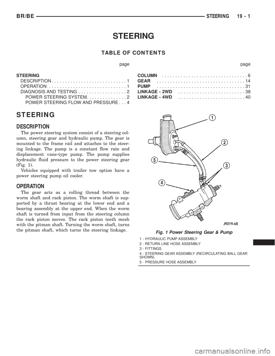
umn, steering gear and hydraulic pump. The gear is
mounted to the frame rail and attaches to the steer-
ing linkage. The pump is a constant flow rate and
displacement vane-type pump. The pump supplies
hydraulic fluid pressure to the power steering gear
(Fig. 1).
Vehicles equipped with trailer tow option have a
power steering pump oil cooler.
OPERATION
The gear acts as a rolling thread between the
worm shaft and rack piston. The worm shaft is sup-
ported by a thrust bearing at the lower end and a
bearing assembly at the upper end. When the worm
shaft is turned from input from the steering column
the rack piston moves. The rack piston teeth mesh
with the pitman shaft. Turning the worm shaft, turns
the pitman shaft, which turns the steering linkage.
Fig. 1 Power Steering Gear & Pump
1 - HYDRAULIC PUMP ASSEMBLY
2 - RETURN LINE HOSE ASSEMBLY
3 - FITTINGS
4 - STEERING GEAR ASSEMBLY (RECIRCULATING BALL GEAR
SHOWN)
5 - PRESSURE HOSE ASSEMBLY
BR/BESTEERING 19 - 1
Page 1595 of 2889

DIAGNOSIS AND TESTING - POWER STEERING SYSTEM
There is some noise in all power steering systems. One of the most common is a hissing sound evident at a
standstill parking. Or when the steering wheel is at the end of it's travel. Hiss is a high frequency noise similar
to that of a water tap being closed slowly. The noise is present in all valves that have a high velocity fluid passing
through an orifice. There is no relationship between this noise and steering performance.
STEERING NOISE
CONDITION POSSIBLE CAUSES CORRECTION
OBJECTIONAL HISS OR
WHISTLE1. Steering intermediate shaft to dash panel
seal.1. Check and repair seal at dash
panel.
2. Noisy valve in power steering gear. 2. Repair steering gear.
RATTLE OR CLUNK 1. Gear mounting bolts loose. 1. Tighten bolts to specification.
2. Loose or damaged suspension
components.2. Inspect and repair suspension.
3. Loose or damaged steering linkage. 3. Inspect and repair steering
linkage.
4. Internal gear noise. 4. Repair steering gear.
5. Pressure hose in contact with other
components.5. Reposition hose.
6. Loose or damaged intermediate shaft or
column.6. Inspect and repair or replace.
CHIRP OR SQUEAL 1. Loose belt. 1. Adjust or replace.
WHINE OR GROWL 1. Low fluid level. 1. Fill to proper level.
2. Pressure hose in contact with other
components.2. Reposition hose.
3. Internal pump noise. 3. Replace pump.
SUCKING AIR SOUND 1. Loose return line clamp. 1. Replace clamp.
2. O-ring missing or damaged on hose
fitting.2. Replace o-ring.
3. Low fluid level. 3. Fill to proper level.
4. Air leak between pump and reservoir. 4. Repair as necessary.
5. Reservoir cap not installed correctly. 5. Install reservoir cap correctly.
SCRUBBING OR
KNOCKING1. Wrong tire size. 1. Verify tire size.
2. Wrong gear. 2. Verify gear.
19 - 2 STEERINGBR/BE
STEERING (Continued)
Page 1596 of 2889

BINDING AND STICKING
CONDITION POSSIBLE CAUSE CORRECTION
DIFFICULT TO TURN WHEEL
STICKS OR BINDS1. Low fluid level. 1. Fill to proper level.
2. Tire pressure. 2. Adjust tire pressure.
3. Steering components (ball
joints/tie rod ends).3. Lube, inspect and repair as
necessary.
4. Loose belt. 4. Adjust or replace.
5. Low pump pressure. 5. Pressure test and replace if
necessary.
6. Column shaft coupler binding. 6. Replace coupler.
7. Steering gear worn or out of
adjustment.7. Repair or replace gear.
INSUFFICIENT ASST. OR POOR RETURN TO CENTER
CONDITION POSSIBLE CAUSE CORRECTION
HARD TURNING OR MOMENTARY
INCREASE IN TURNING EFFORT1. Tire pressure. 1. Adjust tire pressure.
2. Low fluid level. 2. Fill to proper level.
3. Loose belt. 3. Adjust or replace.
4. Lack of lubrication. 4. Inspect and lubricate steering and
suspension compnents.
5. Low pump pressure. 5. Pressure test and repair as
necessary.
6. Internal gear leak. 6. Pressure and flow test, and repair
as necessary.
STEERING WHEEL DOES NOT
WANT TO RETURN TO CENTER
POSITION1. Tire pressure. 1. Adjust tire pressure.
2. Wheel alignment. 2. Align front end.
3. Lack of lubrication. 3. Inspect and lubricate steering and
suspension compnents.
4. High friction in steering gear. 4. Test and adjust gear as
necessary.
LOOSE STEERING AND VEHICLE LEAD
CONDITION POSSIBLE CAUSE CORRECTION
EXCESSIVE PLAY IN STEERING
WHEEL1. Worn or loose suspension or
steering components.1. Inspect and repair as necessary.
2. Worn or loose wheel bearings. 2. Inspect and repair or adjust
bearings.
3. Steering gear mounting. 3. Tighten gear mounting bolts to
specification.
4. Gear out of adjustment. 4. Adjust gear to specification.
5. Worn or loose steering coupler. 5. Inspect and replace as
necessary.
BR/BESTEERING 19 - 3
STEERING (Continued)
Page 1597 of 2889
CONDITION POSSIBLE CAUSE CORRECTION
VEHICLE PULLS OR LEADS TO
ONE SIDE.1. Tire Pressure. 1. Adjust tire pressure.
2. Radial tire lead. 2. Rotate tires.
3. Brakes dragging. 3. Repair as necessary.
4. Wheel alignment. 4. Align front end.
DIAGNOSIS AND TESTING - POWER STEERING
FLOW AND PRESSURE
The following procedure is used to test the opera-
tion of the power steering system on the vehicle. This
test will provide the flow rate of the power steering
pump along with the maximum relief pressure. Per-
form test any time a power steering system problem
is present. This test will determine if the power
steering pump or power steering gear is not function-
ing properly. The following pressure and flow test is
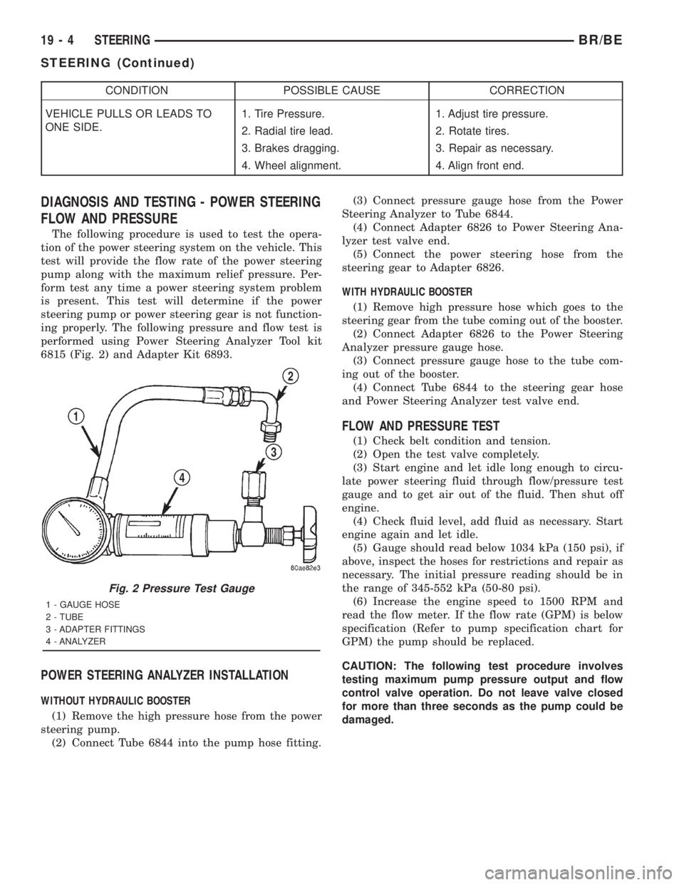
performed using Power Steering Analyzer Tool kit
6815 (Fig. 2) and Adapter Kit 6893.
POWER STEERING ANALYZER INSTALLATION
WITHOUT HYDRAULIC BOOSTER
(1) Remove the high pressure hose from the power
steering pump.
(2) Connect Tube 6844 into the pump hose fitting.(3) Connect pressure gauge hose from the Power
Steering Analyzer to Tube 6844.
(4) Connect Adapter 6826 to Power Steering Ana-
lyzer test valve end.
(5) Connect the power steering hose from the
steering gear to Adapter 6826.
WITH HYDRAULIC BOOSTER
(1) Remove high pressure hose which goes to the
steering gear from the tube coming out of the booster.
(2) Connect Adapter 6826 to the Power Steering
Analyzer pressure gauge hose.
(3) Connect pressure gauge hose to the tube com-
ing out of the booster.
(4) Connect Tube 6844 to the steering gear hose
and Power Steering Analyzer test valve end.
FLOW AND PRESSURE TEST
(1) Check belt condition and tension.
(2) Open the test valve completely.
(3) Start engine and let idle long enough to circu-
late power steering fluid through flow/pressure test
gauge and to get air out of the fluid. Then shut off
engine.
(4) Check fluid level, add fluid as necessary. Start
engine again and let idle.
(5) Gauge should read below 1034 kPa (150 psi), if
above, inspect the hoses for restrictions and repair as
necessary. The initial pressure reading should be in
the range of 345-552 kPa (50-80 psi).
(6) Increase the engine speed to 1500 RPM and
read the flow meter. If the flow rate (GPM) is below
specification (Refer to pump specification chart for
GPM) the pump should be replaced.
CAUTION: The following test procedure involves
testing maximum pump pressure output and flow
control valve operation. Do not leave valve closed
for more than three seconds as the pump could be
damaged.
Fig. 2 Pressure Test Gauge
1 - GAUGE HOSE
2 - TUBE
3 - ADAPTER FITTINGS
4 - ANALYZER
19 - 4 STEERINGBR/BE
STEERING (Continued)