2001 DODGE RAM steering
[x] Cancel search: steeringPage 1624 of 2889
PUMP
TABLE OF CONTENTS
page page
PUMP
DESCRIPTION...........................31
OPERATION.............................31
DIAGNOSIS AND TESTING.................31
PUMP LEAKAGE.......................31
STANDARD PROCEDURE..................31
POWER STEERING PUMP - INITIAL
OPERATION...........................31
FLUSHING POWER STEERING SYSTEM.....32
REMOVAL..............................33
INSTALLATION...........................35SPECIAL TOOLS.........................36
PULLEY
REMOVAL..............................36
INSTALLATION...........................36
HOSES - PRESSURE
DESCRIPTION...........................37
OPERATION.............................37
HOSES - RETURN
DESCRIPTION...........................37
OPERATION.............................37
PUMP
DESCRIPTION
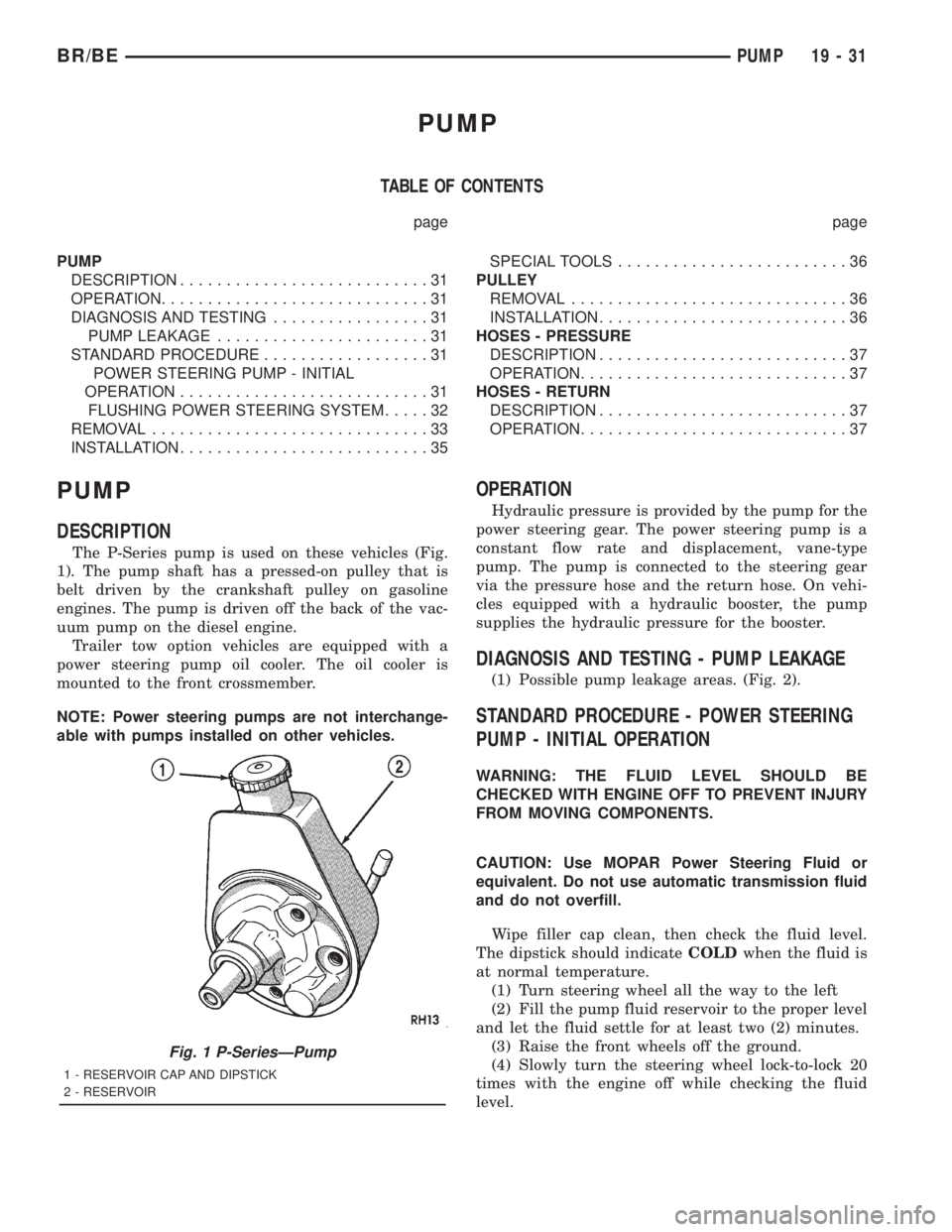
The P-Series pump is used on these vehicles (Fig.
1). The pump shaft has a pressed-on pulley that is
belt driven by the crankshaft pulley on gasoline
engines. The pump is driven off the back of the vac-
uum pump on the diesel engine.
Trailer tow option vehicles are equipped with a
power steering pump oil cooler. The oil cooler is
mounted to the front crossmember.
NOTE: Power steering pumps are not interchange-
able with pumps installed on other vehicles.
OPERATION
Hydraulic pressure is provided by the pump for the
power steering gear. The power steering pump is a
constant flow rate and displacement, vane-type
pump. The pump is connected to the steering gear
via the pressure hose and the return hose. On vehi-
cles equipped with a hydraulic booster, the pump
supplies the hydraulic pressure for the booster.
DIAGNOSIS AND TESTING - PUMP LEAKAGE
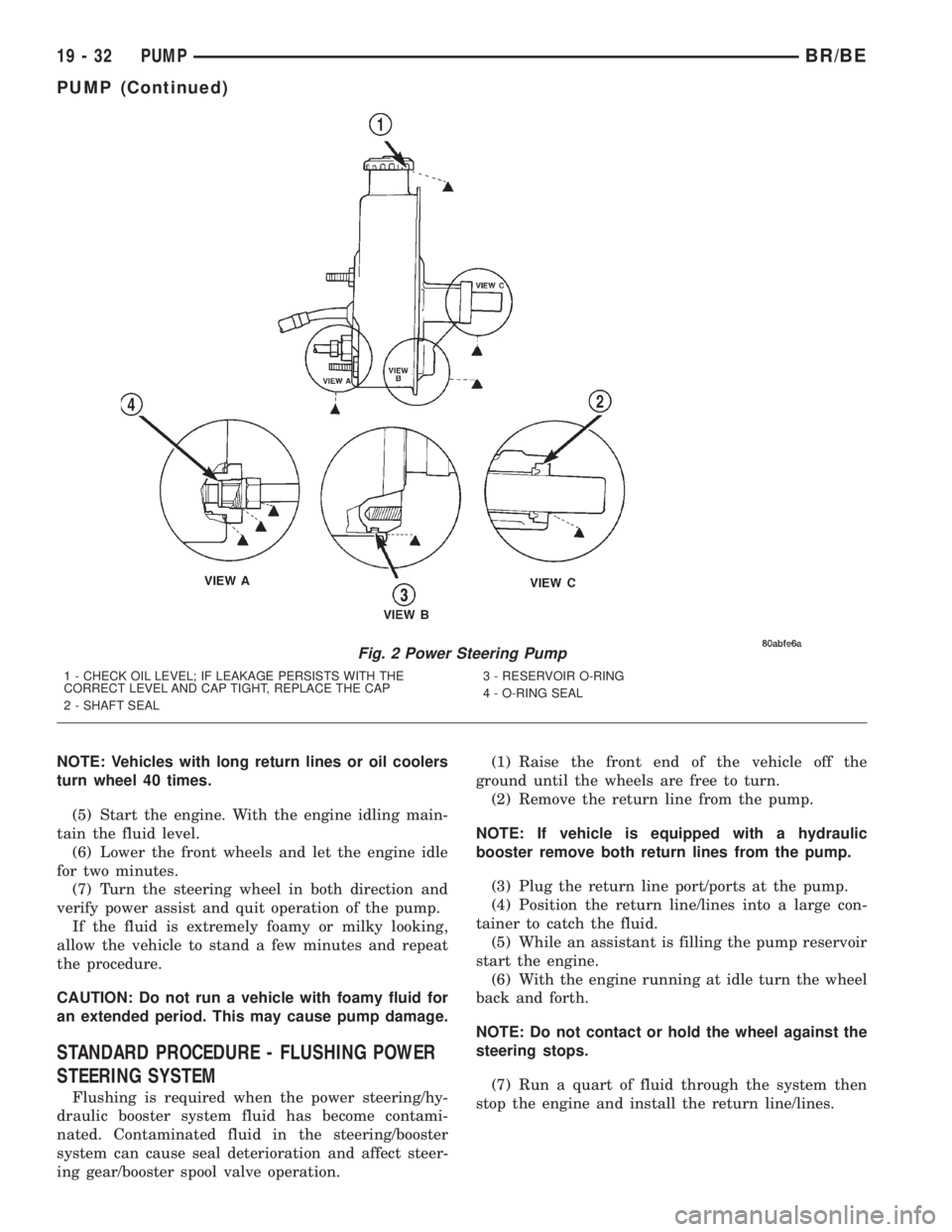
(1) Possible pump leakage areas. (Fig. 2).
STANDARD PROCEDURE - POWER STEERING
PUMP - INITIAL OPERATION
WARNING: THE FLUID LEVEL SHOULD BE
CHECKED WITH ENGINE OFF TO PREVENT INJURY
FROM MOVING COMPONENTS.
CAUTION: Use MOPAR Power Steering Fluid or
equivalent. Do not use automatic transmission fluid
and do not overfill.
Wipe filler cap clean, then check the fluid level.
The dipstick should indicateCOLDwhen the fluid is
at normal temperature.
(1) Turn steering wheel all the way to the left
(2) Fill the pump fluid reservoir to the proper level
and let the fluid settle for at least two (2) minutes.
(3) Raise the front wheels off the ground.
(4) Slowly turn the steering wheel lock-to-lock 20
times with the engine off while checking the fluid
level.
Fig. 1 P-SeriesÐPump
1 - RESERVOIR CAP AND DIPSTICK
2 - RESERVOIR
BR/BEPUMP 19 - 31
Page 1625 of 2889
NOTE: Vehicles with long return lines or oil coolers
turn wheel 40 times.
(5) Start the engine. With the engine idling main-
tain the fluid level.
(6) Lower the front wheels and let the engine idle
for two minutes.
(7) Turn the steering wheel in both direction and
verify power assist and quit operation of the pump.
If the fluid is extremely foamy or milky looking,
allow the vehicle to stand a few minutes and repeat
the procedure.
CAUTION: Do not run a vehicle with foamy fluid for
an extended period. This may cause pump damage.
STANDARD PROCEDURE - FLUSHING POWER
STEERING SYSTEM
Flushing is required when the power steering/hy-
draulic booster system fluid has become contami-
nated. Contaminated fluid in the steering/booster
system can cause seal deterioration and affect steer-
ing gear/booster spool valve operation.(1) Raise the front end of the vehicle off the
ground until the wheels are free to turn.
(2) Remove the return line from the pump.
NOTE: If vehicle is equipped with a hydraulic
booster remove both return lines from the pump.
(3) Plug the return line port/ports at the pump.
(4) Position the return line/lines into a large con-
tainer to catch the fluid.
(5) While an assistant is filling the pump reservoir
start the engine.
(6) With the engine running at idle turn the wheel
back and forth.
NOTE: Do not contact or hold the wheel against the
steering stops.
(7) Run a quart of fluid through the system then
stop the engine and install the return line/lines.
Fig. 2 Power Steering Pump
1 - CHECK OIL LEVEL; IF LEAKAGE PERSISTS WITH THE
CORRECT LEVEL AND CAP TIGHT, REPLACE THE CAP
2 - SHAFT SEAL3 - RESERVOIR O-RING
4 - O-RING SEAL
19 - 32 PUMPBR/BE
PUMP (Continued)
Page 1626 of 2889
(8) Fill the system with fluid and perform Steering
Pump Initial Operation, (Refer to 19 - STEERING/
PUMP - STANDARD PROCEDURE).
(9) Start the engine and run it for fifteen minutes
then stop the engine.
(10) Remove the return line/lines from the pump
and plug the pump port/ports.
(11) Pour fresh fluid into the reservoir and check
the draining fluid for contamination. If the fluid is
still contaminated, disassemble and clean the steer-
ing gear and flush the system again.
(12) Install the return line/lines and perform
Steering Pump Initial Operation, (Refer to 19 -
STEERING/PUMP - STANDARD PROCEDURE).
REMOVAL - GASOLINE ENGINE
(1) Remove the serpentine drive belt, (Refer to 7 -
COOLING/ACCESSORY DRIVE/DRIVE BELTS -
REMOVAL) OR (Refer to 7 - COOLING/ACCESSORY
DRIVE/DRIVE BELTS - REMOVAL).
(2) Remove the hoses from the power steering
pump and cap the fittings.
(3) Remove battery ground cable and unthread
stud from cylinder head, do not remove from bracket.
(4) Loosen upper bracket bolt and remove the
lower bracket to engine block bolts.
(5) Pivot the pump assembly past the coolant tube.
(6) Remove the upper stud and remove upper bolt
from cylinder head.
(7) Remove steering pump and mounting bracket
from engine as an assembly.
(8) Remove the pump pulley with Puller C-4333, to
access pump attaching bolts, (Refer to 19 - STEER-
ING/PUMP/PULLEY - REMOVAL).
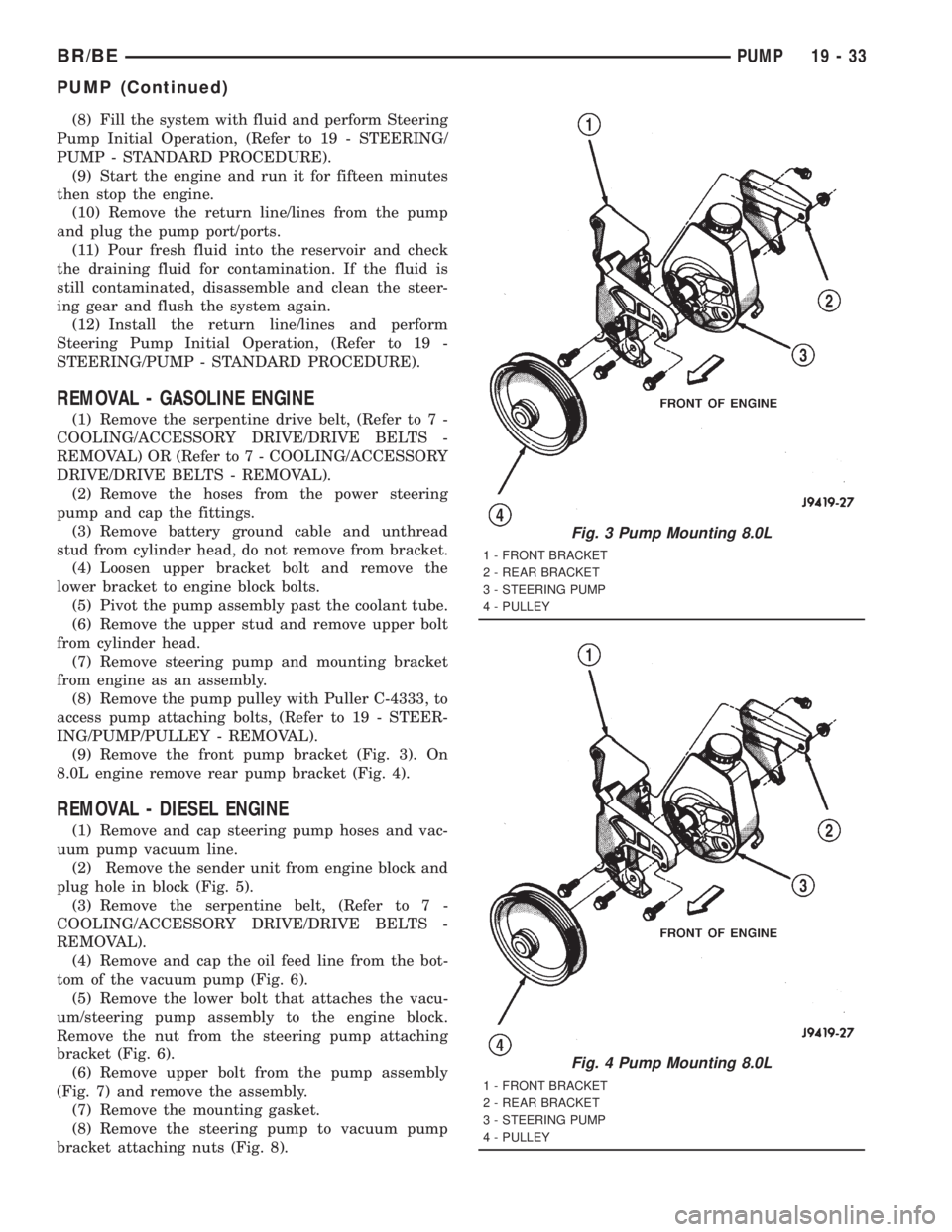
(9) Remove the front pump bracket (Fig. 3). On
8.0L engine remove rear pump bracket (Fig. 4).
REMOVAL - DIESEL ENGINE
(1) Remove and cap steering pump hoses and vac-
uum pump vacuum line.
(2) Remove the sender unit from engine block and
plug hole in block (Fig. 5).
(3) Remove the serpentine belt, (Refer to 7 -
COOLING/ACCESSORY DRIVE/DRIVE BELTS -
REMOVAL).
(4) Remove and cap the oil feed line from the bot-
tom of the vacuum pump (Fig. 6).
(5) Remove the lower bolt that attaches the vacu-
um/steering pump assembly to the engine block.
Remove the nut from the steering pump attaching
bracket (Fig. 6).
(6) Remove upper bolt from the pump assembly
(Fig. 7) and remove the assembly.
(7) Remove the mounting gasket.
(8) Remove the steering pump to vacuum pump
bracket attaching nuts (Fig. 8).
Fig. 3 Pump Mounting 8.0L
1 - FRONT BRACKET
2 - REAR BRACKET
3 - STEERING PUMP
4 - PULLEY
Fig. 4 Pump Mounting 8.0L
1 - FRONT BRACKET
2 - REAR BRACKET
3 - STEERING PUMP
4 - PULLEY
BR/BEPUMP 19 - 33
PUMP (Continued)
Page 1627 of 2889
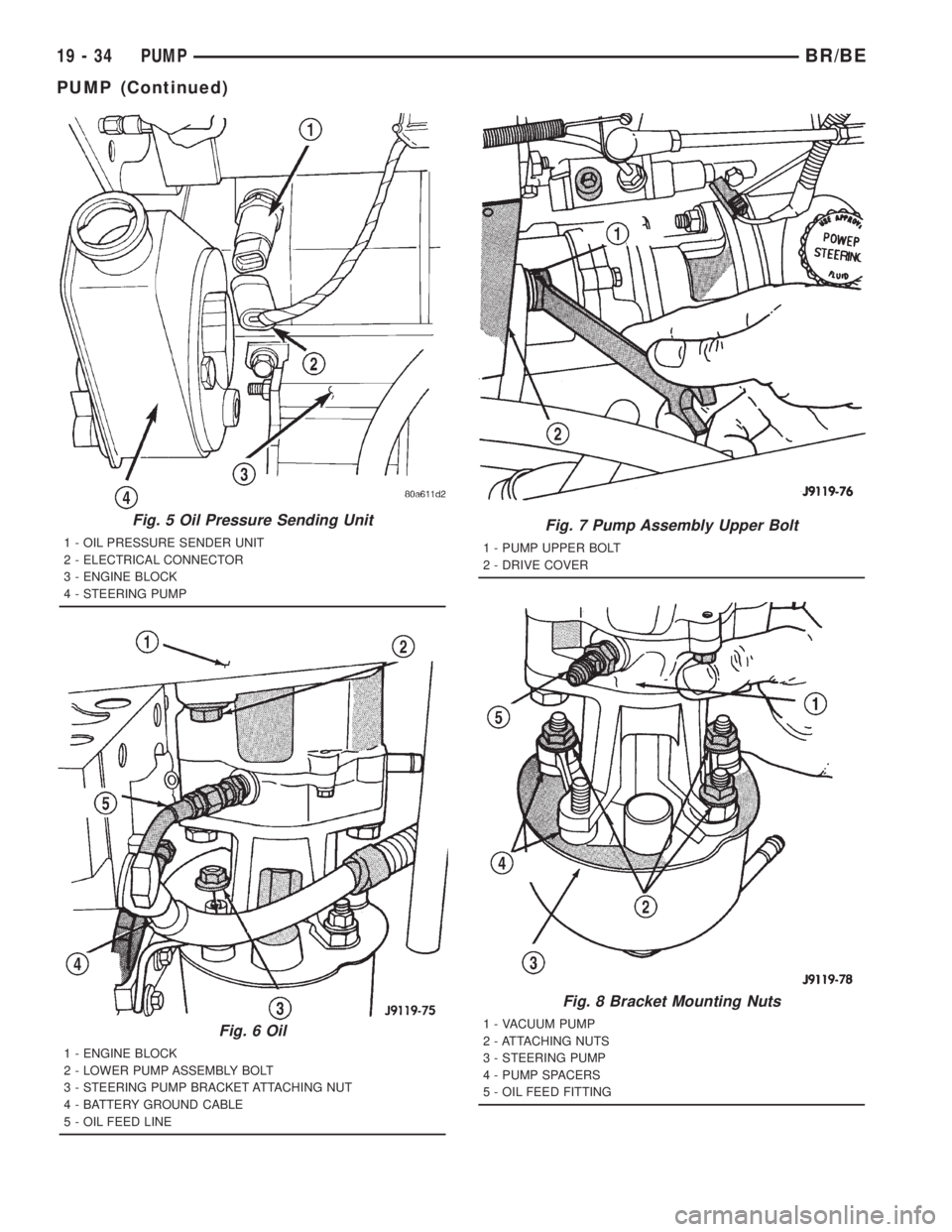
Fig. 5 Oil Pressure Sending Unit
1 - OIL PRESSURE SENDER UNIT
2 - ELECTRICAL CONNECTOR
3 - ENGINE BLOCK
4 - STEERING PUMP
Fig. 6 Oil
1 - ENGINE BLOCK
2 - LOWER PUMP ASSEMBLY BOLT
3 - STEERING PUMP BRACKET ATTACHING NUT
4 - BATTERY GROUND CABLE
5 - OIL FEED LINE
Fig. 7 Pump Assembly Upper Bolt
1 - PUMP UPPER BOLT
2 - DRIVE COVER
Fig. 8 Bracket Mounting Nuts
1 - VACUUM PUMP
2 - ATTACHING NUTS
3 - STEERING PUMP
4 - PUMP SPACERS
5 - OIL FEED FITTING
19 - 34 PUMPBR/BE
PUMP (Continued)
Page 1628 of 2889
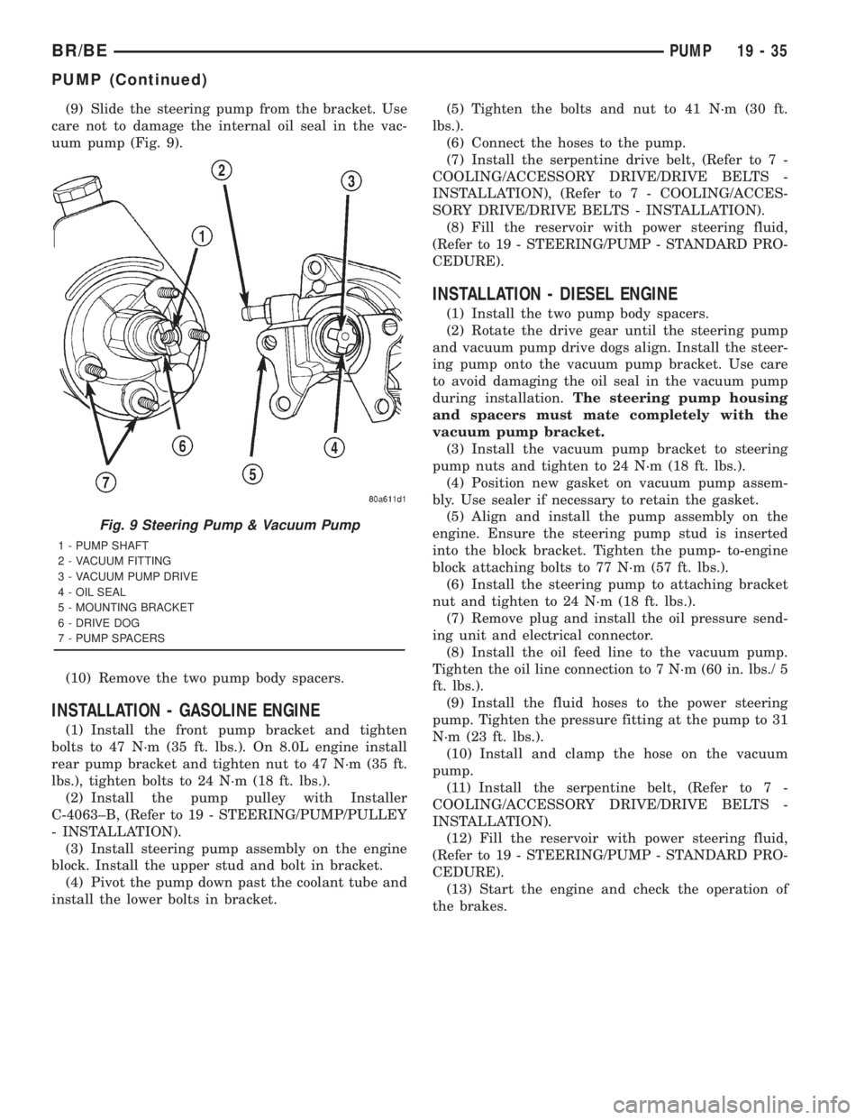
(9) Slide the steering pump from the bracket. Use
care not to damage the internal oil seal in the vac-
uum pump (Fig. 9).
(10) Remove the two pump body spacers.
INSTALLATION - GASOLINE ENGINE
(1) Install the front pump bracket and tighten
bolts to 47 N´m (35 ft. lbs.). On 8.0L engine install
rear pump bracket and tighten nut to 47 N´m (35 ft.
lbs.), tighten bolts to 24 N´m (18 ft. lbs.).
(2) Install the pump pulley with Installer
C-4063±B, (Refer to 19 - STEERING/PUMP/PULLEY
- INSTALLATION).
(3) Install steering pump assembly on the engine
block. Install the upper stud and bolt in bracket.
(4) Pivot the pump down past the coolant tube and
install the lower bolts in bracket.(5) Tighten the bolts and nut to 41 N´m (30 ft.
lbs.).
(6) Connect the hoses to the pump.
(7) Install the serpentine drive belt, (Refer to 7 -
COOLING/ACCESSORY DRIVE/DRIVE BELTS -
INSTALLATION), (Refer to 7 - COOLING/ACCES-
SORY DRIVE/DRIVE BELTS - INSTALLATION).
(8) Fill the reservoir with power steering fluid,
(Refer to 19 - STEERING/PUMP - STANDARD PRO-
CEDURE).
INSTALLATION - DIESEL ENGINE
(1) Install the two pump body spacers.
(2) Rotate the drive gear until the steering pump
and vacuum pump drive dogs align. Install the steer-
ing pump onto the vacuum pump bracket. Use care
to avoid damaging the oil seal in the vacuum pump
during installation.The steering pump housing
and spacers must mate completely with the
vacuum pump bracket.
(3) Install the vacuum pump bracket to steering
pump nuts and tighten to 24 N´m (18 ft. lbs.).
(4) Position new gasket on vacuum pump assem-
bly. Use sealer if necessary to retain the gasket.
(5) Align and install the pump assembly on the
engine. Ensure the steering pump stud is inserted
into the block bracket. Tighten the pump- to-engine
block attaching bolts to 77 N´m (57 ft. lbs.).
(6) Install the steering pump to attaching bracket
nut and tighten to 24 N´m (18 ft. lbs.).
(7) Remove plug and install the oil pressure send-
ing unit and electrical connector.
(8) Install the oil feed line to the vacuum pump.
Tighten the oil line connection to 7 N´m (60 in. lbs./ 5
ft. lbs.).
(9) Install the fluid hoses to the power steering
pump. Tighten the pressure fitting at the pump to 31
N´m (23 ft. lbs.).
(10) Install and clamp the hose on the vacuum
pump.
(11) Install the serpentine belt, (Refer to 7 -
COOLING/ACCESSORY DRIVE/DRIVE BELTS -
INSTALLATION).
(12) Fill the reservoir with power steering fluid,
(Refer to 19 - STEERING/PUMP - STANDARD PRO-
CEDURE).
(13) Start the engine and check the operation of
the brakes.
Fig. 9 Steering Pump & Vacuum Pump
1 - PUMP SHAFT
2 - VACUUM FITTING
3 - VACUUM PUMP DRIVE
4 - OIL SEAL
5 - MOUNTING BRACKET
6 - DRIVE DOG
7 - PUMP SPACERS
BR/BEPUMP 19 - 35
PUMP (Continued)
Page 1629 of 2889
SPECIAL TOOLS
POWER STEERING PUMP
PULLEY
REMOVAL
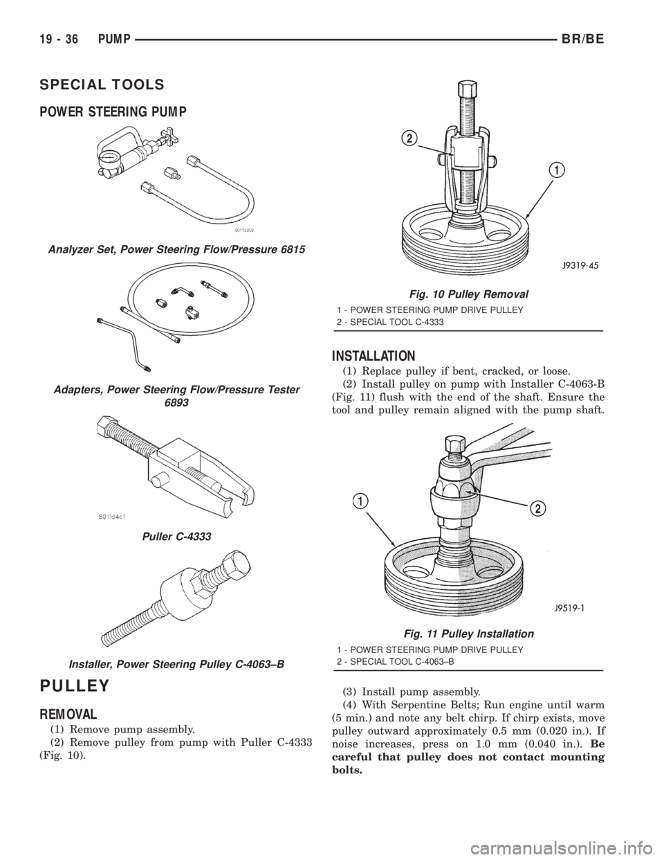
(1) Remove pump assembly.
(2) Remove pulley from pump with Puller C-4333
(Fig. 10).
INSTALLATION
(1) Replace pulley if bent, cracked, or loose.
(2) Install pulley on pump with Installer C-4063-B
(Fig. 11) flush with the end of the shaft. Ensure the
tool and pulley remain aligned with the pump shaft.
(3) Install pump assembly.
(4) With Serpentine Belts; Run engine until warm
(5 min.) and note any belt chirp. If chirp exists, move
pulley outward approximately 0.5 mm (0.020 in.). If
noise increases, press on 1.0 mm (0.040 in.).Be
careful that pulley does not contact mounting
bolts.
Analyzer Set, Power Steering Flow/Pressure 6815
Adapters, Power Steering Flow/Pressure Tester
6893
Puller C-4333
Installer, Power Steering Pulley C-4063±B
Fig. 10 Pulley Removal
1 - POWER STEERING PUMP DRIVE PULLEY
2 - SPECIAL TOOL C-4333
Fig. 11 Pulley Installation
1 - POWER STEERING PUMP DRIVE PULLEY
2 - SPECIAL TOOL C-4063±B
19 - 36 PUMPBR/BE
Page 1630 of 2889
HOSES - PRESSURE
DESCRIPTION
The hose consists of two metal ends and rubber
center section that contains a tuning cable.
OPERATION
Power steering pressure line, is used to transfer
high pressure power steering fluid, from the power
steering pump to the power steering gear.
HOSES - RETURN
DESCRIPTION
Power steering return line is a hose which is
clamped at the pump and the gear.
OPERATION
Power steering return line, is used to transfer low
pressure power steering fluid, from the power steer-
ing gear to the power steering pump.
BR/BEPUMP 19 - 37
Page 1631 of 2889
LINKAGE - 2WD
TABLE OF CONTENTS
page page
LINKAGE - 2WD
DESCRIPTION...........................38
STANDARD PROCEDURE..................38
LUBRICATION.........................38REMOVAL..............................38
INSTALLATION...........................39
SPECIFICATIONS........................39
SPECIAL TOOLS.........................39
LINKAGE - 2WD
DESCRIPTION
Light duty (LD) and heavy duty (HD) steering link-
age is used with IFS suspensions. The linkage is
comprised of a idler arm, pitman arm, center link
and tie rod ends. Heavy duty linkage is used on 8800
and 10500 lb. GVW vehicles.
CAUTION: If any steering components are replaced
or serviced an alignment must be performed.
NOTE: When servicing the steering linkage, use
care to avoid damaging ball stud seals. Use Puller
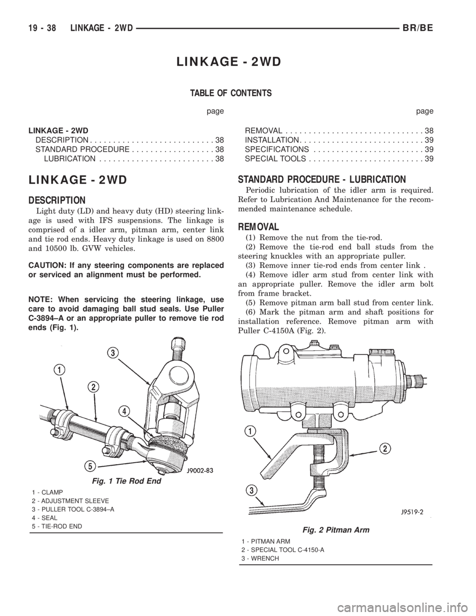
C-3894±A or an appropriate puller to remove tie rod
ends (Fig. 1).
STANDARD PROCEDURE - LUBRICATION
Periodic lubrication of the idler arm is required.
Refer to Lubrication And Maintenance for the recom-
mended maintenance schedule.
REMOVAL
(1) Remove the nut from the tie-rod.
(2) Remove the tie-rod end ball studs from the
steering knuckles with an appropriate puller.
(3) Remove inner tie-rod ends from center link .
(4) Remove idler arm stud from center link with
an appropriate puller. Remove the idler arm bolt
from frame bracket.
(5) Remove pitman arm ball stud from center link.
(6) Mark the pitman arm and shaft positions for
installation reference. Remove pitman arm with
Puller C-4150A (Fig. 2).
Fig. 1 Tie Rod End
1 - CLAMP
2 - ADJUSTMENT SLEEVE
3 - PULLER TOOL C-3894±A
4 - SEAL
5 - TIE-ROD END
Fig. 2 Pitman Arm
1 - PITMAN ARM
2 - SPECIAL TOOL C-4150-A
3 - WRENCH
19 - 38 LINKAGE - 2WDBR/BE