Page 1606 of 2889
GEAR SHIFT LEVER
REMOVAL
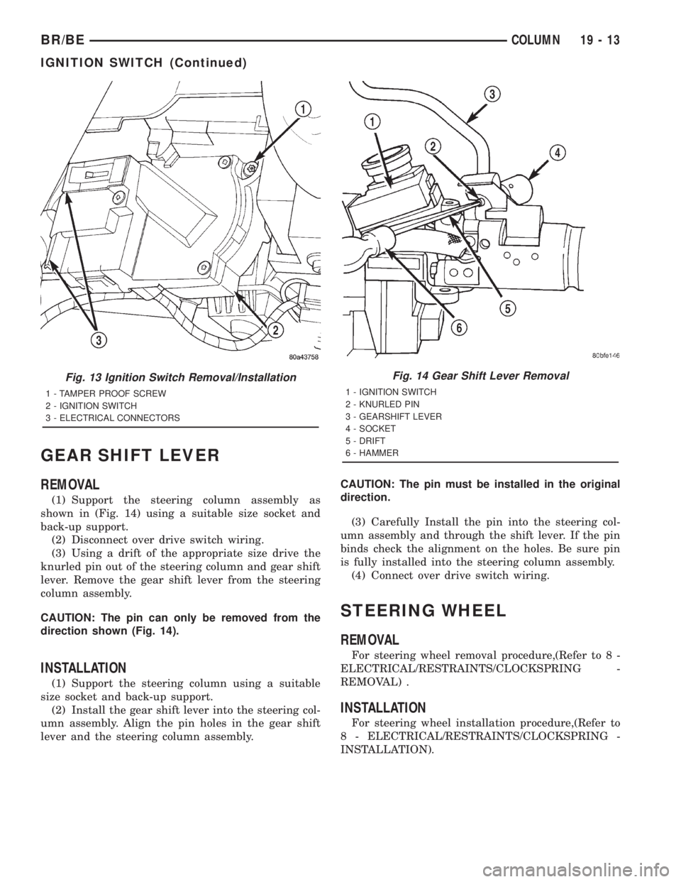
(1) Support the steering column assembly as
shown in (Fig. 14) using a suitable size socket and
back-up support.
(2) Disconnect over drive switch wiring.
(3) Using a drift of the appropriate size drive the
knurled pin out of the steering column and gear shift
lever. Remove the gear shift lever from the steering
column assembly.
CAUTION: The pin can only be removed from the
direction shown (Fig. 14).
INSTALLATION
(1) Support the steering column using a suitable
size socket and back-up support.
(2) Install the gear shift lever into the steering col-
umn assembly. Align the pin holes in the gear shift
lever and the steering column assembly.CAUTION: The pin must be installed in the original
direction.
(3) Carefully Install the pin into the steering col-
umn assembly and through the shift lever. If the pin
binds check the alignment on the holes. Be sure pin
is fully installed into the steering column assembly.
(4) Connect over drive switch wiring.
STEERING WHEEL
REMOVAL
For steering wheel removal procedure,(Refer to 8 -
ELECTRICAL/RESTRAINTS/CLOCKSPRING -
REMOVAL) .
INSTALLATION
For steering wheel installation procedure,(Refer to
8 - ELECTRICAL/RESTRAINTS/CLOCKSPRING -
INSTALLATION).
Fig. 13 Ignition Switch Removal/Installation
1 - TAMPER PROOF SCREW
2 - IGNITION SWITCH
3 - ELECTRICAL CONNECTORS
Fig. 14 Gear Shift Lever Removal
1 - IGNITION SWITCH
2 - KNURLED PIN
3 - GEARSHIFT LEVER
4 - SOCKET
5 - DRIFT
6 - HAMMER
BR/BECOLUMN 19 - 13
IGNITION SWITCH (Continued)
Page 1607 of 2889
GEAR
TABLE OF CONTENTS
page page
GEAR
DESCRIPTION...........................14
OPERATION.............................14
DIAGNOSIS AND TESTING.................14
POWER STEERING GEAR LEAKAGE.......14
REMOVAL..............................16
INSTALLATION...........................16
ADJUSTMENTS..........................16
SPECIFICATIONS........................19
SPECIAL TOOLS.........................20
PITMAN BEARING
REMOVAL..............................20
INSTALLATION...........................21
PITMAN SHAFT
REMOVAL..............................22INSTALLATION...........................23
PITMAN SHAFT SEAL
REMOVAL..............................23
INSTALLATION...........................24
SPOOL VALVE
REMOVAL..............................24
INSTALLATION...........................26
STEERING GEAR HOUSING PLUG
REMOVAL..............................27
INSTALLATION...........................27
WORM SHAFT
REMOVAL..............................27
INSTALLATION...........................29
GEAR
DESCRIPTION
The power steering gear is a recirculating ball type
gear (Fig. 1). The gear ratio's used are 17.5:1 and
14:1.
OPERATION
The gear acts as a rolling thread between the
worm shaft and rack piston. The worm shaft is sup-
ported by a thrust bearing at the lower end and abearing assembly at the upper end. When the worm
shaft is turned from input from the steering column
the rack piston moves. The rack piston teeth mesh
with the pitman shaft. Turning the worm shaft, turns
the pitman shaft, which turns the steering linkage.
DIAGNOSIS AND TESTING - POWER STEERING
GEAR LEAKAGE
(1) Possible power steering gear leakage areas.
(Fig. 2).
19 - 14 GEARBR/BE
Page 1608 of 2889
Fig. 1 Power Steering Gear
1 - THRUST BEARING
2 - O-RING SEAL
3 - INLET
4 - OUTLET
5 - SEAL
6 - TORSION BAR
7 - STUB SHAFT
8 - ADJUSTER PLUG
9 - THRUST BEARING10 - TEFLON SEALS
11 - SPOOL VALVE
12 - VALVE BODY
13 - WORMSHAFT
14 - PIN
15 - PITMAN SHAFT
16 - RACK PISTON
17 - TEFLON RING
BR/BEGEAR 19 - 15
GEAR (Continued)
Page 1609 of 2889

REMOVAL
(1) Place the front wheels in a straight-ahead posi-
tion.
(2) Disconnect and cap the fluid hoses from steer-
ing gear.
(3) Remove coupler pinch bolt at the steering gear
and slide shaft off gear (Fig. 3).
(4) Mark the pitman shaft and pitman arm for
installation reference. Remove the pitman arm from
the shaft with Puller C-4150A (Fig. 4).(5) Remove steering gear retaining bolts and nuts.
Remove the steering gear from the vehicle.INSTALLATION
(1) Position the steering gear on the frame rail and
install the bolts. Tighten mounting bolts to specifica-
tions.
(2) Align steering coupler on gear shaft. Install
pinch bolt and tighten to 49 N´m (36 ft. lbs.) torque.
(3) Align and install the pitman arm.
(4) Install the washer and retaining nut on the pit-
man shaft. Tighten the nut to 251 N´m (185 ft. lbs.).
(5) Connect fluid hoses to steering gear, tighten to
31 N´m (23 ft. lbs.). Add fluid, (Refer to 19 - STEER-
ING/PUMP - STANDARD PROCEDURE).
ADJUSTMENTS
CAUTION: Steering gear must be adjusted in the
proper order. If adjustments are not performed in
order, gear damage and improper steering response
may result.
NOTE: Adjusting the steering gear in the vehicle is
not recommended. Remove gear from the vehicle
and drain the fluid. Then mount gear in a vise to
perform adjustments.
Fig. 2 STEERING GEAR
Fig. 3 Column Shaft
1 - STEERING GEAR
2 - STEERING COUPLER
Fig. 4 Pitman Arm
1 - PITMAN ARM
2 - SPECIAL TOOL C-4150-A
3 - WRENCH
19 - 16 GEARBR/BE
GEAR (Continued)
Page 1610 of 2889
WORM THRUST BEARING PRELOAD
(1) Mount the gear carefully into a vise.
CAUTION: Do not overtighten the vise on the gear
case. This may affect the adjustment
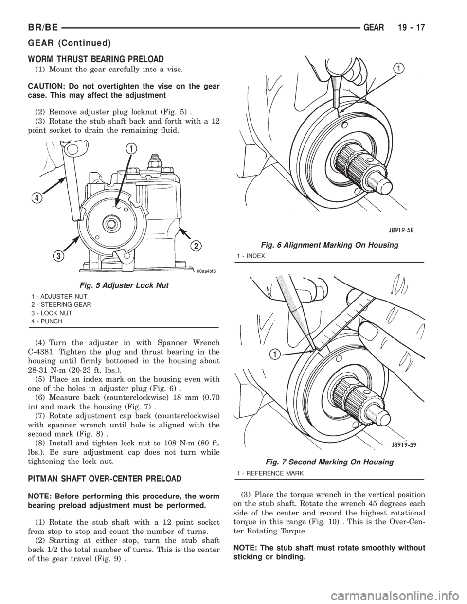
(2) Remove adjuster plug locknut (Fig. 5) .
(3) Rotate the stub shaft back and forth with a 12
point socket to drain the remaining fluid.
(4) Turn the adjuster in with Spanner Wrench
C-4381. Tighten the plug and thrust bearing in the
housing until firmly bottomed in the housing about
28-31 N´m (20-23 ft. lbs.).
(5) Place an index mark on the housing even with
one of the holes in adjuster plug (Fig. 6) .
(6) Measure back (counterclockwise) 18 mm (0.70
in) and mark the housing (Fig. 7) .
(7) Rotate adjustment cap back (counterclockwise)
with spanner wrench until hole is aligned with the
second mark (Fig. 8) .
(8) Install and tighten lock nut to 108 N´m (80 ft.
lbs.). Be sure adjustment cap does not turn while
tightening the lock nut.
PITMAN SHAFT OVER-CENTER PRELOAD
NOTE: Before performing this procedure, the worm
bearing preload adjustment must be performed.
(1) Rotate the stub shaft with a 12 point socket
from stop to stop and count the number of turns.
(2) Starting at either stop, turn the stub shaft
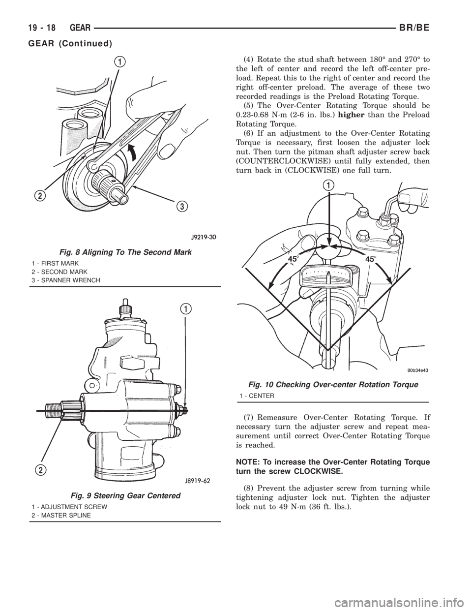
back 1/2 the total number of turns. This is the center
of the gear travel (Fig. 9) .(3) Place the torque wrench in the vertical position
on the stub shaft. Rotate the wrench 45 degrees each
side of the center and record the highest rotational
torque in this range (Fig. 10) . This is the Over-Cen-
ter Rotating Torque.
NOTE: The stub shaft must rotate smoothly without
sticking or binding.
Fig. 5 Adjuster Lock Nut
1 - ADJUSTER NUT
2 - STEERING GEAR
3 - LOCK NUT
4 - PUNCH
Fig. 6 Alignment Marking On Housing
1 - INDEX
Fig. 7 Second Marking On Housing
1 - REFERENCE MARK
BR/BEGEAR 19 - 17
GEAR (Continued)
Page 1611 of 2889
(4) Rotate the stud shaft between 180É and 270É to
the left of center and record the left off-center pre-
load. Repeat this to the right of center and record the
right off-center preload. The average of these two
recorded readings is the Preload Rotating Torque.
(5) The Over-Center Rotating Torque should be
0.23-0.68 N´m (2-6 in. lbs.)higherthan the Preload
Rotating Torque.
(6) If an adjustment to the Over-Center Rotating
Torque is necessary, first loosen the adjuster lock
nut. Then turn the pitman shaft adjuster screw back
(COUNTERCLOCKWISE) until fully extended, then
turn back in (CLOCKWISE) one full turn.
(7) Remeasure Over-Center Rotating Torque. If
necessary turn the adjuster screw and repeat mea-
surement until correct Over-Center Rotating Torque
is reached.
NOTE: To increase the Over-Center Rotating Torque
turn the screw CLOCKWISE.
(8) Prevent the adjuster screw from turning while
tightening adjuster lock nut. Tighten the adjuster
lock nut to 49 N´m (36 ft. lbs.).
Fig. 8 Aligning To The Second Mark
1 - FIRST MARK
2 - SECOND MARK
3 - SPANNER WRENCH
Fig. 9 Steering Gear Centered
1 - ADJUSTMENT SCREW
2 - MASTER SPLINE
Fig. 10 Checking Over-center Rotation Torque
1 - CENTER
19 - 18 GEARBR/BE
GEAR (Continued)
Page 1612 of 2889
SPECIFICATIONS
POWER STEERING GEAR
SPECIFICATIONS
DESCRIPTION SPECIFICATION
Steering Gear
TypeRecirculating Ball
DESCRIPTION SPECIFICATION
Gear Code & Ratio
AM17.5:1
Gear Code & Ratio
HC/FW14:1
Gear Code & Ratio
JZ16-13:1
TORQUE SPECIFICATIONS
DESCRIPTION N´m Ft. Lbs. In. Lbs.
Wormshaft Bearing
Preload0.85-1.64 Ð 7.5-14.5
Pitman Shaft Overcenter Drag
New Gear (under 400 miles)0.23-0.68 Ð 2-6
+ Wormshaft Preload
TORQUE CHART
TORQUE SPECIFICATIONS
DESCRIPTION N´m Ft. Lbs. In. Lbs.
Steering Gear Mounting
Frame Bolts176 130 Ð
Line Fittings
Pressure31 23 Ð
Line Fittings
Return31 23 Ð
Steering Gear
Adjustment Cap Locknut108 80 Ð
Steering Gear
Adjustment Screw Locknut49 36 Ð
Steering Gear
Pitman Shaft Nut251 185 Ð
Steering Gear
Rack Piston Plug150 111 Ð
Steering Gear
Side Cover Bolts60 44 Ð
Steering Gear
Return Guide Clamp Bolt4.8 Ð 43
BR/BEGEAR 19 - 19
Page 1613 of 2889
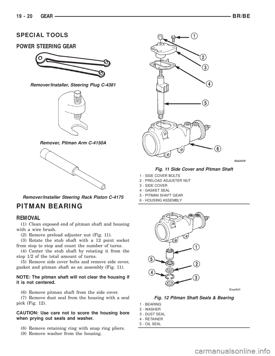
SPECIAL TOOLS
POWER STEERING GEAR
PITMAN BEARING
REMOVAL
(1) Clean exposed end of pitman shaft and housing
with a wire brush.
(2) Remove preload adjuster nut (Fig. 11).
(3) Rotate the stub shaft with a 12 point socket
from stop to stop and count the number of turns.
(4) Center the stub shaft by rotating it from the
stop 1/2 of the total amount of turns.
(5) Remove side cover bolts and remove side cover,
gasket and pitman shaft as an assembly (Fig. 11).
NOTE: The pitman shaft will not clear the housing if
it is not centered.
(6) Remove pitman shaft from the side cover.
(7) Remove dust seal from the housing with a seal
pick (Fig. 12).
CAUTION: Use care not to score the housing bore
when prying out seals and washer.
(8) Remove retaining ring with snap ring pliers.
(9) Remove washer from the housing.
Remover/Installer, Steering Plug C-4381
Remover, Pitman Arm C-4150A
Remover/Installer Steering Rack Piston C-4175
Fig. 11 Side Cover and Pitman Shaft
1 - SIDE COVER BOLTS
2 - PRELOAD ADJUSTER NUT
3 - SIDE COVER
4 - GASKET SEAL
5 - PITMAN SHAFT GEAR
6 - HOUSING ASSEMBLY
Fig. 12 Pitman Shaft Seals & Bearing
1 - BEARING
2 - WASHER
3 - DUST SEAL
4 - RETAINER
5 - OIL SEAL
19 - 20 GEARBR/BE