2001 DODGE RAM sensor
[x] Cancel search: sensorPage 1568 of 2889
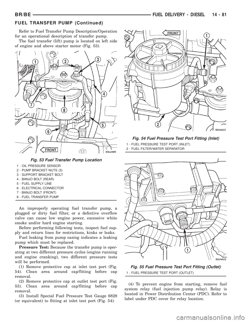
Refer to Fuel Transfer Pump Description/Operation
for an operational description of transfer pump.
The fuel transfer (lift) pump is located on left side
of engine and above starter motor (Fig. 53).
An improperly operating fuel transfer pump, a
plugged or dirty fuel filter, or a defective overflow
valve can cause low engine power, excessive white
smoke and/or hard engine starting.
Before performing following tests, inspect fuel sup-
ply and return lines for restrictions, kinks or leaks.
Fuel leaking from pump casing indicates a leaking
pump which must be replaced.
Pressure Test:Because the transfer pump is oper-
ating at two different pressure cycles (engine running
and engine cranking), two different pressure tests
will be performed.
(1) Remove protective cap at inlet test port (Fig.
54). Clean area around cap/fitting before cap
removal.
(2) Remove protective cap at outlet test port (Fig.
55). Clean area around cap/fitting before cap
removal.
(3) Install Special Fuel Pressure Test Gauge 6828
(or equivalent) to fitting at inlet test port (Fig. 54).(4) To prevent engine from starting, remove fuel
system relay (fuel injection pump relay). Relay is
located in Power Distribution Center (PDC). Refer to
label under PDC cover for relay location.
Fig. 53 Fuel Transfer Pump Location
1 - OIL PRESSURE SENSOR
2 - PUMP BRACKET NUTS (3)
3 - SUPPORT BRACKET BOLT
4 - BANJO BOLT (REAR)
5 - FUEL SUPPLY LINE
6 - ELECTRICAL CONNECTOR
7 - BANJO BOLT (FRONT)
8 - FUEL TRANSFER PUMP
Fig. 54 Fuel Pressure Test Port Fitting (Inlet)
1 - FUEL PRESSURE TEST PORT (INLET)
2 - FUEL FILTER/WATER SEPARATOR
Fig. 55 Fuel Pressure Test Port Fitting (Outlet)
1 - FUEL PRESSURE TEST PORT (OUTLET)
BR/BEFUEL DELIVERY - DIESEL 14 - 81
FUEL TRANSFER PUMP (Continued)
Page 1570 of 2889
REMOVAL
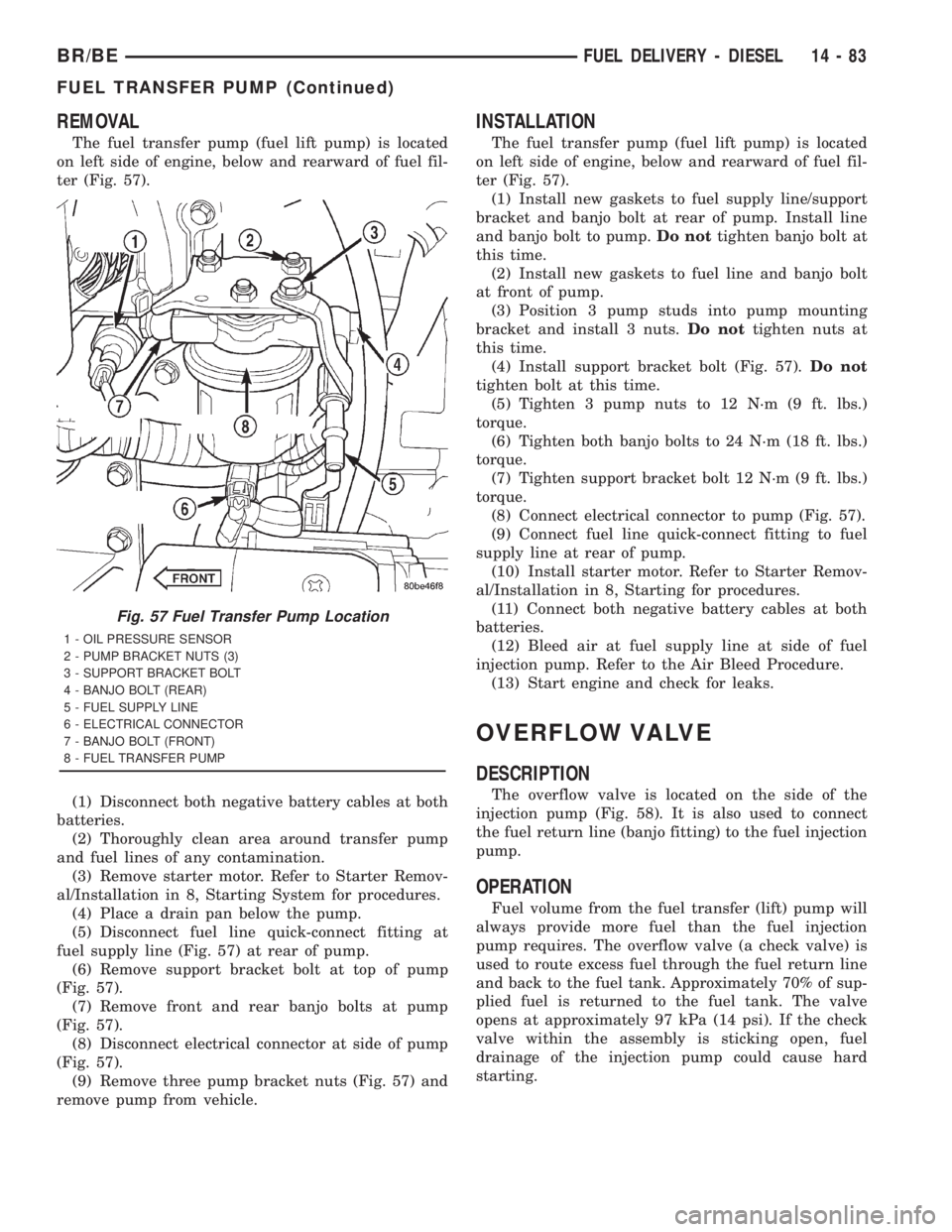
The fuel transfer pump (fuel lift pump) is located
on left side of engine, below and rearward of fuel fil-
ter (Fig. 57).
(1) Disconnect both negative battery cables at both
batteries.
(2) Thoroughly clean area around transfer pump
and fuel lines of any contamination.
(3) Remove starter motor. Refer to Starter Remov-
al/Installation in 8, Starting System for procedures.
(4) Place a drain pan below the pump.
(5) Disconnect fuel line quick-connect fitting at
fuel supply line (Fig. 57) at rear of pump.
(6) Remove support bracket bolt at top of pump
(Fig. 57).
(7) Remove front and rear banjo bolts at pump
(Fig. 57).
(8) Disconnect electrical connector at side of pump
(Fig. 57).
(9) Remove three pump bracket nuts (Fig. 57) and
remove pump from vehicle.
INSTALLATION
The fuel transfer pump (fuel lift pump) is located
on left side of engine, below and rearward of fuel fil-
ter (Fig. 57).
(1) Install new gaskets to fuel supply line/support
bracket and banjo bolt at rear of pump. Install line
and banjo bolt to pump.Do nottighten banjo bolt at
this time.
(2) Install new gaskets to fuel line and banjo bolt
at front of pump.
(3) Position 3 pump studs into pump mounting
bracket and install 3 nuts.Do nottighten nuts at
this time.
(4) Install support bracket bolt (Fig. 57).Do not
tighten bolt at this time.
(5) Tighten 3 pump nuts to 12 N´m (9 ft. lbs.)
torque.
(6) Tighten both banjo bolts to 24 N´m (18 ft. lbs.)
torque.
(7) Tighten support bracket bolt 12 N´m (9 ft. lbs.)
torque.
(8) Connect electrical connector to pump (Fig. 57).
(9) Connect fuel line quick-connect fitting to fuel
supply line at rear of pump.
(10) Install starter motor. Refer to Starter Remov-
al/Installation in 8, Starting for procedures.
(11) Connect both negative battery cables at both
batteries.
(12) Bleed air at fuel supply line at side of fuel
injection pump. Refer to the Air Bleed Procedure.
(13) Start engine and check for leaks.
OVERFLOW VALVE
DESCRIPTION
The overflow valve is located on the side of the
injection pump (Fig. 58). It is also used to connect
the fuel return line (banjo fitting) to the fuel injection
pump.
OPERATION
Fuel volume from the fuel transfer (lift) pump will
always provide more fuel than the fuel injection
pump requires. The overflow valve (a check valve) is
used to route excess fuel through the fuel return line
and back to the fuel tank. Approximately 70% of sup-
plied fuel is returned to the fuel tank. The valve
opens at approximately 97 kPa (14 psi). If the check
valve within the assembly is sticking open, fuel
drainage of the injection pump could cause hard
starting.
Fig. 57 Fuel Transfer Pump Location
1 - OIL PRESSURE SENSOR
2 - PUMP BRACKET NUTS (3)
3 - SUPPORT BRACKET BOLT
4 - BANJO BOLT (REAR)
5 - FUEL SUPPLY LINE
6 - ELECTRICAL CONNECTOR
7 - BANJO BOLT (FRONT)
8 - FUEL TRANSFER PUMP
BR/BEFUEL DELIVERY - DIESEL 14 - 83
FUEL TRANSFER PUMP (Continued)
Page 1572 of 2889
(1) Clean area around overflow valve and fuel
return line at injection pump before removal.
(2) Remove valve from pump and banjo fitting.
(3) Discard old sealing gaskets.
INSTALLATION
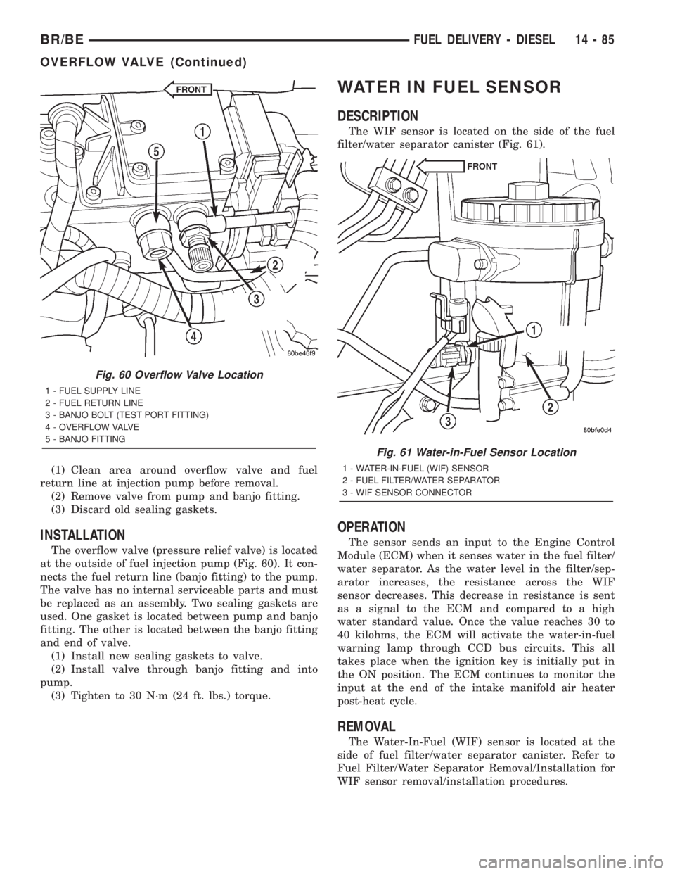
The overflow valve (pressure relief valve) is located
at the outside of fuel injection pump (Fig. 60). It con-
nects the fuel return line (banjo fitting) to the pump.
The valve has no internal serviceable parts and must
be replaced as an assembly. Two sealing gaskets are
used. One gasket is located between pump and banjo
fitting. The other is located between the banjo fitting
and end of valve.
(1) Install new sealing gaskets to valve.
(2) Install valve through banjo fitting and into
pump.
(3) Tighten to 30 N´m (24 ft. lbs.) torque.
WATER IN FUEL SENSOR
DESCRIPTION
The WIF sensor is located on the side of the fuel
filter/water separator canister (Fig. 61).
OPERATION
The sensor sends an input to the Engine Control
Module (ECM) when it senses water in the fuel filter/
water separator. As the water level in the filter/sep-
arator increases, the resistance across the WIF
sensor decreases. This decrease in resistance is sent
as a signal to the ECM and compared to a high
water standard value. Once the value reaches 30 to
40 kilohms, the ECM will activate the water-in-fuel
warning lamp through CCD bus circuits. This all
takes place when the ignition key is initially put in
the ON position. The ECM continues to monitor the
input at the end of the intake manifold air heater
post-heat cycle.
REMOVAL
The Water-In-Fuel (WIF) sensor is located at the
side of fuel filter/water separator canister. Refer to
Fuel Filter/Water Separator Removal/Installation for
WIF sensor removal/installation procedures.
Fig. 60 Overflow Valve Location
1 - FUEL SUPPLY LINE
2 - FUEL RETURN LINE
3 - BANJO BOLT (TEST PORT FITTING)
4 - OVERFLOW VALVE
5 - BANJO FITTING
Fig. 61 Water-in-Fuel Sensor Location
1 - WATER-IN-FUEL (WIF) SENSOR
2 - FUEL FILTER/WATER SEPARATOR
3 - WIF SENSOR CONNECTOR
BR/BEFUEL DELIVERY - DIESEL 14 - 85
OVERFLOW VALVE (Continued)
Page 1574 of 2889
FUEL INJECTION - DIESEL
TABLE OF CONTENTS
page page
FUEL INJECTION - DIESEL
DESCRIPTION...........................87
DIAGNOSIS AND TESTING.................89
BOOST PRESSURE.....................89
SPECIFICATIONS........................90
ACCELERATOR PEDAL POSITION SENSOR
DESCRIPTION...........................91
OPERATION.............................91
REMOVAL..............................91
INSTALLATION...........................93
FUEL INJECTOR
DESCRIPTION...........................93
OPERATION.............................94
DIAGNOSIS AND TESTING.................95
FUEL INJECTOR TEST...................95
REMOVAL..............................96
INSTALLATION...........................98
FUEL INJECTION PUMP RELAY
DESCRIPTION...........................99
OPERATION.............................99
FUEL TEMPERATURE SENSOR
DESCRIPTION...........................99
OPERATION............................100
INTAKE AIR HEATER
DESCRIPTION..........................100OPERATION............................100
REMOVAL.............................100
INSTALLATION..........................101
INTAKE AIR HEATER RELAY
DESCRIPTION..........................101
OPERATION............................102
REMOVAL.............................102
INSTALLATION..........................102
INTAKE AIR TEMPERATURE SENSOR
DESCRIPTION..........................102
OPERATION............................102
REMOVAL.............................103
INSTALLATION..........................103
MAP SENSOR
DESCRIPTION..........................103
OPERATION............................103
REMOVAL.............................104
INSTALLATION..........................104
PTO SWITCH
DESCRIPTION..........................104
THROTTLE CONTROL CABLE
REMOVAL.............................104
INSTALLATION..........................105
FUEL INJECTION - DIESEL
DESCRIPTION - DIESEL FUEL INJECTION
SYSTEM
The Engine Control Module (ECM) and Fuel Injec-
tion Pump Control Module (FPCM) are used prima-
rily for fuel system control. The ECM is a separate
replaceable component, while the FPCM is internal
to the fuel injection pump and is a non-serviceable
part. The ECM and FPCM are interconnected (wired
together) for fuel injection control.The Powertrain Control Module (PCM) is used to
regulate or control the A/C, charging and speed con-
trol systems. It is also used to partially control cer-
tain electronic automatic transmission components.
The PCM also has control over certain instrument
panel components.
Refer to either Powertrain Control Module (PCM)
or Engine Control Module (ECM) for additional infor-
mation. Refer to (Fig. 1) for a partial list of fuel sys-
tem components.
BR/BEFUEL INJECTION - DIESEL 14 - 87
Page 1575 of 2889
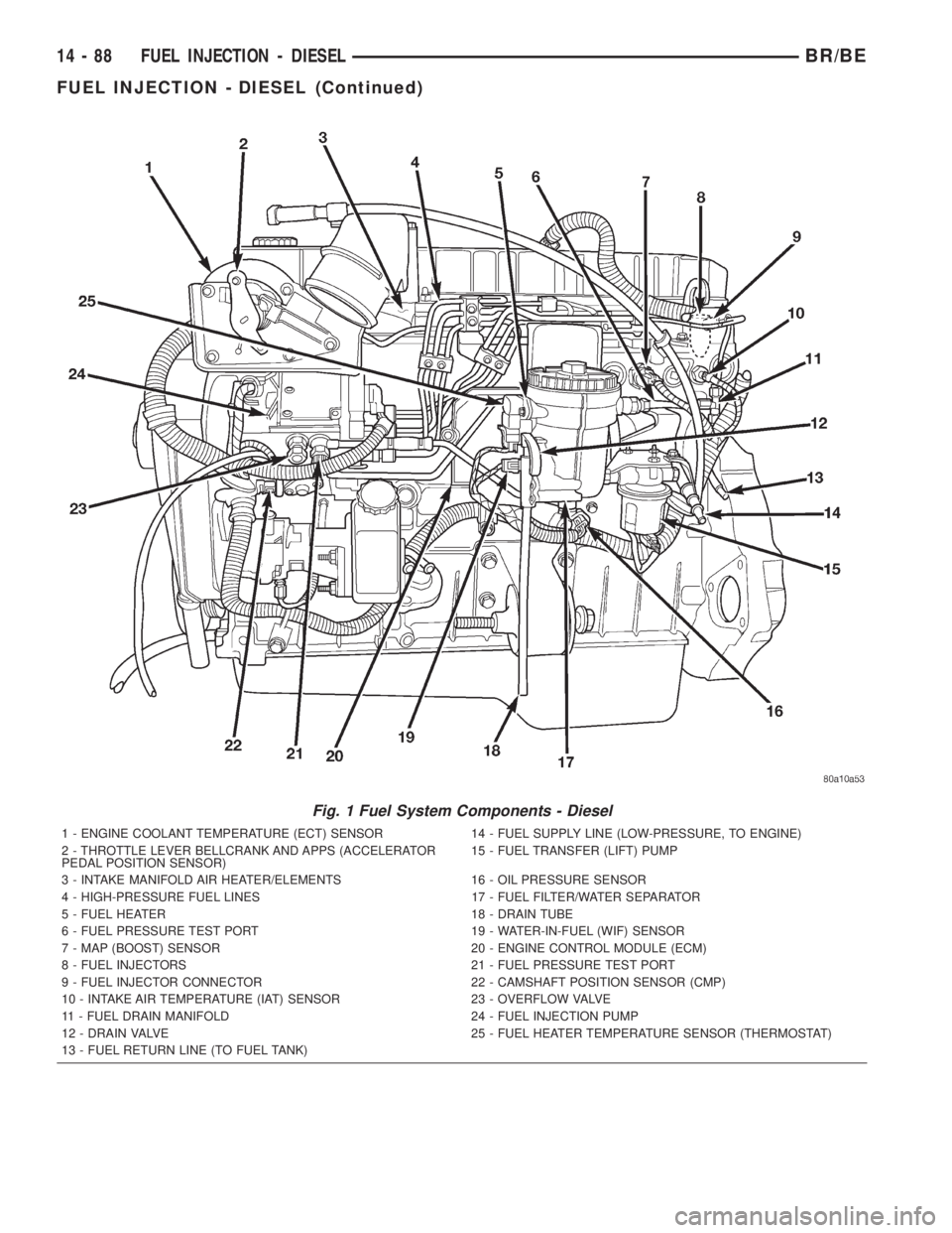
Fig. 1 Fuel System Components - Diesel
1 - ENGINE COOLANT TEMPERATURE (ECT) SENSOR 14 - FUEL SUPPLY LINE (LOW-PRESSURE, TO ENGINE)
2 - THROTTLE LEVER BELLCRANK AND APPS (ACCELERATOR
PEDAL POSITION SENSOR)15 - FUEL TRANSFER (LIFT) PUMP
3 - INTAKE MANIFOLD AIR HEATER/ELEMENTS 16 - OIL PRESSURE SENSOR
4 - HIGH-PRESSURE FUEL LINES 17 - FUEL FILTER/WATER SEPARATOR
5 - FUEL HEATER 18 - DRAIN TUBE
6 - FUEL PRESSURE TEST PORT 19 - WATER-IN-FUEL (WIF) SENSOR
7 - MAP (BOOST) SENSOR 20 - ENGINE CONTROL MODULE (ECM)
8 - FUEL INJECTORS 21 - FUEL PRESSURE TEST PORT
9 - FUEL INJECTOR CONNECTOR 22 - CAMSHAFT POSITION SENSOR (CMP)
10 - INTAKE AIR TEMPERATURE (IAT) SENSOR 23 - OVERFLOW VALVE
11 - FUEL DRAIN MANIFOLD 24 - FUEL INJECTION PUMP
12 - DRAIN VALVE 25 - FUEL HEATER TEMPERATURE SENSOR (THERMOSTAT)
13 - FUEL RETURN LINE (TO FUEL TANK)
14 - 88 FUEL INJECTION - DIESELBR/BE
FUEL INJECTION - DIESEL (Continued)
Page 1576 of 2889
DIAGNOSIS AND TESTING - BOOST PRESSURE
Two pressure gauges attached at two different
points are required for this test.(1) Obtain two 6828 fuel pressure test gauges
(equivalent gauges are OK).Gauge Consistency
Test:Connect the gauges together to a common pres-
sure source and verify pressure consistency of both
gauges. Do this consistency test at approximately 206
kPa (30 psi). If pressures are different, they can still
be used for test. Note and record differences in pres-
sures before testing. Make adjustments as necessary.
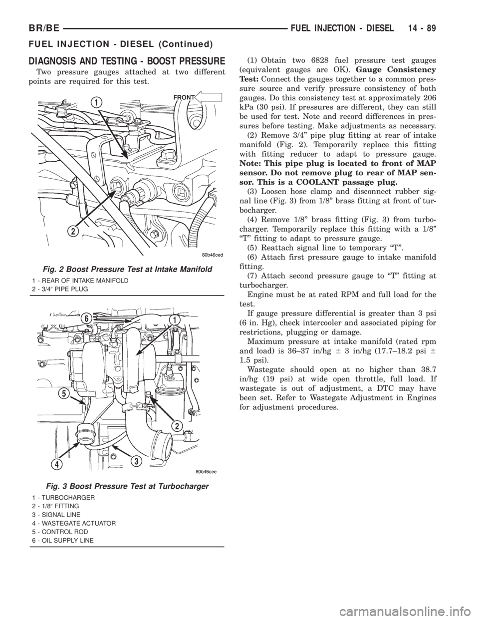
(2) Remove 3/4º pipe plug fitting at rear of intake
manifold (Fig. 2). Temporarily replace this fitting
with fitting reducer to adapt to pressure gauge.
Note: This pipe plug is located to front of MAP
sensor. Do not remove plug to rear of MAP sen-
sor. This is a COOLANT passage plug.
(3) Loosen hose clamp and disconnect rubber sig-
nal line (Fig. 3) from 1/8º brass fitting at front of tur-
bocharger.
(4) Remove 1/8º brass fitting (Fig. 3) from turbo-
charger. Temporarily replace this fitting with a 1/8º
ªTº fitting to adapt to pressure gauge.
(5) Reattach signal line to temporary ªTº.
(6) Attach first pressure gauge to intake manifold
fitting.
(7) Attach second pressure gauge to ªTº fitting at
turbocharger.
Engine must be at rated RPM and full load for the
test.
If gauge pressure differential is greater than 3 psi
(6 in. Hg), check intercooler and associated piping for
restrictions, plugging or damage.
Maximum pressure at intake manifold (rated rpm
and load) is 36±37 in/hg63 in/hg (17.7±18.2 psi6
1.5 psi).
Wastegate should open at no higher than 38.7
in/hg (19 psi) at wide open throttle, full load. If
wastegate is out of adjustment, a DTC may have
been set. Refer to Wastegate Adjustment in Engines
for adjustment procedures.
Fig. 2 Boost Pressure Test at Intake Manifold
1 - REAR OF INTAKE MANIFOLD
2 - 3/49PIPE PLUG
Fig. 3 Boost Pressure Test at Turbocharger
1 - TURBOCHARGER
2 - 1/89FITTING
3 - SIGNAL LINE
4 - WASTEGATE ACTUATOR
5 - CONTROL ROD
6 - OIL SUPPLY LINE
BR/BEFUEL INJECTION - DIESEL 14 - 89
FUEL INJECTION - DIESEL (Continued)
Page 1577 of 2889
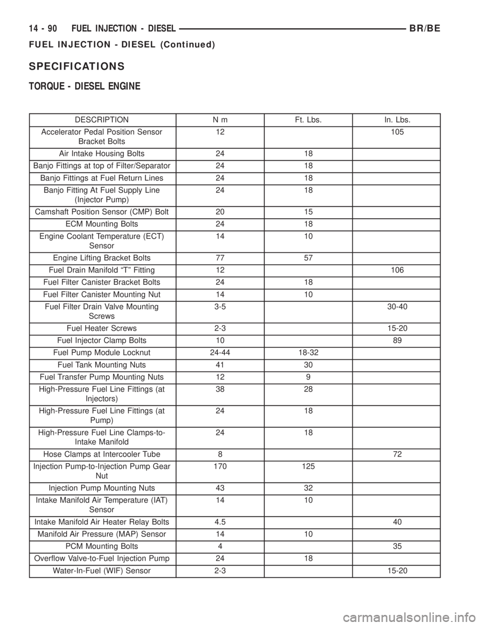
SPECIFICATIONS
TORQUE - DIESEL ENGINE
DESCRIPTION N m Ft. Lbs. In. Lbs.
Accelerator Pedal Position Sensor
Bracket Bolts12 105
Air Intake Housing Bolts 24 18
Banjo Fittings at top of Filter/Separator 24 18
Banjo Fittings at Fuel Return Lines 24 18
Banjo Fitting At Fuel Supply Line
(Injector Pump)24 18
Camshaft Position Sensor (CMP) Bolt 20 15
ECM Mounting Bolts 24 18
Engine Coolant Temperature (ECT)
Sensor14 10
Engine Lifting Bracket Bolts 77 57
Fuel Drain Manifold ªTº Fitting 12 106
Fuel Filter Canister Bracket Bolts 24 18
Fuel Filter Canister Mounting Nut 14 10
Fuel Filter Drain Valve Mounting
Screws3-5 30-40
Fuel Heater Screws 2-3 15-20
Fuel Injector Clamp Bolts 10 89
Fuel Pump Module Locknut 24-44 18-32
Fuel Tank Mounting Nuts 41 30
Fuel Transfer Pump Mounting Nuts 12 9
High-Pressure Fuel Line Fittings (at
Injectors)38 28
High-Pressure Fuel Line Fittings (at
Pump)24 18
High-Pressure Fuel Line Clamps-to-
Intake Manifold24 18
Hose Clamps at Intercooler Tube 8 72
Injection Pump-to-Injection Pump Gear
Nut170 125
Injection Pump Mounting Nuts 43 32
Intake Manifold Air Temperature (IAT)
Sensor14 10
Intake Manifold Air Heater Relay Bolts 4.5 40
Manifold Air Pressure (MAP) Sensor 14 10
PCM Mounting Bolts 4 35
Overflow Valve-to-Fuel Injection Pump 24 18
Water-In-Fuel (WIF) Sensor 2-3 15-20
14 - 90 FUEL INJECTION - DIESELBR/BE
FUEL INJECTION - DIESEL (Continued)
Page 1578 of 2889
ACCELERATOR PEDAL
POSITION SENSOR
DESCRIPTION
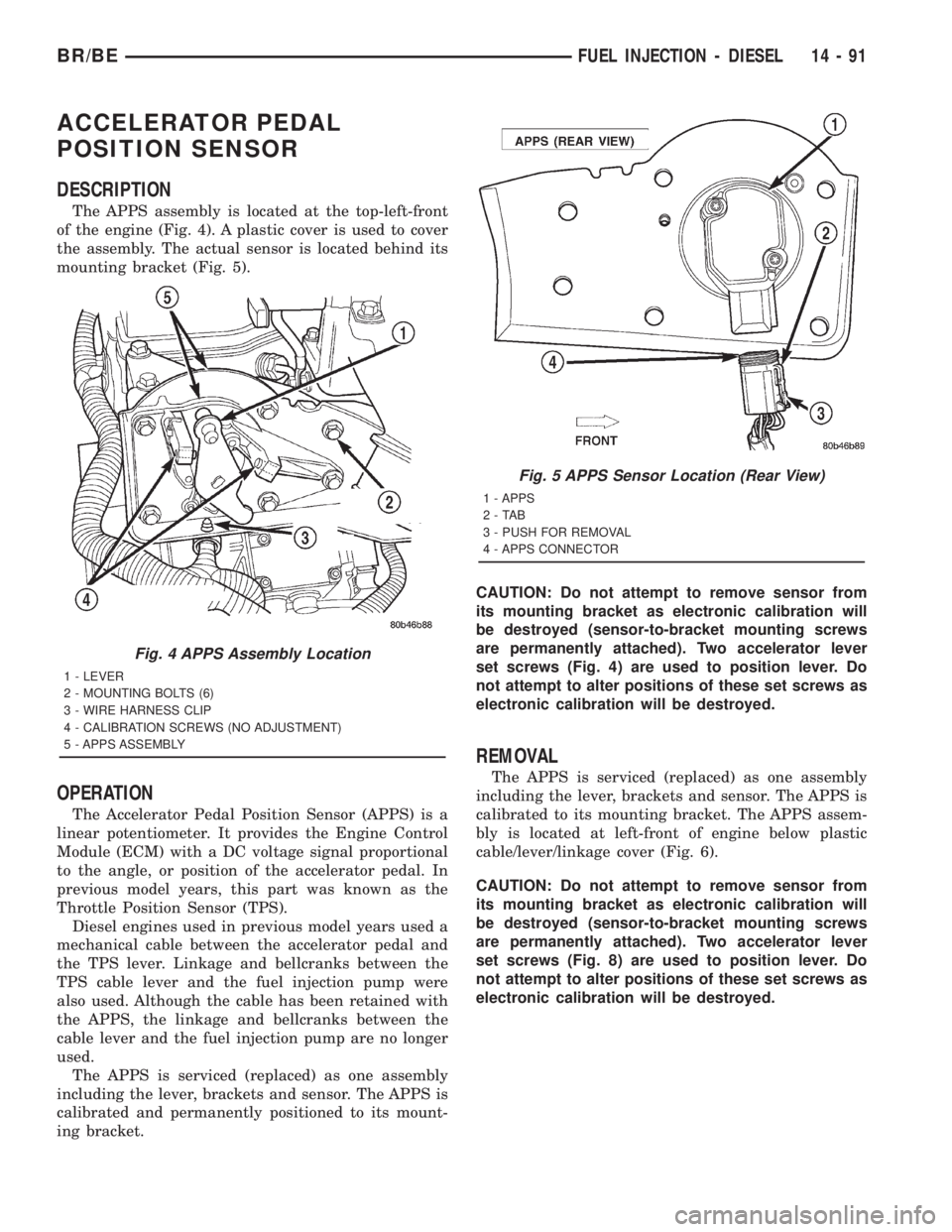
The APPS assembly is located at the top-left-front
of the engine (Fig. 4). A plastic cover is used to cover
the assembly. The actual sensor is located behind its
mounting bracket (Fig. 5).
OPERATION
The Accelerator Pedal Position Sensor (APPS) is a
linear potentiometer. It provides the Engine Control
Module (ECM) with a DC voltage signal proportional
to the angle, or position of the accelerator pedal. In
previous model years, this part was known as the
Throttle Position Sensor (TPS).
Diesel engines used in previous model years used a
mechanical cable between the accelerator pedal and
the TPS lever. Linkage and bellcranks between the
TPS cable lever and the fuel injection pump were
also used. Although the cable has been retained with
the APPS, the linkage and bellcranks between the
cable lever and the fuel injection pump are no longer
used.
The APPS is serviced (replaced) as one assembly
including the lever, brackets and sensor. The APPS is
calibrated and permanently positioned to its mount-
ing bracket.CAUTION: Do not attempt to remove sensor from
its mounting bracket as electronic calibration will
be destroyed (sensor-to-bracket mounting screws
are permanently attached). Two accelerator lever
set screws (Fig. 4) are used to position lever. Do
not attempt to alter positions of these set screws as
electronic calibration will be destroyed.
REMOVAL
The APPS is serviced (replaced) as one assembly
including the lever, brackets and sensor. The APPS is
calibrated to its mounting bracket. The APPS assem-
bly is located at left-front of engine below plastic
cable/lever/linkage cover (Fig. 6).
CAUTION: Do not attempt to remove sensor from
its mounting bracket as electronic calibration will
be destroyed (sensor-to-bracket mounting screws
are permanently attached). Two accelerator lever
set screws (Fig. 8) are used to position lever. Do
not attempt to alter positions of these set screws as
electronic calibration will be destroyed.
Fig. 4 APPS Assembly Location
1 - LEVER
2 - MOUNTING BOLTS (6)
3 - WIRE HARNESS CLIP
4 - CALIBRATION SCREWS (NO ADJUSTMENT)
5 - APPS ASSEMBLY
Fig. 5 APPS Sensor Location (Rear View)
1 - APPS
2-TAB
3 - PUSH FOR REMOVAL
4 - APPS CONNECTOR
BR/BEFUEL INJECTION - DIESEL 14 - 91