2001 DODGE RAM sensor
[x] Cancel search: sensorPage 1793 of 2889
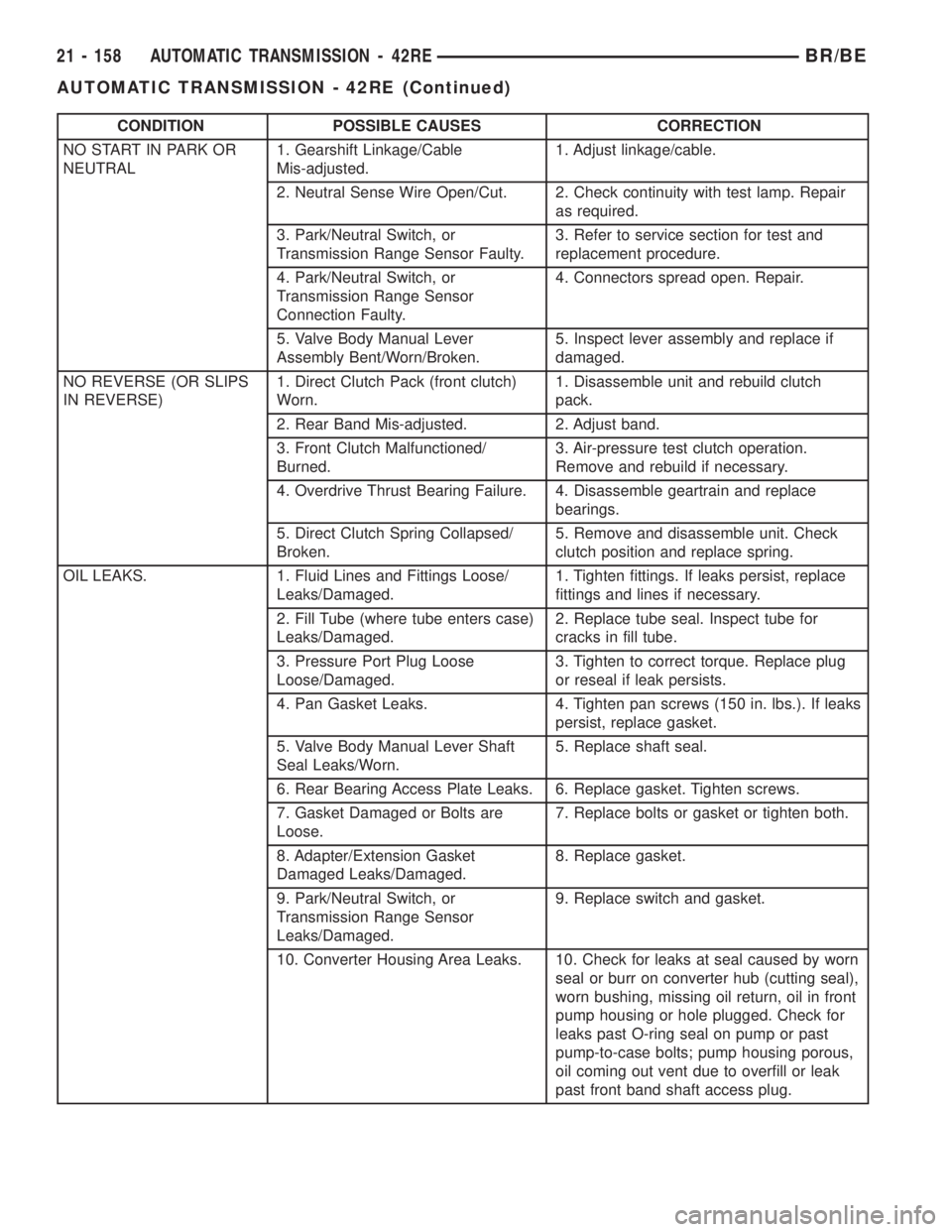
CONDITION POSSIBLE CAUSES CORRECTION
NO START IN PARK OR
NEUTRAL1. Gearshift Linkage/Cable
Mis-adjusted.1. Adjust linkage/cable.
2. Neutral Sense Wire Open/Cut. 2. Check continuity with test lamp. Repair
as required.
3. Park/Neutral Switch, or
Transmission Range Sensor Faulty.3. Refer to service section for test and
replacement procedure.
4. Park/Neutral Switch, or
Transmission Range Sensor
Connection Faulty.4. Connectors spread open. Repair.
5. Valve Body Manual Lever
Assembly Bent/Worn/Broken.5. Inspect lever assembly and replace if
damaged.
NO REVERSE (OR SLIPS
IN REVERSE)1. Direct Clutch Pack (front clutch)
Worn.1. Disassemble unit and rebuild clutch
pack.
2. Rear Band Mis-adjusted. 2. Adjust band.
3. Front Clutch Malfunctioned/
Burned.3. Air-pressure test clutch operation.
Remove and rebuild if necessary.
4. Overdrive Thrust Bearing Failure. 4. Disassemble geartrain and replace
bearings.
5. Direct Clutch Spring Collapsed/
Broken.5. Remove and disassemble unit. Check
clutch position and replace spring.
OIL LEAKS. 1. Fluid Lines and Fittings Loose/
Leaks/Damaged.1. Tighten fittings. If leaks persist, replace
fittings and lines if necessary.
2. Fill Tube (where tube enters case)
Leaks/Damaged.2. Replace tube seal. Inspect tube for
cracks in fill tube.
3. Pressure Port Plug Loose
Loose/Damaged.3. Tighten to correct torque. Replace plug
or reseal if leak persists.
4. Pan Gasket Leaks. 4. Tighten pan screws (150 in. lbs.). If leaks
persist, replace gasket.
5. Valve Body Manual Lever Shaft
Seal Leaks/Worn.5. Replace shaft seal.
6. Rear Bearing Access Plate Leaks. 6. Replace gasket. Tighten screws.
7. Gasket Damaged or Bolts are
Loose.7. Replace bolts or gasket or tighten both.
8. Adapter/Extension Gasket
Damaged Leaks/Damaged.8. Replace gasket.
9. Park/Neutral Switch, or
Transmission Range Sensor
Leaks/Damaged.9. Replace switch and gasket.
10. Converter Housing Area Leaks. 10. Check for leaks at seal caused by worn
seal or burr on converter hub (cutting seal),
worn bushing, missing oil return, oil in front
pump housing or hole plugged. Check for
leaks past O-ring seal on pump or past
pump-to-case bolts; pump housing porous,
oil coming out vent due to overfill or leak
past front band shaft access plug.
21 - 158 AUTOMATIC TRANSMISSION - 42REBR/BE
AUTOMATIC TRANSMISSION - 42RE (Continued)
Page 1794 of 2889
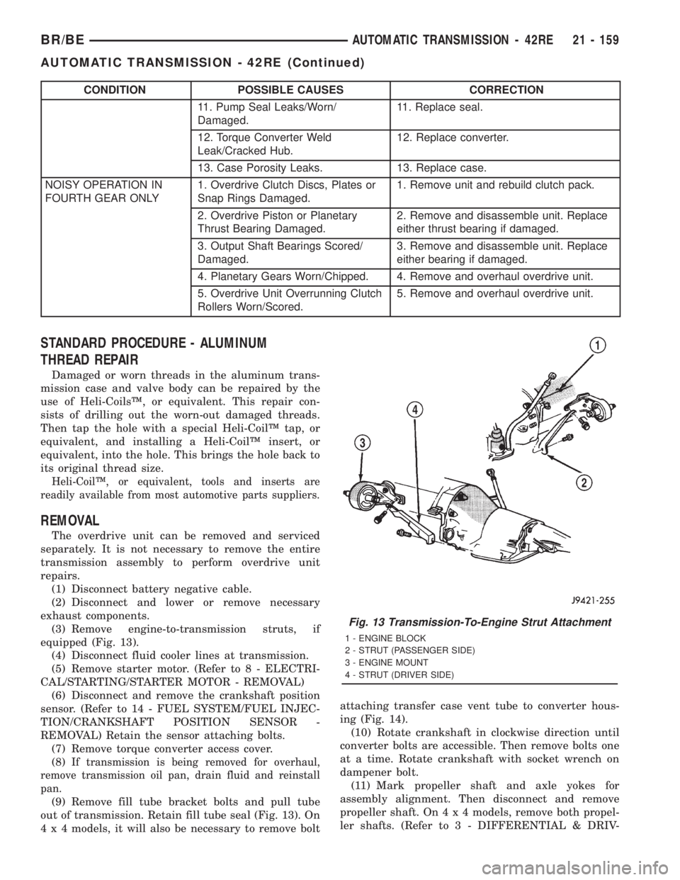
CONDITION POSSIBLE CAUSES CORRECTION
11. Pump Seal Leaks/Worn/
Damaged.11. Replace seal.
12. Torque Converter Weld
Leak/Cracked Hub.12. Replace converter.
13. Case Porosity Leaks. 13. Replace case.
NOISY OPERATION IN
FOURTH GEAR ONLY1. Overdrive Clutch Discs, Plates or
Snap Rings Damaged.1. Remove unit and rebuild clutch pack.
2. Overdrive Piston or Planetary
Thrust Bearing Damaged.2. Remove and disassemble unit. Replace
either thrust bearing if damaged.
3. Output Shaft Bearings Scored/
Damaged.3. Remove and disassemble unit. Replace
either bearing if damaged.
4. Planetary Gears Worn/Chipped. 4. Remove and overhaul overdrive unit.
5. Overdrive Unit Overrunning Clutch
Rollers Worn/Scored.5. Remove and overhaul overdrive unit.
STANDARD PROCEDURE - ALUMINUM
THREAD REPAIR
Damaged or worn threads in the aluminum trans-
mission case and valve body can be repaired by the
use of Heli-CoilsŸ, or equivalent. This repair con-
sists of drilling out the worn-out damaged threads.
Then tap the hole with a special Heli-CoilŸ tap, or
equivalent, and installing a Heli-CoilŸ insert, or
equivalent, into the hole. This brings the hole back to
its original thread size.
Heli-CoilŸ, or equivalent, tools and inserts are
readily available from most automotive parts suppliers.
REMOVAL
The overdrive unit can be removed and serviced
separately. It is not necessary to remove the entire
transmission assembly to perform overdrive unit
repairs.
(1) Disconnect battery negative cable.
(2) Disconnect and lower or remove necessary
exhaust components.
(3) Remove engine-to-transmission struts, if
equipped (Fig. 13).
(4) Disconnect fluid cooler lines at transmission.
(5) Remove starter motor. (Refer to 8 - ELECTRI-
CAL/STARTING/STARTER MOTOR - REMOVAL)
(6) Disconnect and remove the crankshaft position
sensor. (Refer to 14 - FUEL SYSTEM/FUEL INJEC-
TION/CRANKSHAFT POSITION SENSOR -
REMOVAL) Retain the sensor attaching bolts.
(7) Remove torque converter access cover.
(8)
If transmission is being removed for overhaul,
remove transmission oil pan, drain fluid and reinstall
pan.
(9) Remove fill tube bracket bolts and pull tube
out of transmission. Retain fill tube seal (Fig. 13). On
4 x 4 models, it will also be necessary to remove boltattaching transfer case vent tube to converter hous-
ing (Fig. 14).
(10) Rotate crankshaft in clockwise direction until
converter bolts are accessible. Then remove bolts one
at a time. Rotate crankshaft with socket wrench on
dampener bolt.
(11) Mark propeller shaft and axle yokes for
assembly alignment. Then disconnect and remove
propeller shaft. On4x4models, remove both propel-
ler shafts. (Refer to 3 - DIFFERENTIAL & DRIV-
Fig. 13 Transmission-To-Engine Strut Attachment
1 - ENGINE BLOCK
2 - STRUT (PASSENGER SIDE)
3 - ENGINE MOUNT
4 - STRUT (DRIVER SIDE)
BR/BEAUTOMATIC TRANSMISSION - 42RE 21 - 159
AUTOMATIC TRANSMISSION - 42RE (Continued)
Page 1796 of 2889
(4) Remove shift and throttle levers from valve
body manual lever shaft.
(5) Place transmission in horizontal position.
(6) Remove transmission oil pan and gasket.
(7)
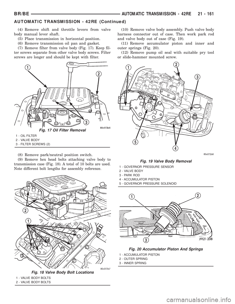
Remove filter from valve body (Fig. 17). Keep fil-
ter screws separate from other valve body screws. Filter
screws are longer and should be kept with filter.
(8) Remove park/neutral position switch.
(9)
Remove hex head bolts attaching valve body to
transmission case (Fig. 18). A total of 10 bolts are used.
Note different bolt lengths for assembly reference.
(10) Remove valve body assembly. Push valve body
harness connector out of case. Then work park rod
and valve body out of case (Fig. 19).
(11) Remove accumulator piston and inner and
outer springs (Fig. 20).
(12) Remove pump oil seal with suitable pry tool
or slide-hammer mounted screw.
Fig. 18 Valve Body Bolt Locations
1 - VALVE BODY BOLTS
2 - VALVE BODY BOLTS
Fig. 17 Oil Filter Removal
1 - OIL FILTER
2 - VALVE BODY
3 - FILTER SCREWS (2)
Fig. 19 Valve Body Removal
1 - GOVERNOR PRESSURE SENSOR
2 - VALVE BODY
3 - PARK ROD
4 - ACCUMULATOR PISTON
5 - GOVERNOR PRESSURE SOLENOID
Fig. 20 Accumulator Piston And Springs
1 - ACCUMULATOR PISTON
2 - OUTER SPRING
3 - INNER SPRING
BR/BEAUTOMATIC TRANSMISSION - 42RE 21 - 161
AUTOMATIC TRANSMISSION - 42RE (Continued)
Page 1807 of 2889
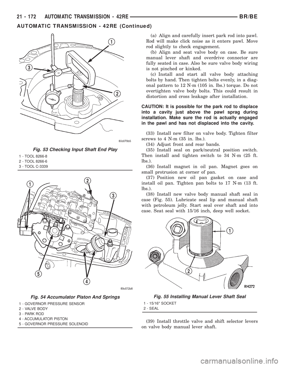
(a) Align and carefully insert park rod into pawl.
Rod will make click noise as it enters pawl. Move
rod slightly to check engagement.
(b) Align and seat valve body on case. Be sure
manual lever shaft and overdrive connector are
fully seated in case. Also be sure valve body wiring
is not pinched or kinked.
(c) Install and start all valve body attaching
bolts by hand. Then tighten bolts evenly, in a diag-
onal pattern to 12 N´m (105 in. lbs.) torque. Do not
overtighten valve body bolts. This could result in
distortion and cross leakage after installation.
CAUTION: It is possible for the park rod to displace
into a cavity just above the pawl sprag during
installation. Make sure the rod is actually engaged
in the pawl and has not displaced into the cavity.
(33) Install new filter on valve body. Tighten filter
screws to 4 N´m (35 in. lbs.).
(34) Adjust front and rear bands.
(35) Install seal on park/neutral position switch.
Then install and tighten switch to 34 N´m (25 ft.
lbs.).
(36) Install magnet in oil pan. Magnet goes on
small protrusion at corner of pan.
(37) Position new oil pan gasket on case and
install oil pan. Tighten pan bolts to 17 N´m (13 ft.
lbs.).
(38) Install new valve body manual shaft seal in
case (Fig. 55). Lubricate seal lip and manual shaft
with petroleum jelly. Start seal over shaft and into
case. Seat seal with 15/16 inch, deep well socket.
(39) Install throttle valve and shift selector levers
on valve body manual lever shaft.
Fig. 53 Checking Input Shaft End Play
1 - TOOL 8266-8
2 - TOOL 8266-6
3 - TOOL C-3339
Fig. 54 Accumulator Piston And Springs
1 - GOVERNOR PRESSURE SENSOR
2 - VALVE BODY
3 - PARK ROD
4 - ACCUMULATOR PISTON
5 - GOVERNOR PRESSURE SOLENOID
Fig. 55 Installing Manual Lever Shaft Seal
1 - 15/16©© SOCKET
2 - SEAL
21 - 172 AUTOMATIC TRANSMISSION - 42REBR/BE
AUTOMATIC TRANSMISSION - 42RE (Continued)
Page 1808 of 2889
INSTALLATION
(1) Check torque converter hub and hub drive
notches for sharp edges burrs, scratches, or nicks.
Polish the hub and notches with 320/400 grit paper
and crocus cloth if necessary. The hub must be
smooth to avoid damaging pump seal at installation.
(2) Lubricate pocket in the rear oil pump seal lip
with transmission fluid.
(3) Lubricate converter pilot hub of the crankshaft
with a light coating of MopartHigh Temp Grease.
(4) Align and install converter in oil pump.
(5) Carefully insert converter in oil pump. Then
rotate converter back and forth until fully seated in
pump gears.
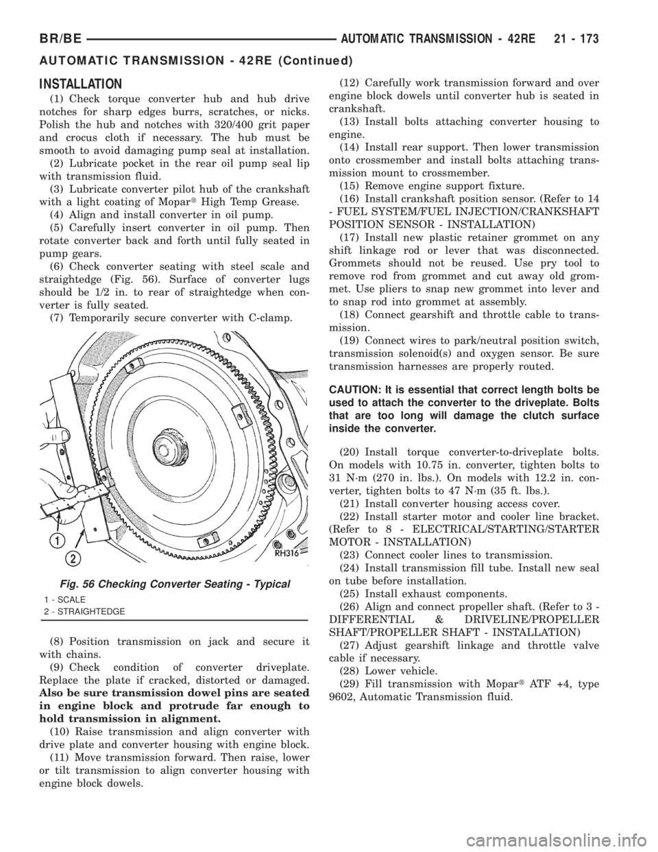
(6) Check converter seating with steel scale and
straightedge (Fig. 56). Surface of converter lugs
should be 1/2 in. to rear of straightedge when con-
verter is fully seated.
(7) Temporarily secure converter with C-clamp.
(8) Position transmission on jack and secure it
with chains.
(9) Check condition of converter driveplate.
Replace the plate if cracked, distorted or damaged.
Also be sure transmission dowel pins are seated
in engine block and protrude far enough to
hold transmission in alignment.
(10) Raise transmission and align converter with
drive plate and converter housing with engine block.
(11) Move transmission forward. Then raise, lower
or tilt transmission to align converter housing with
engine block dowels.(12) Carefully work transmission forward and over
engine block dowels until converter hub is seated in
crankshaft.
(13) Install bolts attaching converter housing to
engine.
(14) Install rear support. Then lower transmission
onto crossmember and install bolts attaching trans-
mission mount to crossmember.
(15) Remove engine support fixture.
(16) Install crankshaft position sensor. (Refer to 14
- FUEL SYSTEM/FUEL INJECTION/CRANKSHAFT
POSITION SENSOR - INSTALLATION)
(17) Install new plastic retainer grommet on any
shift linkage rod or lever that was disconnected.
Grommets should not be reused. Use pry tool to
remove rod from grommet and cut away old grom-
met. Use pliers to snap new grommet into lever and
to snap rod into grommet at assembly.
(18) Connect gearshift and throttle cable to trans-
mission.
(19) Connect wires to park/neutral position switch,
transmission solenoid(s) and oxygen sensor. Be sure
transmission harnesses are properly routed.
CAUTION: It is essential that correct length bolts be
used to attach the converter to the driveplate. Bolts
that are too long will damage the clutch surface
inside the converter.
(20) Install torque converter-to-driveplate bolts.
On models with 10.75 in. converter, tighten bolts to
31 N´m (270 in. lbs.). On models with 12.2 in. con-
verter, tighten bolts to 47 N´m (35 ft. lbs.).
(21) Install converter housing access cover.
(22) Install starter motor and cooler line bracket.
(Refer to 8 - ELECTRICAL/STARTING/STARTER
MOTOR - INSTALLATION)
(23) Connect cooler lines to transmission.
(24) Install transmission fill tube. Install new seal
on tube before installation.
(25) Install exhaust components.
(26) Align and connect propeller shaft. (Refer to 3 -
DIFFERENTIAL & DRIVELINE/PROPELLER
SHAFT/PROPELLER SHAFT - INSTALLATION)
(27) Adjust gearshift linkage and throttle valve
cable if necessary.
(28) Lower vehicle.
(29) Fill transmission with MopartATF +4, type
9602, Automatic Transmission fluid.
Fig. 56 Checking Converter Seating - Typical
1 - SCALE
2 - STRAIGHTEDGE
BR/BEAUTOMATIC TRANSMISSION - 42RE 21 - 173
AUTOMATIC TRANSMISSION - 42RE (Continued)
Page 1822 of 2889
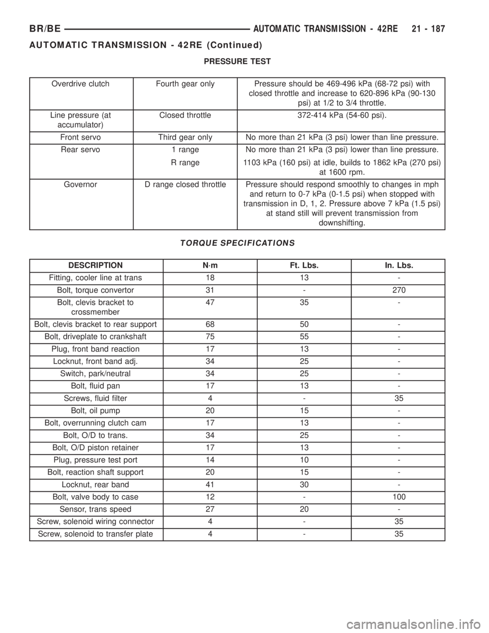
PRESSURE TEST
Overdrive clutch Fourth gear only Pressure should be 469-496 kPa (68-72 psi) with
closed throttle and increase to 620-896 kPa (90-130
psi) at 1/2 to 3/4 throttle.
Line pressure (at
accumulator)Closed throttle 372-414 kPa (54-60 psi).
Front servo Third gear only No more than 21 kPa (3 psi) lower than line pressure.
Rear servo 1 range No more than 21 kPa (3 psi) lower than line pressure.
R range 1103 kPa (160 psi) at idle, builds to 1862 kPa (270 psi)
at 1600 rpm.
Governor D range closed throttle Pressure should respond smoothly to changes in mph
and return to 0-7 kPa (0-1.5 psi) when stopped with
transmission in D, 1, 2. Pressure above 7 kPa (1.5 psi)
at stand still will prevent transmission from
downshifting.
TORQUE SPECIFICATIONS
DESCRIPTION N´m Ft. Lbs. In. Lbs.
Fitting, cooler line at trans 18 13 -
Bolt, torque convertor 31 - 270
Bolt, clevis bracket to
crossmember47 35 -
Bolt, clevis bracket to rear support 68 50 -
Bolt, driveplate to crankshaft 75 55 -
Plug, front band reaction 17 13 -
Locknut, front band adj. 34 25 -
Switch, park/neutral 34 25 -
Bolt, fluid pan 17 13 -
Screws, fluid filter 4 - 35
Bolt, oil pump 20 15 -
Bolt, overrunning clutch cam 17 13 -
Bolt, O/D to trans. 34 25 -
Bolt, O/D piston retainer 17 13 -
Plug, pressure test port 14 10 -
Bolt, reaction shaft support 20 15 -
Locknut, rear band 41 30 -
Bolt, valve body to case 12 - 100
Sensor, trans speed 27 20 -
Screw, solenoid wiring connector 4 - 35
Screw, solenoid to transfer plate 4 - 35
BR/BEAUTOMATIC TRANSMISSION - 42RE 21 - 187
AUTOMATIC TRANSMISSION - 42RE (Continued)
Page 1829 of 2889
(7) Position new gasket on oil pan and install pan
on transmission. Tighten pan bolts to 17 N´m (13 ft.
lbs.) torque.
(8) Lower vehicle and refill transmission with
MopartATF +4, type 9602, fluid.
ELECTRONIC GOVERNOR
DESCRIPTION
Governor pressure is controlled electronically. Com-
ponents used for governor pressure control include:
²Governor body
²Valve body transfer plate
²Governor pressure solenoid valve
²Governor pressure sensor
²Fluid temperature thermistor
²Throttle position sensor (TPS)
²Transmission speed sensor
²Powertrain control module (PCM)
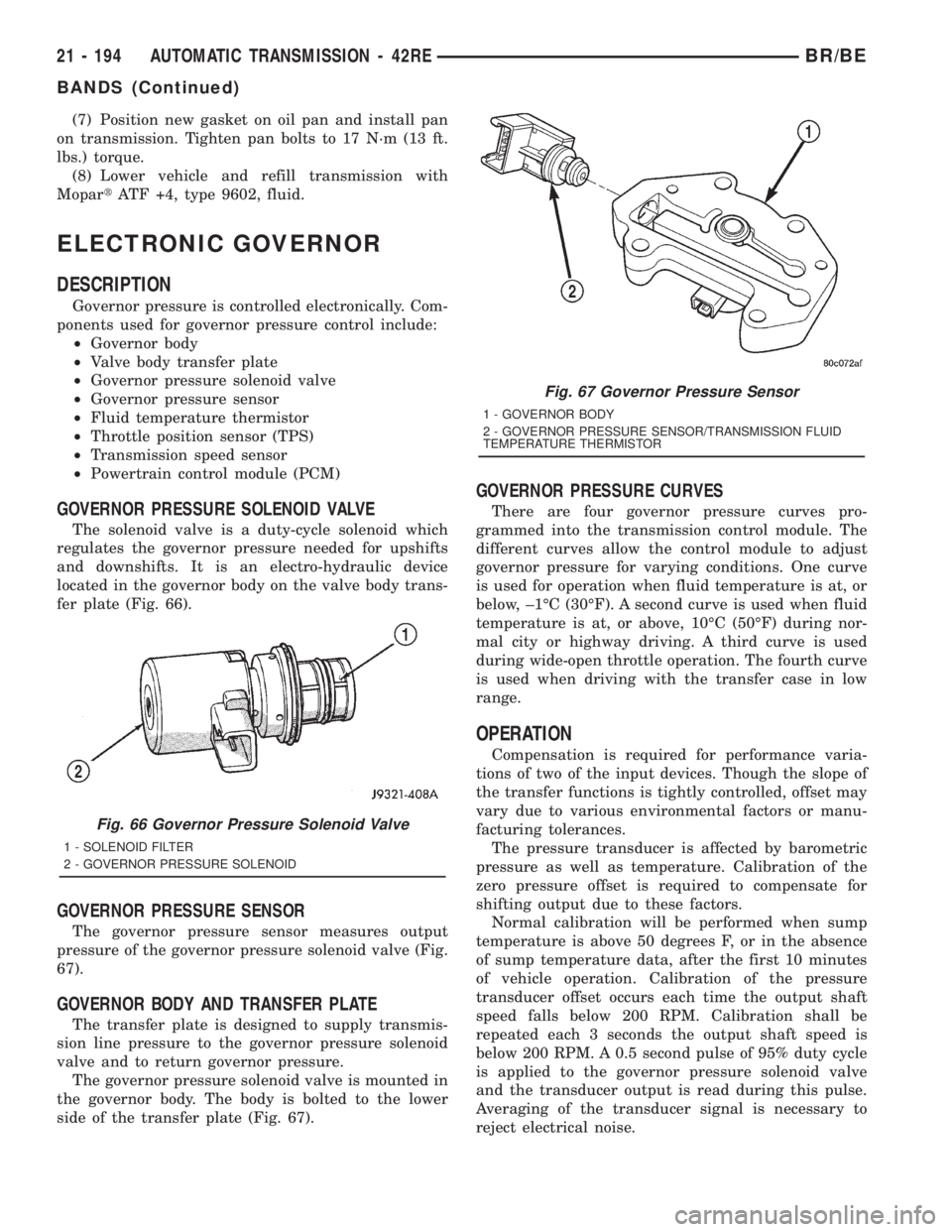
GOVERNOR PRESSURE SOLENOID VALVE
The solenoid valve is a duty-cycle solenoid which
regulates the governor pressure needed for upshifts
and downshifts. It is an electro-hydraulic device
located in the governor body on the valve body trans-
fer plate (Fig. 66).
GOVERNOR PRESSURE SENSOR
The governor pressure sensor measures output
pressure of the governor pressure solenoid valve (Fig.
67).
GOVERNOR BODY AND TRANSFER PLATE
The transfer plate is designed to supply transmis-
sion line pressure to the governor pressure solenoid
valve and to return governor pressure.
The governor pressure solenoid valve is mounted in
the governor body. The body is bolted to the lower
side of the transfer plate (Fig. 67).
GOVERNOR PRESSURE CURVES
There are four governor pressure curves pro-
grammed into the transmission control module. The
different curves allow the control module to adjust
governor pressure for varying conditions. One curve
is used for operation when fluid temperature is at, or
below, ±1ÉC (30ÉF). A second curve is used when fluid
temperature is at, or above, 10ÉC (50ÉF) during nor-
mal city or highway driving. A third curve is used
during wide-open throttle operation. The fourth curve
is used when driving with the transfer case in low
range.
OPERATION
Compensation is required for performance varia-
tions of two of the input devices. Though the slope of
the transfer functions is tightly controlled, offset may
vary due to various environmental factors or manu-
facturing tolerances.
The pressure transducer is affected by barometric
pressure as well as temperature. Calibration of the
zero pressure offset is required to compensate for
shifting output due to these factors.
Normal calibration will be performed when sump
temperature is above 50 degrees F, or in the absence
of sump temperature data, after the first 10 minutes
of vehicle operation. Calibration of the pressure
transducer offset occurs each time the output shaft
speed falls below 200 RPM. Calibration shall be
repeated each 3 seconds the output shaft speed is
below 200 RPM. A 0.5 second pulse of 95% duty cycle
is applied to the governor pressure solenoid valve
and the transducer output is read during this pulse.
Averaging of the transducer signal is necessary to
reject electrical noise.
Fig. 66 Governor Pressure Solenoid Valve
1 - SOLENOID FILTER
2 - GOVERNOR PRESSURE SOLENOID
Fig. 67 Governor Pressure Sensor
1 - GOVERNOR BODY
2 - GOVERNOR PRESSURE SENSOR/TRANSMISSION FLUID
TEMPERATURE THERMISTOR
21 - 194 AUTOMATIC TRANSMISSION - 42REBR/BE
BANDS (Continued)
Page 1830 of 2889
Under cold conditions (below 50 degrees F sump),
the governor pressure solenoid valve response may
be too slow to guarantee 0 psi during the 0.5 second
calibration pulse. Calibration pulses are continued
during this period, however the transducer output
valves are discarded. Transducer offset must be read
at key-on, under conditions which promote a stable
reading. This value is retained and becomes the off-
set during the9cold9period of operation.
GOVERNOR PRESSURE SOLENOID VALVE
The inlet side of the solenoid valve is exposed to
normal transmission line pressure. The outlet side of
the valve leads to the valve body governor circuit.
The solenoid valve regulates line pressure to pro-
duce governor pressure. The average current sup-
plied to the solenoid controls governor pressure. One
amp current produces zero kPa/psi governor pres-
sure. Zero amps sets the maximum governor pres-
sure.
The powertrain control module (PCM) turns on the
trans control relay which supplies electrical power to
the solenoid valve. Operating voltage is 12 volts
(DC). The PCM controls the ground side of the sole-
noid using the governor pressure solenoid control cir-
cuit.
GOVERNOR PRESSURE SENSOR
The sensor output signal provides the necessary
feedback to the PCM. This feedback is needed to ade-
quately control governor pressure.
GOVERNOR BODY AND TRANSFER PLATE
The transfer plate channels line pressure to the
solenoid valve through the governor body. It also
channels governor pressure from the solenoid valve
to the governor circuit. It is the solenoid valve that
develops the necessary governor pressure.
GOVERNOR PRESSURE CURVES
LOW TRANSMISSION FLUID TEMPERATURE
When the transmission fluid is cold the conven-
tional governor can delay shifts, resulting in higher
than normal shift speeds and harsh shifts. The elec-
tronically controlled low temperature governor pres-
sure curve is higher than normal to make the
transmission shift at normal speeds and sooner. The
PCM uses a temperature sensor in the transmission
oil sump to determine when low temperature gover-
nor pressure is needed.NORMAL OPERATION
Normal operation is refined through the increased
computing power of the PCM and through access to
data on engine operating conditions provided by the
PCM that were not available with the previous
stand-alone electronic module. This facilitated the
development of a load adaptive shift strategy - the
ability to alter the shift schedule in response to vehi-
cle load condition. One manifestation of this capabil-
ity is grade9hunting9prevention - the ability of the
transmission logic to delay an upshift on a grade if
the engine does not have sufficient power to main-
tain speed in the higher gear. The 3-2 downshift and
the potential for hunting between gears occurs with a
heavily loaded vehicle or on steep grades. When
hunting occurs, it is very objectionable because shifts
are frequent and accompanied by large changes in
noise and acceleration.
WIDE OPEN THROTTLE OPERATION
In wide-open throttle (WOT) mode, adaptive mem-
ory in the PCM assures that up-shifts occur at the
preprogrammed optimum speed. WOT operation is
determined from the throttle position sensor, which
is also a part of the emission control system. The ini-
tial setting for the WOT upshift is below the opti-
mum engine speed. As WOT shifts are repeated, the
PCM learns the time required to complete the shifts
by comparing the engine speed when the shifts occur
to the optimum speed. After each shift, the PCM
adjusts the shift point until the optimum speed is
reached. The PCM also considers vehicle loading,
grade and engine performance changes due to high
altitude in determining when to make WOT shifts. It
does this by measuring vehicle and engine accelera-
tion and then factoring in the shift time.
TRANSFER CASE LOW RANGE OPERATION
On four-wheel drive vehicles operating in low
range, the engine can accelerate to its peak more
rapidly than in Normal range, resulting in delayed
shifts and undesirable engine9flare.9The low range
governor pressure curve is also higher than normal
to initiate upshifts sooner. The PCM compares elec-
tronic vehicle speed signal used by the speedometer
to the transmission output shaft speed signal to
determine when the transfer case is in low range.
BR/BEAUTOMATIC TRANSMISSION - 42RE 21 - 195
ELECTRONIC GOVERNOR (Continued)