2001 DODGE RAM sensor
[x] Cancel search: sensorPage 1579 of 2889
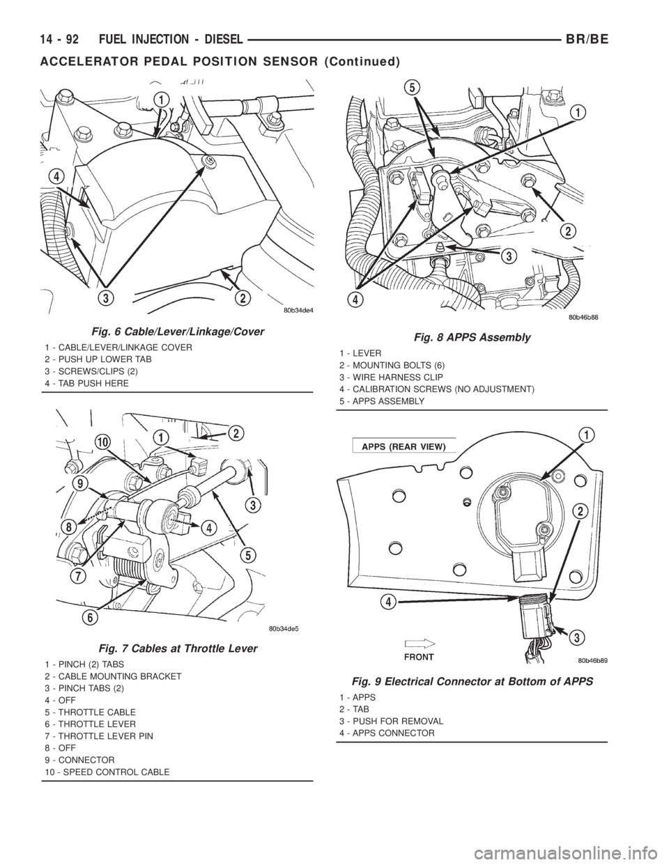
Fig. 6 Cable/Lever/Linkage/Cover
1 - CABLE/LEVER/LINKAGE COVER
2 - PUSH UP LOWER TAB
3 - SCREWS/CLIPS (2)
4 - TAB PUSH HERE
Fig. 7 Cables at Throttle Lever
1 - PINCH (2) TABS
2 - CABLE MOUNTING BRACKET
3 - PINCH TABS (2)
4 - OFF
5 - THROTTLE CABLE
6 - THROTTLE LEVER
7 - THROTTLE LEVER PIN
8 - OFF
9 - CONNECTOR
10 - SPEED CONTROL CABLE
Fig. 8 APPS Assembly
1 - LEVER
2 - MOUNTING BOLTS (6)
3 - WIRE HARNESS CLIP
4 - CALIBRATION SCREWS (NO ADJUSTMENT)
5 - APPS ASSEMBLY
Fig. 9 Electrical Connector at Bottom of APPS
1 - APPS
2-TAB
3 - PUSH FOR REMOVAL
4 - APPS CONNECTOR
14 - 92 FUEL INJECTION - DIESELBR/BE
ACCELERATOR PEDAL POSITION SENSOR (Continued)
Page 1580 of 2889
(1) Disconnect both negative battery cables at both
batteries.
(2) Remove cable cover (Fig. 6). Cable cover is
attached with 2 Phillips screws, 2 plastic retention
clips and 2 push tabs (Fig. 6). Remove 2 Phillips
screws and carefully pry out 2 retention clips. After
clip removal, push rearward on front tab, and
upward on lower tab for cover removal.
(3) Using finger pressure only, disconnect end of
speed control servo cable from throttle lever pin by
pulling forward on connector while holding lever
rearward (Fig. 7).DO NOT try to pull connector
off perpendicular to lever pin. Connector will
be broken.
(4) Using two small screwdrivers, pry throttle
cable connector socket from throttle lever ball (Fig.
7).Be very careful not to bend throttle lever
arm.
(5) Disconnect transmission control cable at lever
arm (if equipped). Refer to 21, Transmission.
(6) Squeeze pinch tabs on speed control cable (Fig.
7) and pull cable rearward to remove from cable
mounting bracket.
(7) Squeeze pinch tabs on throttle cable (Fig. 7)
and pull cable rearward to remove from cable mount-
ing bracket.
(8) If equipped with an automatic transmission,
refer to 21, Transmission for transmission control
cable removal procedures.
(9) Disconnect wiring harness clip (Fig. 8) at bot-
tom of bracket.
(10) Remove 6 mounting bolts (Fig. 8) and par-
tially remove APPS assembly from engine. After
assembly is partially removed, disconnect electrical
connector from bottom of sensor by pushing on con-
nector tab (Fig. 9).
(11) Remove APPS assembly from engine.
INSTALLATION
The APPS is serviced (replaced) as one assembly
including the lever, brackets and sensor. The APPS is
calibrated to its mounting bracket. The APPS assem-
bly is located at left-front of engine below plastic
cable/lever/linkage cover (Fig. 6).
(1) Snap electrical connector into bottom of sensor.
(2) Position APPS assembly to engine and install 6
bolts. Tighten bolts to 12 N´m (105 in. lbs.) torque.
(3) Connect wiring harness clip (Fig. 8) at bottom
of bracket.
(4) If equipped with an automatic transmission,
refer to Group 21, Transmission for transmission con-
trol cable installation procedures.
(5) Install speed control cable into mounting
bracket. Be sure pinch tabs (Fig. 7) have secured
cable.(6) Install throttle cable into mounting bracket. Be
sure pinch tabs (Fig. 7) have secured cable.
(7) Connect throttle cable at lever (snaps on).
(8) Connect speed control cable to lever by pushing
cable connector rearward onto lever pin while hold-
ing lever forward.
(9) Install cable cover.
(10) Connect both negative battery cables to both
batteries.
(11)ECM Calibration:Turn key to ON position.
Without starting engine, slowly press throttle pedal
to floor and then slowly release. This step must be
done (one time) to ensure accelerator pedal position
sensor calibration has been learned by ECM. If not
done, possible DTC's may be set.
(12) Use DRB scan tool to erase any DTC's from
ECM/PCM.
FUEL INJECTOR
DESCRIPTION
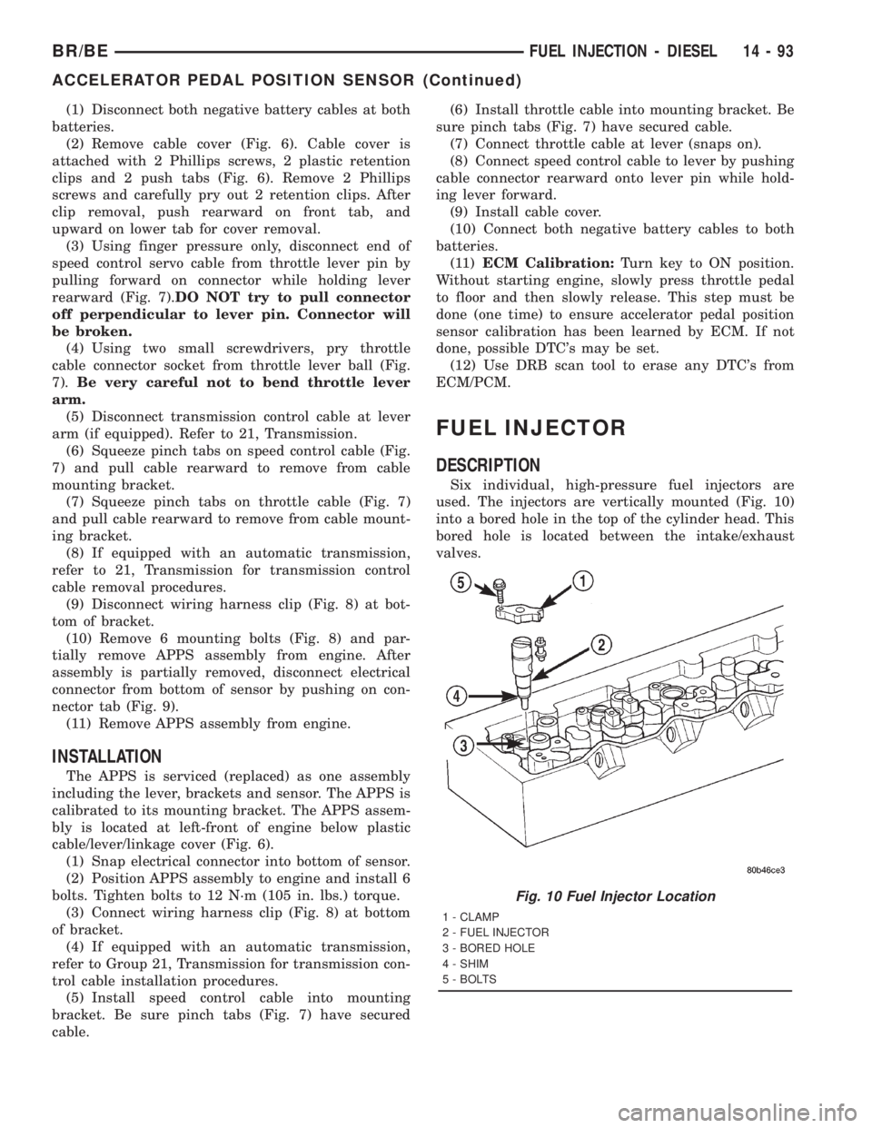
Six individual, high-pressure fuel injectors are
used. The injectors are vertically mounted (Fig. 10)
into a bored hole in the top of the cylinder head. This
bored hole is located between the intake/exhaust
valves.
Fig. 10 Fuel Injector Location
1 - CLAMP
2 - FUEL INJECTOR
3 - BORED HOLE
4 - SHIM
5 - BOLTS
BR/BEFUEL INJECTION - DIESEL 14 - 93
ACCELERATOR PEDAL POSITION SENSOR (Continued)
Page 1586 of 2889
(g) If any of these conditions occur, replace injec-
tor.
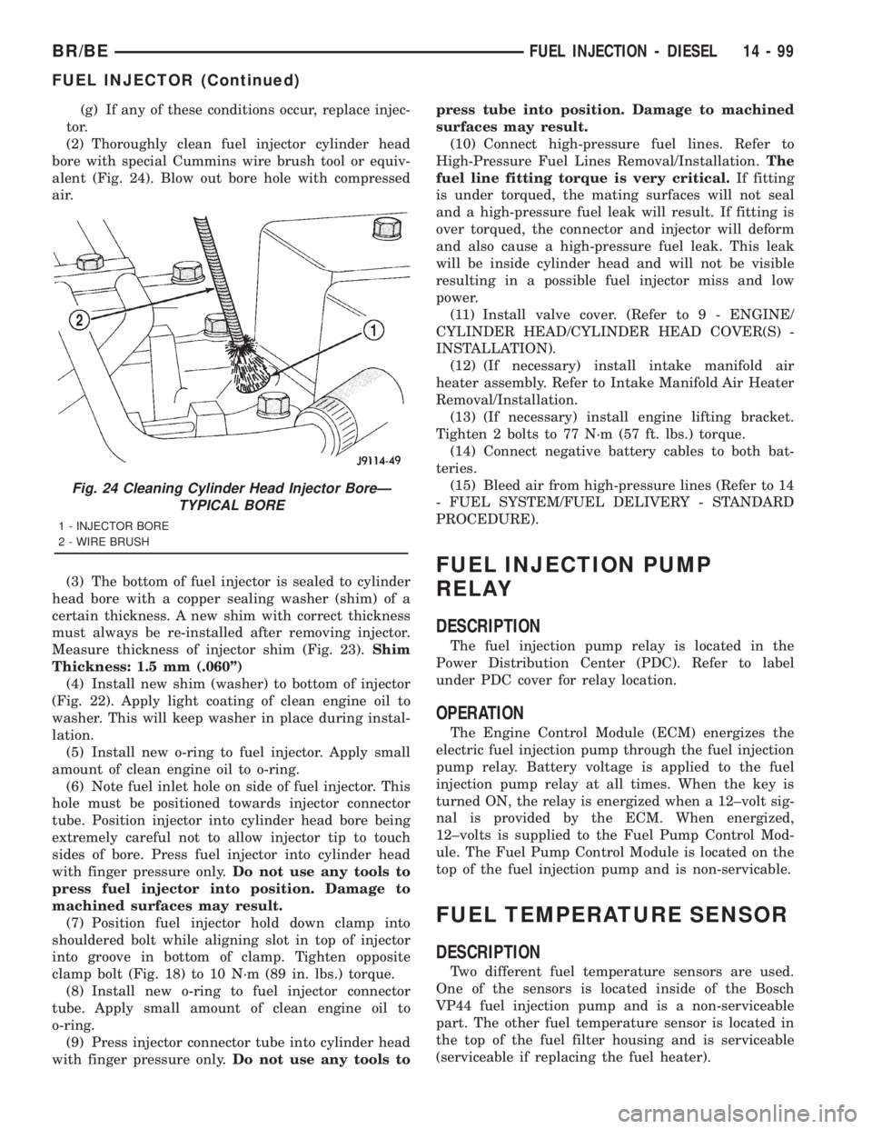
(2) Thoroughly clean fuel injector cylinder head
bore with special Cummins wire brush tool or equiv-
alent (Fig. 24). Blow out bore hole with compressed
air.
(3) The bottom of fuel injector is sealed to cylinder
head bore with a copper sealing washer (shim) of a
certain thickness. A new shim with correct thickness
must always be re-installed after removing injector.
Measure thickness of injector shim (Fig. 23).Shim
Thickness: 1.5 mm (.060º)
(4) Install new shim (washer) to bottom of injector
(Fig. 22). Apply light coating of clean engine oil to
washer. This will keep washer in place during instal-
lation.
(5) Install new o-ring to fuel injector. Apply small
amount of clean engine oil to o-ring.
(6) Note fuel inlet hole on side of fuel injector. This
hole must be positioned towards injector connector
tube. Position injector into cylinder head bore being
extremely careful not to allow injector tip to touch
sides of bore. Press fuel injector into cylinder head
with finger pressure only.Do not use any tools to
press fuel injector into position. Damage to
machined surfaces may result.
(7) Position fuel injector hold down clamp into
shouldered bolt while aligning slot in top of injector
into groove in bottom of clamp. Tighten opposite
clamp bolt (Fig. 18) to 10 N´m (89 in. lbs.) torque.
(8) Install new o-ring to fuel injector connector
tube. Apply small amount of clean engine oil to
o-ring.
(9) Press injector connector tube into cylinder head
with finger pressure only.Do not use any tools topress tube into position. Damage to machined
surfaces may result.
(10) Connect high-pressure fuel lines. Refer to
High-Pressure Fuel Lines Removal/Installation.The
fuel line fitting torque is very critical.If fitting
is under torqued, the mating surfaces will not seal
and a high-pressure fuel leak will result. If fitting is
over torqued, the connector and injector will deform
and also cause a high-pressure fuel leak. This leak
will be inside cylinder head and will not be visible
resulting in a possible fuel injector miss and low
power.
(11) Install valve cover. (Refer to 9 - ENGINE/
CYLINDER HEAD/CYLINDER HEAD COVER(S) -
INSTALLATION).
(12) (If necessary) install intake manifold air
heater assembly. Refer to Intake Manifold Air Heater
Removal/Installation.
(13) (If necessary) install engine lifting bracket.
Tighten 2 bolts to 77 N´m (57 ft. lbs.) torque.
(14) Connect negative battery cables to both bat-
teries.
(15) Bleed air from high-pressure lines (Refer to 14
- FUEL SYSTEM/FUEL DELIVERY - STANDARD
PROCEDURE).
FUEL INJECTION PUMP
RELAY
DESCRIPTION
The fuel injection pump relay is located in the
Power Distribution Center (PDC). Refer to label
under PDC cover for relay location.
OPERATION
The Engine Control Module (ECM) energizes the
electric fuel injection pump through the fuel injection
pump relay. Battery voltage is applied to the fuel
injection pump relay at all times. When the key is
turned ON, the relay is energized when a 12±volt sig-
nal is provided by the ECM. When energized,
12±volts is supplied to the Fuel Pump Control Mod-
ule. The Fuel Pump Control Module is located on the
top of the fuel injection pump and is non-servicable.
FUEL TEMPERATURE SENSOR
DESCRIPTION
Two different fuel temperature sensors are used.
One of the sensors is located inside of the Bosch
VP44 fuel injection pump and is a non-serviceable
part. The other fuel temperature sensor is located in
the top of the fuel filter housing and is serviceable
(serviceable if replacing the fuel heater).
Fig. 24 Cleaning Cylinder Head Injector BoreÐ
TYPICAL BORE
1 - INJECTOR BORE
2 - WIRE BRUSH
BR/BEFUEL INJECTION - DIESEL 14 - 99
FUEL INJECTOR (Continued)
Page 1587 of 2889
OPERATION
The sensor located in the Bosch VP44 fuel injection
pump is used to check fuel temperature within the
injection pump and to set a Diagnostic Trouble Code
(DTC) if a specific high fuel temperature has been
reached. If high temperature has been reached,
engine power will be de-rated by the Engine Control
Module (ECM).
The sensor located in the top of the fuel filter hous-
ing is used to control the fuel heater element. Refer
to Fuel Heater Description and Operation for addi-
tional information.
INTAKE AIR HEATER
DESCRIPTION
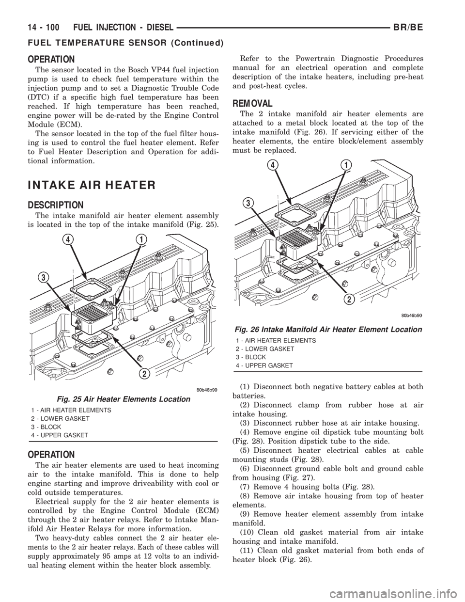
The intake manifold air heater element assembly
is located in the top of the intake manifold (Fig. 25).
OPERATION
The air heater elements are used to heat incoming
air to the intake manifold. This is done to help
engine starting and improve driveability with cool or
cold outside temperatures.
Electrical supply for the 2 air heater elements is
controlled by the Engine Control Module (ECM)
through the 2 air heater relays. Refer to Intake Man-
ifold Air Heater Relays for more information.
Two heavy-duty cables connect the 2 air heater ele-
ments to the 2 air heater relays. Each of these cables will
supply approximately 95 amps at 12 volts to an individ-
ual heating element within the heater block assembly.
Refer to the Powertrain Diagnostic Procedures
manual for an electrical operation and complete
description of the intake heaters, including pre-heat
and post-heat cycles.
REMOVAL
The 2 intake manifold air heater elements are
attached to a metal block located at the top of the
intake manifold (Fig. 26). If servicing either of the
heater elements, the entire block/element assembly
must be replaced.
(1) Disconnect both negative battery cables at both
batteries.
(2) Disconnect clamp from rubber hose at air
intake housing.
(3) Disconnect rubber hose at air intake housing.
(4) Remove engine oil dipstick tube mounting bolt
(Fig. 28). Position dipstick tube to the side.
(5) Disconnect heater electrical cables at cable
mounting studs (Fig. 28).
(6) Disconnect ground cable bolt and ground cable
from housing (Fig. 27).
(7) Remove 4 housing bolts (Fig. 28).
(8) Remove air intake housing from top of heater
elements.
(9) Remove heater element assembly from intake
manifold.
(10) Clean old gasket material from air intake
housing and intake manifold.
(11) Clean old gasket material from both ends of
heater block (Fig. 26).
Fig. 25 Air Heater Elements Location
1 - AIR HEATER ELEMENTS
2 - LOWER GASKET
3 - BLOCK
4 - UPPER GASKET
Fig. 26 Intake Manifold Air Heater Element Location
1 - AIR HEATER ELEMENTS
2 - LOWER GASKET
3 - BLOCK
4 - UPPER GASKET
14 - 100 FUEL INJECTION - DIESELBR/BE
FUEL TEMPERATURE SENSOR (Continued)
Page 1589 of 2889
OPERATION
The Engine Control Module (ECM) operates the 2
heating elements through the 2 intake manifold air
heater relays.
Refer to Powertrain Diagnostic Procedures for an
electrical operation and complete description of the
intake heaters, including pre-heat and post-heat
cycles.
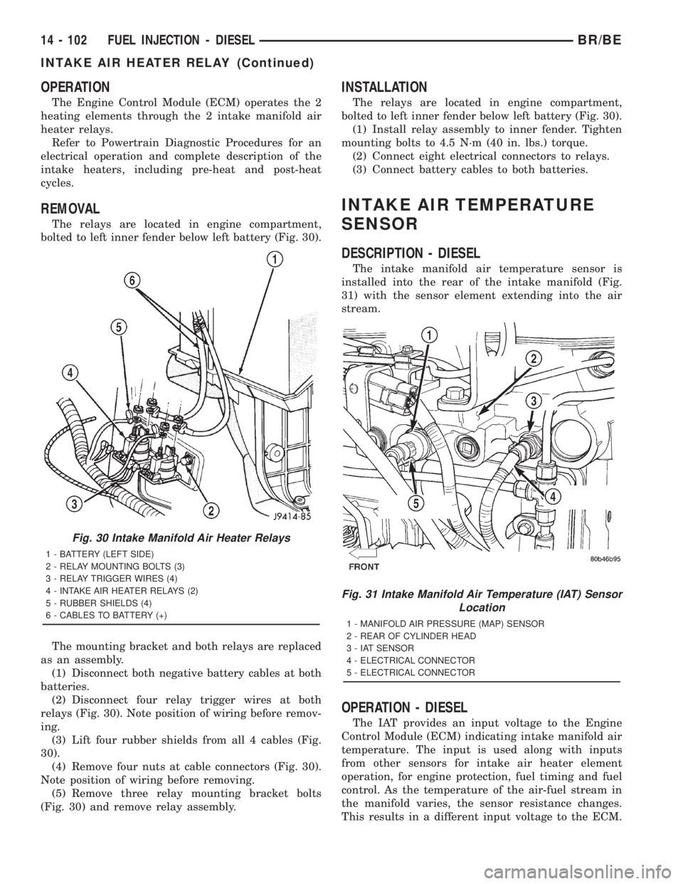
REMOVAL
The relays are located in engine compartment,
bolted to left inner fender below left battery (Fig. 30).
The mounting bracket and both relays are replaced
as an assembly.
(1) Disconnect both negative battery cables at both
batteries.
(2) Disconnect four relay trigger wires at both
relays (Fig. 30). Note position of wiring before remov-
ing.
(3) Lift four rubber shields from all 4 cables (Fig.
30).
(4) Remove four nuts at cable connectors (Fig. 30).
Note position of wiring before removing.
(5) Remove three relay mounting bracket bolts
(Fig. 30) and remove relay assembly.
INSTALLATION
The relays are located in engine compartment,
bolted to left inner fender below left battery (Fig. 30).
(1) Install relay assembly to inner fender. Tighten
mounting bolts to 4.5 N´m (40 in. lbs.) torque.
(2) Connect eight electrical connectors to relays.
(3) Connect battery cables to both batteries.
INTAKE AIR TEMPERATURE
SENSOR
DESCRIPTION - DIESEL
The intake manifold air temperature sensor is
installed into the rear of the intake manifold (Fig.
31) with the sensor element extending into the air
stream.
OPERATION - DIESEL
The IAT provides an input voltage to the Engine
Control Module (ECM) indicating intake manifold air
temperature. The input is used along with inputs
from other sensors for intake air heater element
operation, for engine protection, fuel timing and fuel
control. As the temperature of the air-fuel stream in
the manifold varies, the sensor resistance changes.
This results in a different input voltage to the ECM.
Fig. 30 Intake Manifold Air Heater Relays
1 - BATTERY (LEFT SIDE)
2 - RELAY MOUNTING BOLTS (3)
3 - RELAY TRIGGER WIRES (4)
4 - INTAKE AIR HEATER RELAYS (2)
5 - RUBBER SHIELDS (4)
6 - CABLES TO BATTERY (+)
Fig. 31 Intake Manifold Air Temperature (IAT) Sensor
Location
1 - MANIFOLD AIR PRESSURE (MAP) SENSOR
2 - REAR OF CYLINDER HEAD
3 - IAT SENSOR
4 - ELECTRICAL CONNECTOR
5 - ELECTRICAL CONNECTOR
14 - 102 FUEL INJECTION - DIESELBR/BE
INTAKE AIR HEATER RELAY (Continued)
Page 1590 of 2889
REMOVAL - DIESEL
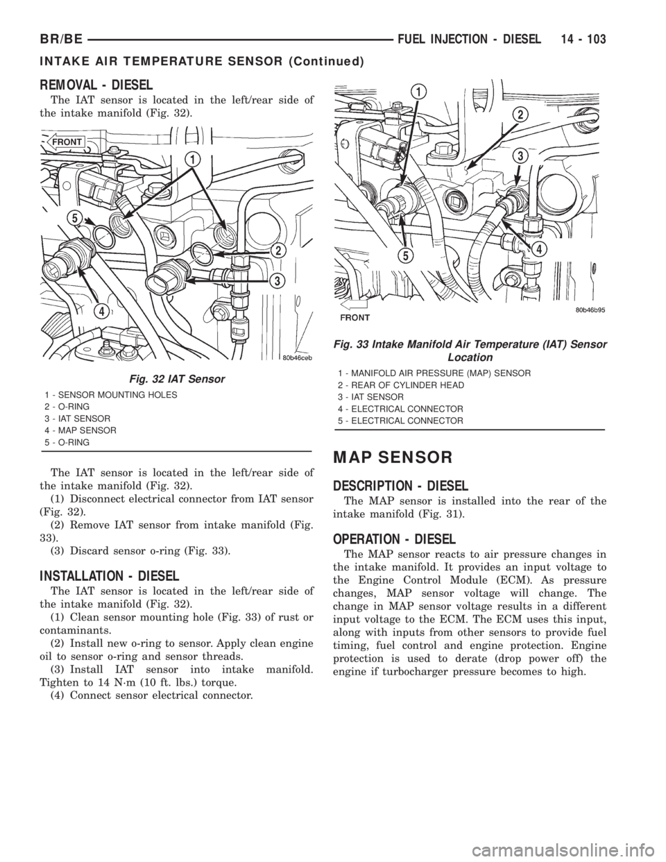
The IAT sensor is located in the left/rear side of
the intake manifold (Fig. 32).
The IAT sensor is located in the left/rear side of
the intake manifold (Fig. 32).
(1) Disconnect electrical connector from IAT sensor
(Fig. 32).
(2) Remove IAT sensor from intake manifold (Fig.
33).
(3) Discard sensor o-ring (Fig. 33).
INSTALLATION - DIESEL
The IAT sensor is located in the left/rear side of
the intake manifold (Fig. 32).
(1) Clean sensor mounting hole (Fig. 33) of rust or
contaminants.
(2) Install new o-ring to sensor. Apply clean engine
oil to sensor o-ring and sensor threads.
(3) Install IAT sensor into intake manifold.
Tighten to 14 N´m (10 ft. lbs.) torque.
(4) Connect sensor electrical connector.
MAP SENSOR
DESCRIPTION - DIESEL
The MAP sensor is installed into the rear of the
intake manifold (Fig. 31).
OPERATION - DIESEL
The MAP sensor reacts to air pressure changes in
the intake manifold. It provides an input voltage to
the Engine Control Module (ECM). As pressure
changes, MAP sensor voltage will change. The
change in MAP sensor voltage results in a different
input voltage to the ECM. The ECM uses this input,
along with inputs from other sensors to provide fuel
timing, fuel control and engine protection. Engine
protection is used to derate (drop power off) the
engine if turbocharger pressure becomes to high.
Fig. 32 IAT Sensor
1 - SENSOR MOUNTING HOLES
2 - O-RING
3 - IAT SENSOR
4 - MAP SENSOR
5 - O-RING
Fig. 33 Intake Manifold Air Temperature (IAT) Sensor
Location
1 - MANIFOLD AIR PRESSURE (MAP) SENSOR
2 - REAR OF CYLINDER HEAD
3 - IAT SENSOR
4 - ELECTRICAL CONNECTOR
5 - ELECTRICAL CONNECTOR
BR/BEFUEL INJECTION - DIESEL 14 - 103
INTAKE AIR TEMPERATURE SENSOR (Continued)
Page 1591 of 2889
REMOVAL - DIESEL
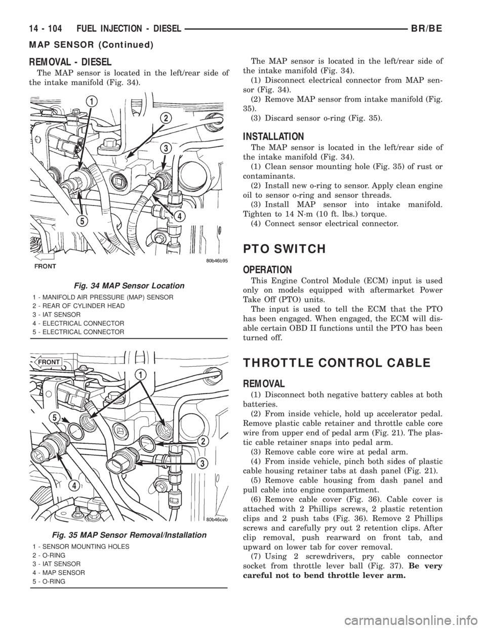
The MAP sensor is located in the left/rear side of
the intake manifold (Fig. 34).The MAP sensor is located in the left/rear side of
the intake manifold (Fig. 34).
(1) Disconnect electrical connector from MAP sen-
sor (Fig. 34).
(2) Remove MAP sensor from intake manifold (Fig.
35).
(3) Discard sensor o-ring (Fig. 35).
INSTALLATION
The MAP sensor is located in the left/rear side of
the intake manifold (Fig. 34).
(1) Clean sensor mounting hole (Fig. 35) of rust or
contaminants.
(2) Install new o-ring to sensor. Apply clean engine
oil to sensor o-ring and sensor threads.
(3) Install MAP sensor into intake manifold.
Tighten to 14 N´m (10 ft. lbs.) torque.
(4) Connect sensor electrical connector.
PTO SWITCH
OPERATION
This Engine Control Module (ECM) input is used
only on models equipped with aftermarket Power
Take Off (PTO) units.
The input is used to tell the ECM that the PTO
has been engaged. When engaged, the ECM will dis-
able certain OBD II functions until the PTO has been
turned off.
THROTTLE CONTROL CABLE
REMOVAL
(1) Disconnect both negative battery cables at both
batteries.
(2) From inside vehicle, hold up accelerator pedal.
Remove plastic cable retainer and throttle cable core
wire from upper end of pedal arm (Fig. 21). The plas-
tic cable retainer snaps into pedal arm.
(3) Remove cable core wire at pedal arm.
(4) From inside vehicle, pinch both sides of plastic
cable housing retainer tabs at dash panel (Fig. 21).
(5) Remove cable housing from dash panel and
pull cable into engine compartment.
(6) Remove cable cover (Fig. 36). Cable cover is
attached with 2 Phillips screws, 2 plastic retention
clips and 2 push tabs (Fig. 36). Remove 2 Phillips
screws and carefully pry out 2 retention clips. After
clip removal, push rearward on front tab, and
upward on lower tab for cover removal.
(7) Using 2 screwdrivers, pry cable connector
socket from throttle lever ball (Fig. 37).Be very
careful not to bend throttle lever arm.
Fig. 34 MAP Sensor Location
1 - MANIFOLD AIR PRESSURE (MAP) SENSOR
2 - REAR OF CYLINDER HEAD
3 - IAT SENSOR
4 - ELECTRICAL CONNECTOR
5 - ELECTRICAL CONNECTOR
Fig. 35 MAP Sensor Removal/Installation
1 - SENSOR MOUNTING HOLES
2 - O-RING
3 - IAT SENSOR
4 - MAP SENSOR
5 - O-RING
14 - 104 FUEL INJECTION - DIESELBR/BE
MAP SENSOR (Continued)
Page 1638 of 2889
The driver selects a particular gear by moving the
shift lever to the desired gear position. This move-
ment moves the internal transmission shift compo-
nents to begin the shift sequence. As the shift lever
moves the selected shift rail, the shift fork attached
to that rail begins to move. The fork is positioned in
a groove in the outer circumference of the synchro-
nizer sleeve. As the shift fork moves the synchronizer
sleeve, the synchronizer begins to speed-up or slow
down the selected gear (depending on whether we are
up-shifting or down-shifting). The synchronizer does
this by having the synchronizer hub splined to the
mainshaft, or the countershaft in some cases, and
moving the blocker ring into contact with the gear's
friction cone. As the blocker ring and friction cone
come together, the gear speed is brought up or down
to the speed of the synchronizer. As the two speeds
match, the splines on the inside of the synchronizer
sleeve become aligned with the teeth on the blocker
ring and the friction cone and eventually will slide
over the teeth, locking the gear to the mainshaft, or
countershaft, through the synchronizer.
DIAGNOSIS AND TESTING - MANUAL
TRANSMISSION
LOW LUBRICANT LEVEL
A low transmission lubricant level is generally the
result of a leak, inadequate lubricant fill or an incor-
rect lubricant level check.
Leaks can occur at the mating surfaces of the gear
case, adaptor or extension housing, or from the front/
rear seals. A suspected leak could also be the result
of an overfill condition.
Leaks at the rear of the extension or adapter hous-
ing will be from the housing oil seals. Leaks at com-
ponent mating surfaces will probably be the result of
inadequate sealer, gaps in the sealer, incorrect bolt
tightening or use of a non-recommended sealer.
A leak at the front of the transmission will be from
either the front bearing retainer or retainer seal.
Lubricant may be seen dripping from the clutch
housing after extended operation. If the leak is
severe, it may also contaminate the clutch disc caus-
ing the disc to slip, grab and or chatter.
A correct lubricant level check can only be made
when the vehicle is level. Also allow the lubricant to
settle for a minute or so before checking. These rec-
ommendations will ensure an accurate check and
avoid an underfill or overfill condition. Always check
the lubricant level after any addition of fluid to avoid
an incorrect lubricant level condition.
HARD SHIFTING
Hard shifting is usually caused by a low lubricant
level, improper or contaminated lubricants. The con-sequence of using non-recommended lubricants is
noise, excessive wear, internal bind and hard shift-
ing. Substantial lubricant leaks can result in gear,
shift rail, synchro, and bearing damage. If a leak
goes undetected for an extended period, the first indi-
cations of component damage are usually hard shift-
ing and noise.
Component damage, incorrect clutch adjustment or
damaged clutch pressure plate or disc are additional
probable causes of increased shift effort. Incorrect
adjustment or a worn/damaged pressure plate or disc
can cause incorrect release. If clutch problem is
advanced, gear clash during shifts can result. Worn
or damaged synchro rings can cause gear clash when
shifting into any forward gear. In some new or
rebuilt transmissions, new synchro rings may tend to
stick slightly causing hard or noisy shifts. In most
cases this condition will decline as the rings wear-in.
TRANSMISSION NOISE
Most manual transmissions make some noise dur-
ing normal operation. Rotating gears generate a mild
whine that is audible, but generally only at extreme
speeds.
Severe highly audible transmission noise is gener-
ally the initial indicator of a lubricant problem.
Insufficient, improper or contaminated lubricant will
promote rapid wear of gears, synchros, shift rails,
forks and bearings. The overheating caused by a
lubricant problem, can also lead to gear breakage.
REMOVAL
(1) Disconnect battery negative cable.
(2) Shift transmission into Neutral.
(3) Remove shift boot bezel screws and slide boot
upward on shift lever extension.
(4) Remove shift lever extension from the shift
tower and lever assembly.
(5) Remove bolts attaching shift tower and lever
assembly to rear case. Then remove shift tower and
lever assembly.
(6) Raise vehicle on hoist.
(7) Remove crankshaft position sensor. Retain sen-
sor attaching bolts.
(8) Remove skid plate, if equipped.
(9) Drain transmission lubricant if transmission
will be disassembled for service.
(10) Mark propeller shaft/shafts and yoke/yokes for
installation reference and remove propeller shaft/
shafts.
(11) Disengage harness from clips on transmission
housing.
(12) Support engine with adjustable jack stand
and wood block.
(13) Drain transmission lubricant if transmission
will be disassembled for service.
BR/BEMANUAL - NV3500 21 - 3
MANUAL - NV3500 (Continued)