2001 DODGE RAM sensor
[x] Cancel search: sensorPage 1520 of 2889
(12) If equipped with vacuum brake booster, verify
that vacuum booster hose is firmly connected to fit-
ting on intake manifold. Also check connection to
brake vacuum booster.
(13) Inspect the air cleaner inlet and air cleaner
element for dirt or restrictions.
(14) Inspect radiator grille area, radiator fins and
air conditioning condenser for restrictions.
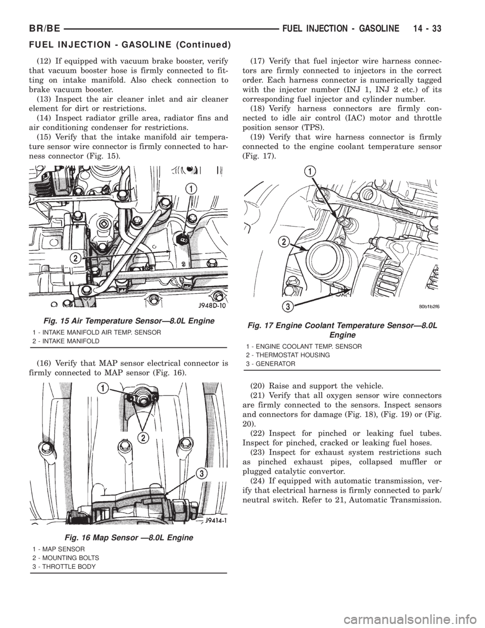
(15) Verify that the intake manifold air tempera-
ture sensor wire connector is firmly connected to har-
ness connector (Fig. 15).
(16) Verify that MAP sensor electrical connector is
firmly connected to MAP sensor (Fig. 16).(17) Verify that fuel injector wire harness connec-
tors are firmly connected to injectors in the correct
order. Each harness connector is numerically tagged
with the injector number (INJ 1, INJ 2 etc.) of its
corresponding fuel injector and cylinder number.
(18) Verify harness connectors are firmly con-
nected to idle air control (IAC) motor and throttle
position sensor (TPS).
(19) Verify that wire harness connector is firmly
connected to the engine coolant temperature sensor
(Fig. 17).
(20) Raise and support the vehicle.
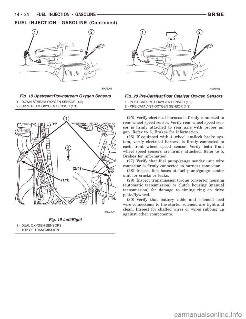
(21) Verify that all oxygen sensor wire connectors
are firmly connected to the sensors. Inspect sensors
and connectors for damage (Fig. 18), (Fig. 19) or (Fig.
20).
(22) Inspect for pinched or leaking fuel tubes.
Inspect for pinched, cracked or leaking fuel hoses.
(23) Inspect for exhaust system restrictions such
as pinched exhaust pipes, collapsed muffler or
plugged catalytic convertor.
(24) If equipped with automatic transmission, ver-
ify that electrical harness is firmly connected to park/
neutral switch. Refer to 21, Automatic Transmission.
Fig. 15 Air Temperature SensorÐ8.0L Engine
1 - INTAKE MANIFOLD AIR TEMP. SENSOR
2 - INTAKE MANIFOLD
Fig. 16 Map Sensor Ð8.0L Engine
1 - MAP SENSOR
2 - MOUNTING BOLTS
3 - THROTTLE BODY
Fig. 17 Engine Coolant Temperature SensorÐ8.0L
Engine
1 - ENGINE COOLANT TEMP. SENSOR
2 - THERMOSTAT HOUSING
3 - GENERATOR
BR/BEFUEL INJECTION - GASOLINE 14 - 33
FUEL INJECTION - GASOLINE (Continued)
Page 1521 of 2889
(25) Verify electrical harness is firmly connected to
rear wheel speed sensor. Verify rear wheel speed sen-
sor is firmly attached to rear axle with proper air
gap. Refer to 5, Brakes for information.
(26) If equipped with 4±wheel antilock brake sys-
tem, verify electrical harness is firmly connected to
each front wheel speed sensor. Verify both front
wheel speed sensors are firmly attached. Refer to 5,
Brakes for information.
(27) Verify that fuel pump/gauge sender unit wire
connector is firmly connected to harness connector.
(28) Inspect fuel hoses at fuel pump/gauge sender
unit for cracks or leaks.
(29) Inspect transmission torque convertor housing
(automatic transmission) or clutch housing (manual
transmission) for damage to timing ring on drive
plate/flywheel.
(30) Verify that battery cable and solenoid feed
wire connections to the starter solenoid are tight and
clean. Inspect for chaffed wires or wires rubbing up
against other components.
Fig. 18 Upstream/Downstream Oxygen Sensors
1 - DOWN STREAM OXYGEN SENSOR (1/2)
2 - UP STREAM OXYGEN SENSOR (1/1)
Fig. 19 Left/Right
1 - DUAL OXYGEN SENSORS
2 - TOP OF TRANSMISSION
Fig. 20 Pre-Catalyst/Post Catalyst Oxygen Sensors
1 - POST CATALYST OXYGEN SENSOR (1/3)
2 - PRE-CATALYST OXYGEN SENSOR (1/2)
14 - 34 FUEL INJECTION - GASOLINEBR/BE
FUEL INJECTION - GASOLINE (Continued)
Page 1522 of 2889
SPECIFICATIONS
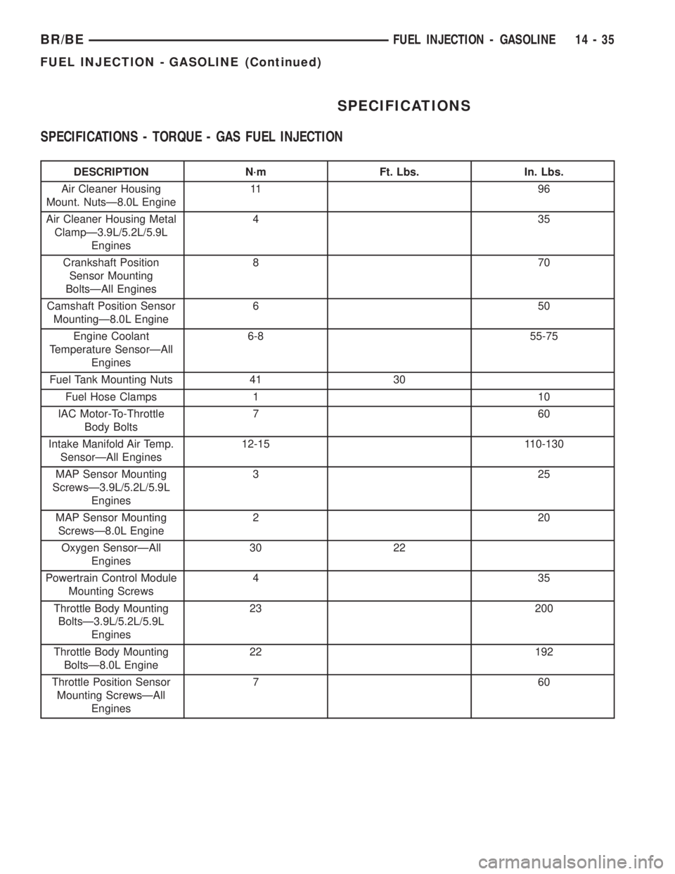
SPECIFICATIONS - TORQUE - GAS FUEL INJECTION
DESCRIPTION N´m Ft. Lbs. In. Lbs.
Air Cleaner Housing
Mount. NutsÐ8.0L Engine11 9 6
Air Cleaner Housing Metal
ClampÐ3.9L/5.2L/5.9L
Engines435
Crankshaft Position
Sensor Mounting
BoltsÐAll Engines870
Camshaft Position Sensor
MountingÐ8.0L Engine650
Engine Coolant
Temperature SensorÐAll
Engines6-8 55-75
Fuel Tank Mounting Nuts 41 30
Fuel Hose Clamps 1 10
IAC Motor-To-Throttle
Body Bolts760
Intake Manifold Air Temp.
SensorÐAll Engines12-15 110-130
MAP Sensor Mounting
ScrewsÐ3.9L/5.2L/5.9L
Engines325
MAP Sensor Mounting
ScrewsÐ8.0L Engine220
Oxygen SensorÐAll
Engines30 22
Powertrain Control Module
Mounting Screws435
Throttle Body Mounting
BoltsÐ3.9L/5.2L/5.9L
Engines23 200
Throttle Body Mounting
BoltsÐ8.0L Engine22 192
Throttle Position Sensor
Mounting ScrewsÐAll
Engines760
BR/BEFUEL INJECTION - GASOLINE 14 - 35
FUEL INJECTION - GASOLINE (Continued)
Page 1523 of 2889
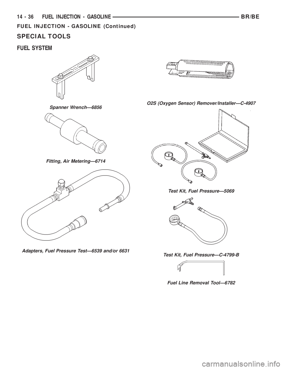
SPECIAL TOOLS
FUEL SYSTEM
Spanner WrenchÐ6856
Fitting, Air MeteringÐ6714
Adapters, Fuel Pressure TestÐ6539 and/or 6631
O2S (Oxygen Sensor) Remover/InstallerÐC-4907
Test Kit, Fuel PressureÐ5069
Test Kit, Fuel PressureÐC-4799-B
Fuel Line Removal ToolÐ6782
14 - 36 FUEL INJECTION - GASOLINEBR/BE
FUEL INJECTION - GASOLINE (Continued)
Page 1525 of 2889
CRANKSHAFT POSITION
SENSOR
DESCRIPTION - 3.9L
The Crankshaft Position (CKP) sensor is located
near the outer edge of the flywheel (starter ringear).
DESCRIPTION - 5.2L/5.9L
The Crankshaft Position (CKP) sensor is located
near the outer edge of the flywheel (starter ringear).
DESCRIPTION - 8.0L
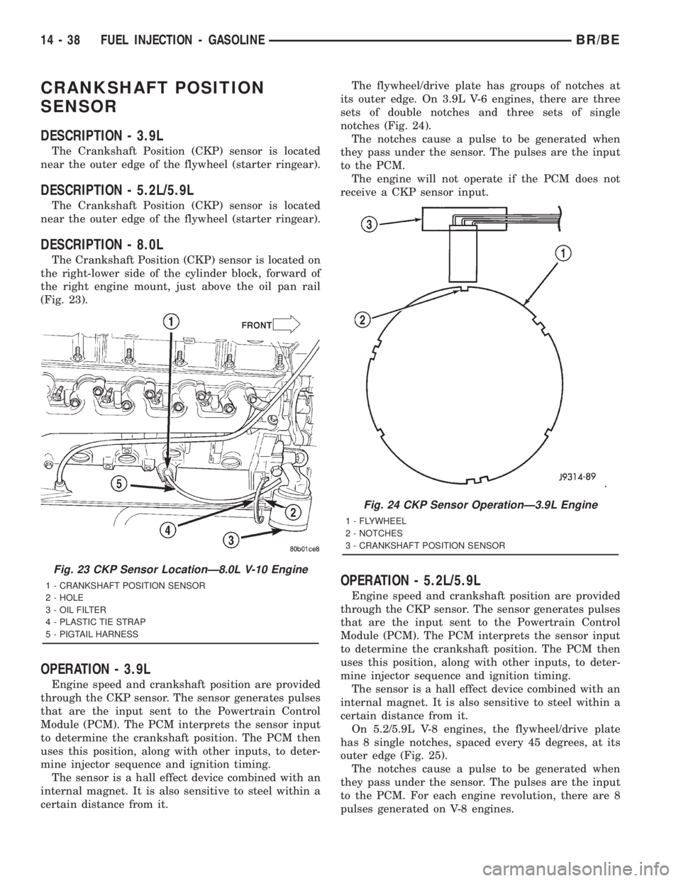
The Crankshaft Position (CKP) sensor is located on
the right-lower side of the cylinder block, forward of
the right engine mount, just above the oil pan rail
(Fig. 23).
OPERATION - 3.9L
Engine speed and crankshaft position are provided
through the CKP sensor. The sensor generates pulses
that are the input sent to the Powertrain Control
Module (PCM). The PCM interprets the sensor input
to determine the crankshaft position. The PCM then
uses this position, along with other inputs, to deter-
mine injector sequence and ignition timing.
The sensor is a hall effect device combined with an
internal magnet. It is also sensitive to steel within a
certain distance from it.The flywheel/drive plate has groups of notches at
its outer edge. On 3.9L V-6 engines, there are three
sets of double notches and three sets of single
notches (Fig. 24).
The notches cause a pulse to be generated when
they pass under the sensor. The pulses are the input
to the PCM.
The engine will not operate if the PCM does not
receive a CKP sensor input.
OPERATION - 5.2L/5.9L
Engine speed and crankshaft position are provided
through the CKP sensor. The sensor generates pulses
that are the input sent to the Powertrain Control
Module (PCM). The PCM interprets the sensor input
to determine the crankshaft position. The PCM then
uses this position, along with other inputs, to deter-
mine injector sequence and ignition timing.
The sensor is a hall effect device combined with an
internal magnet. It is also sensitive to steel within a
certain distance from it.
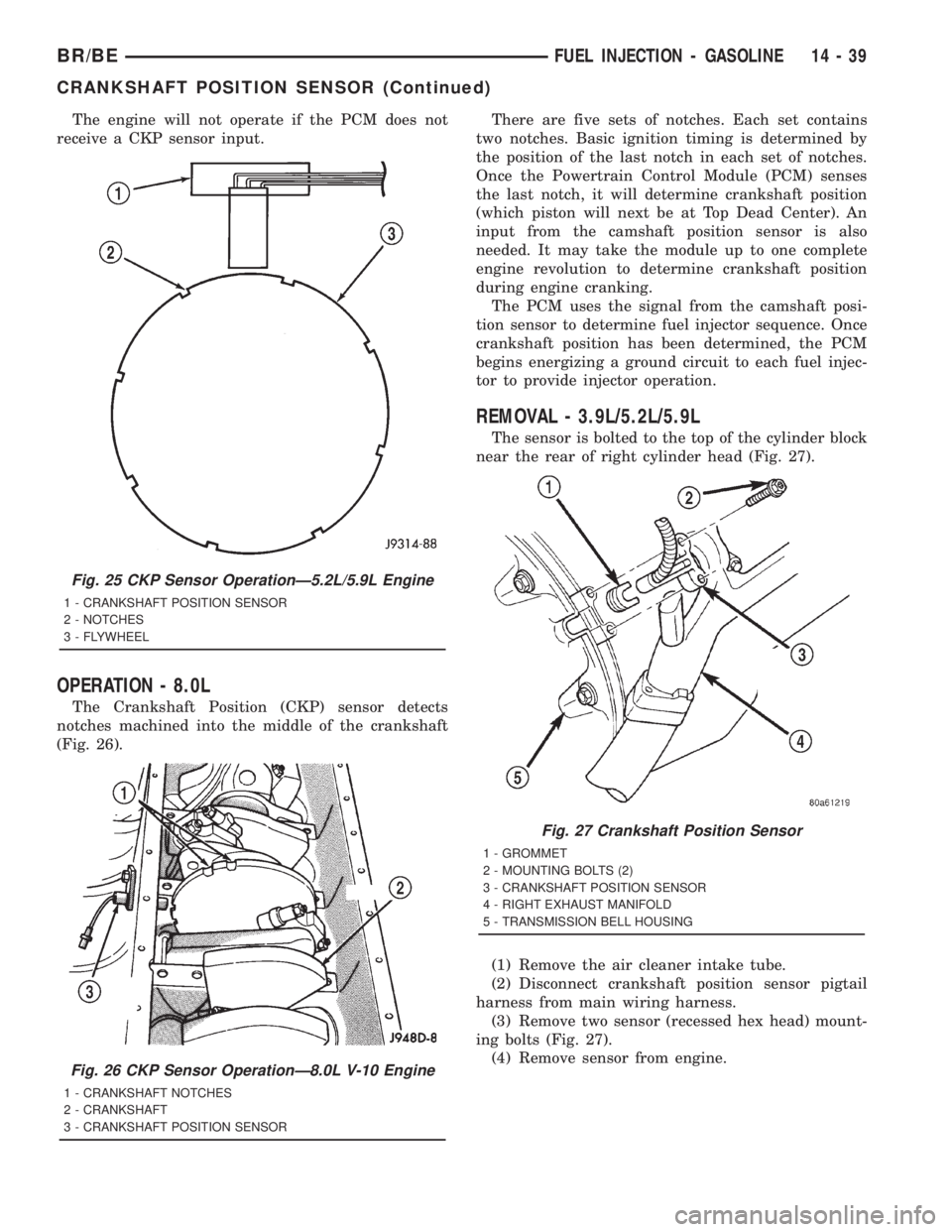
On 5.2/5.9L V-8 engines, the flywheel/drive plate
has 8 single notches, spaced every 45 degrees, at its
outer edge (Fig. 25).
The notches cause a pulse to be generated when
they pass under the sensor. The pulses are the input
to the PCM. For each engine revolution, there are 8
pulses generated on V-8 engines.
Fig. 23 CKP Sensor LocationÐ8.0L V-10 Engine
1 - CRANKSHAFT POSITION SENSOR
2 - HOLE
3 - OIL FILTER
4 - PLASTIC TIE STRAP
5 - PIGTAIL HARNESS
Fig. 24 CKP Sensor OperationÐ3.9L Engine
1 - FLYWHEEL
2 - NOTCHES
3 - CRANKSHAFT POSITION SENSOR
14 - 38 FUEL INJECTION - GASOLINEBR/BE
Page 1526 of 2889
The engine will not operate if the PCM does not
receive a CKP sensor input.
OPERATION - 8.0L
The Crankshaft Position (CKP) sensor detects
notches machined into the middle of the crankshaft
(Fig. 26).There are five sets of notches. Each set contains
two notches. Basic ignition timing is determined by
the position of the last notch in each set of notches.
Once the Powertrain Control Module (PCM) senses
the last notch, it will determine crankshaft position
(which piston will next be at Top Dead Center). An
input from the camshaft position sensor is also
needed. It may take the module up to one complete
engine revolution to determine crankshaft position
during engine cranking.
The PCM uses the signal from the camshaft posi-
tion sensor to determine fuel injector sequence. Once
crankshaft position has been determined, the PCM
begins energizing a ground circuit to each fuel injec-
tor to provide injector operation.
REMOVAL - 3.9L/5.2L/5.9L
The sensor is bolted to the top of the cylinder block
near the rear of right cylinder head (Fig. 27).
(1) Remove the air cleaner intake tube.
(2) Disconnect crankshaft position sensor pigtail
harness from main wiring harness.
(3) Remove two sensor (recessed hex head) mount-
ing bolts (Fig. 27).
(4) Remove sensor from engine.
Fig. 25 CKP Sensor OperationÐ5.2L/5.9L Engine
1 - CRANKSHAFT POSITION SENSOR
2 - NOTCHES
3 - FLYWHEEL
Fig. 26 CKP Sensor OperationÐ8.0L V-10 Engine
1 - CRANKSHAFT NOTCHES
2 - CRANKSHAFT
3 - CRANKSHAFT POSITION SENSOR
Fig. 27 Crankshaft Position Sensor
1 - GROMMET
2 - MOUNTING BOLTS (2)
3 - CRANKSHAFT POSITION SENSOR
4 - RIGHT EXHAUST MANIFOLD
5 - TRANSMISSION BELL HOUSING
BR/BEFUEL INJECTION - GASOLINE 14 - 39
CRANKSHAFT POSITION SENSOR (Continued)
Page 1527 of 2889

REMOVAL - 8.0L
The crankshaft position sensor is located on the
right-lower side of the cylinder block, forward of the
right engine mount, just above the oil pan rail (Fig.
28).
(1) Raise and support vehicle.
(2) Disconnect sensor pigtail harness from main
engine wiring harness.
(3) Remove sensor mounting bolt (Fig. 29).
(4) Cut plastic tie strap (Fig. 28) securing sensor
pigtail harness to side of engine block.
(5) Carefully pry sensor from cylinder block in a
rocking action with two small screwdrivers.
(6) Remove sensor from vehicle.
(7) Check condition of sensor o-ring (Fig. 30).
INSTALLATION - 3.9L/5.2L/5.9L
(1) Position crankshaft position sensor to engine.
(2) Install mounting bolts and tighten to 8 N´m (70
in. lbs.) torque.
(3) Connect main harness electrical connector to
sensor.
(4) Install air cleaner tube.
INSTALLATION - 8.0L
The crankshaft position sensor is located on the
right-lower side of the cylinder block, forward of the
right engine mount, just above the oil pan rail (Fig.
28).(1) Apply a small amount of engine oil to sensor
o-ring (Fig. 30).
(2) Install sensor into cylinder block with a slight
rocking action. Do not twist sensor into position as
damage to o-ring may result.
CAUTION: Before tightening sensor mounting bolt,
be sure sensor is completely flush to cylinder block
(Fig. 29). If sensor is not flush, damage to sensor
mounting tang may result.
(3) Install mounting bolt and tighten to 8 N´m (70
in. lbs.) torque.
(4) Connect sensor pigtail harness to main engine
wiring harness
Fig. 28 Crankshaft Position Sensor LocationÐ8.0L
V-10 Engine
1 - CRANKSHAFT POSITION SENSOR
2 - HOLE
3 - OIL FILTER
4 - PLASTIC TIE STRAP
5 - PIGTAIL HARNESS
Fig. 29 Sensor Removal/InstallationÐ8.0L V-10
Engine
1 - CRANKSHAFT POSITION SENSOR
2 - MOUNTING BOLT
3 - SENSOR POSITIONED FLUSH TO CYLINDER BLOCK
Fig. 30 Sensor O-RingÐ8.0L V-10 Engine
1 - CRANKSHAFT POSITION SENSOR O-RING
2 - ELECTRICAL CONNECTOR
3 - PIGTAIL HARNESS
14 - 40 FUEL INJECTION - GASOLINEBR/BE
CRANKSHAFT POSITION SENSOR (Continued)
Page 1528 of 2889

(5) Install new plastic tie strap (Fig. 28) to secure
sensor pigtail harness to side of engine block. Thread
tie strap through casting hole on cylinder block.
FUEL PUMP RELAY
DESCRIPTION
The 5±pin, 12±volt, fuel pump relay is located in
the Power Distribution Center (PDC). Refer to the
label on the PDC cover for relay location.
OPERATION
The Powertrain Control Module (PCM) energizes
the electric fuel pump through the fuel pump relay.
The fuel pump relay is energized by first applying
battery voltage to it when the ignition key is turned
ON, and then applying a ground signal to the relay
from the PCM.
Whenever the ignition key is turned ON, the elec-
tric fuel pump will operate. But, the PCM will shut-
down the ground circuit to the fuel pump relay in
approximately 1±3 seconds unless the engine is oper-
ating or the starter motor is engaged.
REMOVAL
The fuel pump relay is located in the Power Distri-
bution Center (PDC) (Fig. 31). Refer to label on PDC
cover for relay location.
(1) Remove PDC cover.
(2) Remove relay from PDC.
(3) Check condition of relay terminals and PDC
connector terminals for damage or corrosion. Repair
if necessary before installing relay.
(4) Check for pin height (pin height should be the
same for all terminals within the PDC connector).
Repair if necessary before installing relay.
INSTALLATION
The fuel pump relay is located in the Power Distri-
bution Center (PDC) (Fig. 31). Refer to label on PDC
cover for relay location.
(1) Install relay to PDC.
(2) Install cover to PDC.
IDLE AIR CONTROL MOTOR
DESCRIPTION
The IAC stepper motor is mounted to the throttle
body, and regulates the amount of air bypassing the
control of the throttle plate. As engine loads and
ambient temperatures change, engine rpm changes.
A pintle on the IAC stepper motor protrudes into a
passage in the throttle body, controlling air flow
through the passage. The IAC is controlled by the
Powertrain Control Module (PCM) to maintain the
target engine idle speed.
OPERATION
At idle, engine speed can be increased by retract-
ing the IAC motor pintle and allowing more air to
pass through the port, or it can be decreased by
restricting the passage with the pintle and diminish-
ing the amount of air bypassing the throttle plate.
The IAC is called a stepper motor because it is
moved (rotated) in steps, or increments. Opening the
IAC opens an air passage around the throttle blade
which increases RPM.
The PCM uses the IAC motor to control idle speed
(along with timing) and to reach a desired MAP dur-
ing decel (keep engine from stalling).
The IAC motor has 4 wires with 4 circuits. Two of
the wires are for 12 volts and ground to supply electri-
cal current to the motor windings to operate the step-
per motor in one direction. The other 2 wires are also
for 12 volts and ground to supply electrical current to
operate the stepper motor in the opposite direction.
To make the IAC go in the opposite direction, the
PCM just reverses polarity on both windings. If only
1 wire is open, the IAC can only be moved 1 step
(increment) in either direction. To keep the IAC
motor in position when no movement is needed, the
PCM will energize both windings at the same time.
This locks the IAC motor in place.
In the IAC motor system, the PCM will count
every step that the motor is moved. This allows the
PCM to determine the motor pintle position. If the
memory is cleared, the PCM no longer knows the
position of the pintle. So at the first key ON, the
PCM drives the IAC motor closed, regardless of
where it was before. This zeros the counter. From
this point the PCM will back out the IAC motor and
keep track of its position again.
Fig. 31 Power Distribution Center (PDC)
1 - POWER DISTRIBUTION CENTER (PDC)
BR/BEFUEL INJECTION - GASOLINE 14 - 41
CRANKSHAFT POSITION SENSOR (Continued)