2001 DODGE RAM sensor
[x] Cancel search: sensorPage 1394 of 2889
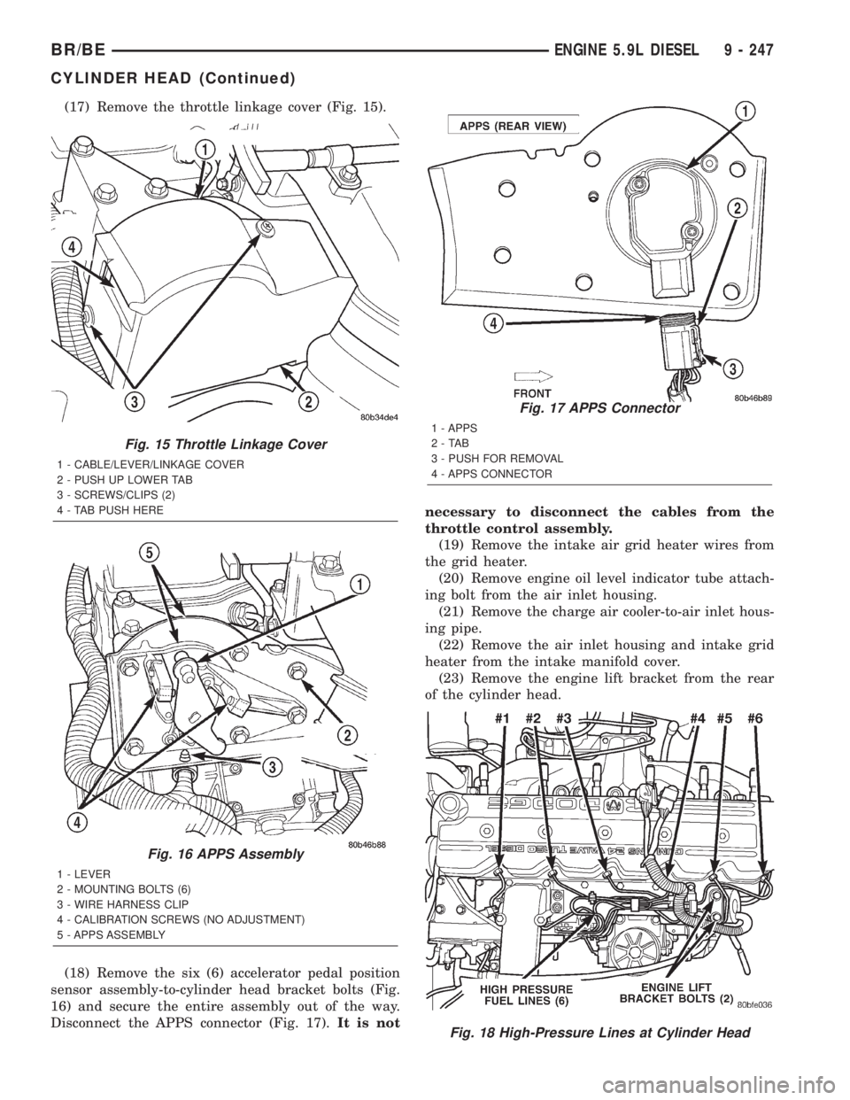
(17) Remove the throttle linkage cover (Fig. 15).
(18) Remove the six (6) accelerator pedal position
sensor assembly-to-cylinder head bracket bolts (Fig.
16) and secure the entire assembly out of the way.
Disconnect the APPS connector (Fig. 17).It is notnecessary to disconnect the cables from the
throttle control assembly.
(19) Remove the intake air grid heater wires from
the grid heater.
(20) Remove engine oil level indicator tube attach-
ing bolt from the air inlet housing.
(21) Remove the charge air cooler-to-air inlet hous-
ing pipe.
(22) Remove the air inlet housing and intake grid
heater from the intake manifold cover.
(23) Remove the engine lift bracket from the rear
of the cylinder head.
Fig. 15 Throttle Linkage Cover
1 - CABLE/LEVER/LINKAGE COVER
2 - PUSH UP LOWER TAB
3 - SCREWS/CLIPS (2)
4 - TAB PUSH HERE
Fig. 16 APPS Assembly
1 - LEVER
2 - MOUNTING BOLTS (6)
3 - WIRE HARNESS CLIP
4 - CALIBRATION SCREWS (NO ADJUSTMENT)
5 - APPS ASSEMBLY
Fig. 17 APPS Connector
1 - APPS
2-TAB
3 - PUSH FOR REMOVAL
4 - APPS CONNECTOR
Fig. 18 High-Pressure Lines at Cylinder Head
BR/BEENGINE 5.9L DIESEL 9 - 247
CYLINDER HEAD (Continued)
Page 1395 of 2889
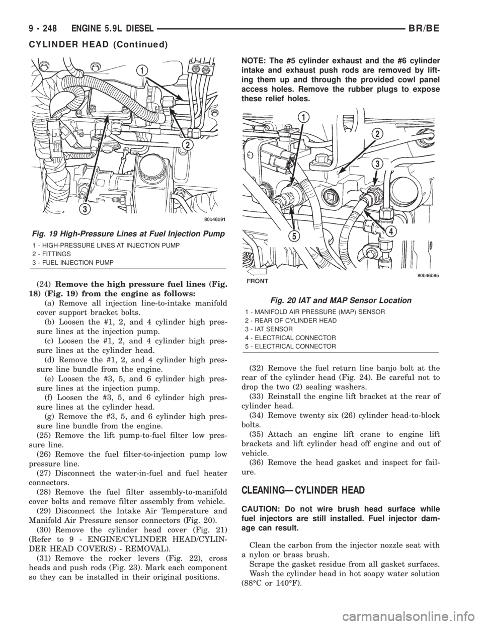
(24)Remove the high pressure fuel lines (Fig.
18) (Fig. 19) from the engine as follows:
(a) Remove all injection line-to-intake manifold
cover support bracket bolts.
(b) Loosen the #1, 2, and 4 cylinder high pres-
sure lines at the injection pump.
(c) Loosen the #1, 2, and 4 cylinder high pres-
sure lines at the cylinder head.
(d) Remove the #1, 2, and 4 cylinder high pres-
sure line bundle from the engine.
(e) Loosen the #3, 5, and 6 cylinder high pres-
sure lines at the injection pump.
(f) Loosen the #3, 5, and 6 cylinder high pres-
sure lines at the cylinder head.
(g) Remove the #3, 5, and 6 cylinder high pres-
sure line bundle from the engine.
(25) Remove the lift pump-to-fuel filter low pres-
sure line.
(26) Remove the fuel filter-to-injection pump low
pressure line.
(27) Disconnect the water-in-fuel and fuel heater
connectors.
(28) Remove the fuel filter assembly-to-manifold
cover bolts and remove filter assembly from vehicle.
(29) Disconnect the Intake Air Temperature and
Manifold Air Pressure sensor connectors (Fig. 20).
(30) Remove the cylinder head cover (Fig. 21)
(Refer to 9 - ENGINE/CYLINDER HEAD/CYLIN-
DER HEAD COVER(S) - REMOVAL).
(31) Remove the rocker levers (Fig. 22), cross
heads and push rods (Fig. 23). Mark each component
so they can be installed in their original positions.NOTE: The #5 cylinder exhaust and the #6 cylinder
intake and exhaust push rods are removed by lift-
ing them up and through the provided cowl panel
access holes. Remove the rubber plugs to expose
these relief holes.
(32) Remove the fuel return line banjo bolt at the
rear of the cylinder head (Fig. 24). Be careful not to
drop the two (2) sealing washers.
(33) Reinstall the engine lift bracket at the rear of
cylinder head.
(34) Remove twenty six (26) cylinder head-to-block
bolts.
(35) Attach an engine lift crane to engine lift
brackets and lift cylinder head off engine and out of
vehicle.
(36) Remove the head gasket and inspect for fail-
ure.
CLEANINGÐCYLINDER HEAD
CAUTION: Do not wire brush head surface while
fuel injectors are still installed. Fuel injector dam-
age can result.
Clean the carbon from the injector nozzle seat with
a nylon or brass brush.
Scrape the gasket residue from all gasket surfaces.
Wash the cylinder head in hot soapy water solution
(88ÉC or 140ÉF).
Fig. 19 High-Pressure Lines at Fuel Injection Pump
1 - HIGH-PRESSURE LINES AT INJECTION PUMP
2 - FITTINGS
3 - FUEL INJECTION PUMP
Fig. 20 IAT and MAP Sensor Location
1 - MANIFOLD AIR PRESSURE (MAP) SENSOR
2 - REAR OF CYLINDER HEAD
3 - IAT SENSOR
4 - ELECTRICAL CONNECTOR
5 - ELECTRICAL CONNECTOR
9 - 248 ENGINE 5.9L DIESELBR/BE
CYLINDER HEAD (Continued)
Page 1398 of 2889
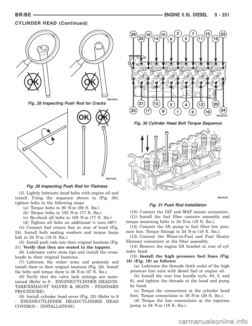
(3) Lightly lubricate head bolts with engine oil and
install. Using the sequence shown in (Fig. 30),
tighten bolts in the following steps:
(a) Torque bolts to 80 N´m (59 ft. lbs.)
(b) Torque bolts to 105 N´m (77 ft. lbs.)
(c) Re-check all bolts to 105 N´m (77 ft. lbs.)
(d) Tighten all bolts an additional ò turn (90É)
(4) Connect fuel return line at rear of head (Fig.
24). Install both sealing washers and torque banjo
bolt to 24 N´m (18 ft. lbs.).
(5)
Install push rods into their original locations (Fig.
31).Verify that they are seated in the tappets
.
(6) Lubricate valve stem tips and install the cross-
heads in their original locations.
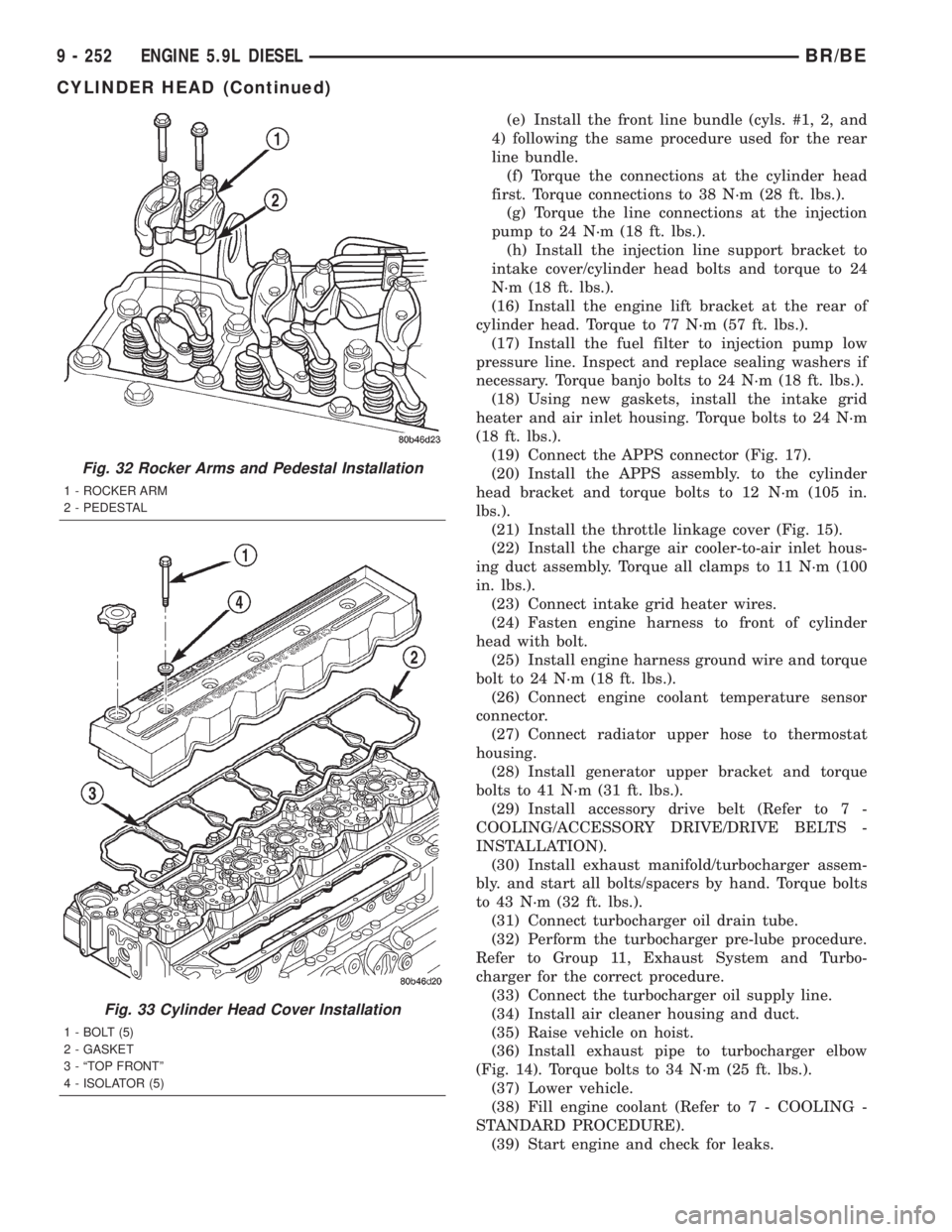
(7)
Lubricate the rocker arms and pedestals and
install them in their original locations (Fig. 32). Install
the bolts and torque them to 36 N´m (27 ft. lbs.).
(8) Verify that the valve lash settings are main-
tained (Refer to 9 - ENGINE/CYLINDER HEAD/IN-
TAKE/EXHAUST VALVES & SEATS - STANDARD
PROCEDURE).
(9) Install cylinder head cover (Fig. 33) (Refer to 9
- ENGINE/CYLINDER HEAD/CYLINDER HEAD
COVER(S) - INSTALLATION).(10) Connect the IAT and MAP sensor connectors.
(11) Install the fuel filter canister assembly and
torque mounting bolts to 24 N´m (18 ft. lbs.).
(12) Connect the lift pump to fuel filter low pres-
sure line. Torque fittings to 24 N´m (18 ft. lbs.).
(13) Connect the Water-in-Fuel and Fuel Heater
Element connectors at the filter assembly.
(14) Remove the engine lift bracket at rear of cyl-
inder head.
(15)Install the high pressure fuel lines (Fig.
18) (Fig. 19) as follows:
(a) Lubricate the threads (both ends) of the high
pressure line nuts with diesel fuel or engine oil.
(b) Install the rear line bundle (cyls. #3, 5, and
6), and tighten the threads at the head and pump
by hand.
(c) Torque the connections at the cylinder head
first. Torque connections to 38 N´m (28 ft. lbs.).
(d) Torque the line connections at the injection
pump to 24 N´m (18 ft. lbs.).
Fig. 28 Inspecting Push Rod for Cracks
Fig. 29 Inspecting Push Rod for Flatness
Fig. 30 Cylinder Head Bolt Torque Sequence
Fig. 31 Push Rod Installation
BR/BEENGINE 5.9L DIESEL 9 - 251
CYLINDER HEAD (Continued)
Page 1399 of 2889
(e) Install the front line bundle (cyls. #1, 2, and
4) following the same procedure used for the rear
line bundle.
(f) Torque the connections at the cylinder head
first. Torque connections to 38 N´m (28 ft. lbs.).
(g) Torque the line connections at the injection
pump to 24 N´m (18 ft. lbs.).
(h) Install the injection line support bracket to
intake cover/cylinder head bolts and torque to 24
N´m (18 ft. lbs.).
(16) Install the engine lift bracket at the rear of
cylinder head. Torque to 77 N´m (57 ft. lbs.).
(17) Install the fuel filter to injection pump low
pressure line. Inspect and replace sealing washers if
necessary. Torque banjo bolts to 24 N´m (18 ft. lbs.).
(18) Using new gaskets, install the intake grid
heater and air inlet housing. Torque bolts to 24 N´m
(18 ft. lbs.).
(19) Connect the APPS connector (Fig. 17).
(20) Install the APPS assembly. to the cylinder
head bracket and torque bolts to 12 N´m (105 in.
lbs.).
(21) Install the throttle linkage cover (Fig. 15).
(22) Install the charge air cooler-to-air inlet hous-
ing duct assembly. Torque all clamps to 11 N´m (100
in. lbs.).
(23) Connect intake grid heater wires.
(24) Fasten engine harness to front of cylinder
head with bolt.
(25) Install engine harness ground wire and torque
bolt to 24 N´m (18 ft. lbs.).
(26) Connect engine coolant temperature sensor
connector.
(27) Connect radiator upper hose to thermostat
housing.
(28) Install generator upper bracket and torque
bolts to 41 N´m (31 ft. lbs.).
(29) Install accessory drive belt (Refer to 7 -
COOLING/ACCESSORY DRIVE/DRIVE BELTS -
INSTALLATION).
(30) Install exhaust manifold/turbocharger assem-
bly. and start all bolts/spacers by hand. Torque bolts
to 43 N´m (32 ft. lbs.).
(31) Connect turbocharger oil drain tube.
(32) Perform the turbocharger pre-lube procedure.
Refer to Group 11, Exhaust System and Turbo-
charger for the correct procedure.
(33) Connect the turbocharger oil supply line.
(34) Install air cleaner housing and duct.
(35) Raise vehicle on hoist.
(36) Install exhaust pipe to turbocharger elbow
(Fig. 14). Torque bolts to 34 N´m (25 ft. lbs.).
(37) Lower vehicle.
(38) Fill engine coolant (Refer to 7 - COOLING -
STANDARD PROCEDURE).
(39) Start engine and check for leaks.
Fig. 32 Rocker Arms and Pedestal Installation
1 - ROCKER ARM
2 - PEDESTAL
Fig. 33 Cylinder Head Cover Installation
1 - BOLT (5)
2 - GASKET
3 - ªTOP FRONTº
4 - ISOLATOR (5)
9 - 252 ENGINE 5.9L DIESELBR/BE
CYLINDER HEAD (Continued)
Page 1442 of 2889
DIAGNOSIS AND TESTINGÐENGINE OIL
PRESSURE
(1) Remove the engine oil pressure sensor and
install Oil Pressure Line and Gauge Tool C-3292 with
a suitable adapter.
(2) Start engine and warm to operating tempera-
ture.
(3) Record engine oil pressure and compare with
engine oil pressure chart.
CAUTION: If engine oil pressure is zero at idle, DO
NOT RUN THE ENGINE.
Engine Oil Pressure (MIN)
At Idle 103.4 kPa (15 psi)
At 2000 rpm 310.2 kPa (45 psi)
If minimum engine oil pressure is below these
ranges, (Refer to 9 - ENGINE - DIAGNOSIS AND
TESTING).
(4) Remove oil pressure gauge and install the oil
pressure sensor. Tighten the sensor to 16 N´m (144
in. lbs.) torque.
OIL
STANDARD PROCEDURE-ENGINE OIL LEVEL
CAUTION: Do not overfill crankcase with engine oil,
oil foaming and oil pressure loss can result.
To ensure proper lubrication of an engine, the
engine oil must be maintained at an acceptable level.
The acceptable oil level is in the SAFE RANGE on
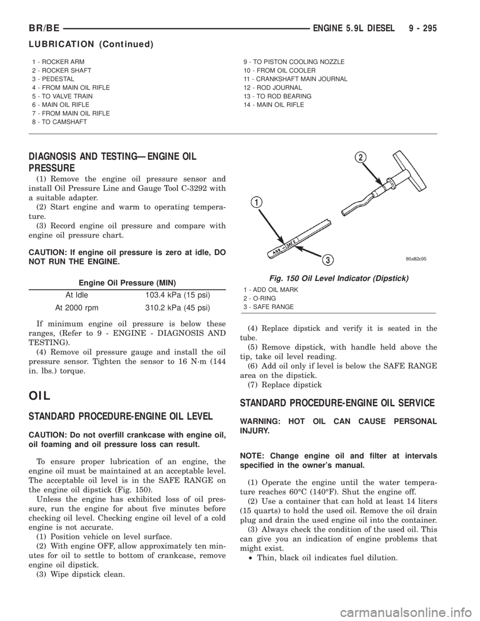
the engine oil dipstick (Fig. 150).
Unless the engine has exhibited loss of oil pres-
sure, run the engine for about five minutes before
checking oil level. Checking engine oil level of a cold
engine is not accurate.
(1) Position vehicle on level surface.
(2) With engine OFF, allow approximately ten min-
utes for oil to settle to bottom of crankcase, remove
engine oil dipstick.
(3) Wipe dipstick clean.(4)
Replace dipstick and verify it is seated in the
tube.
(5) Remove dipstick, with handle held above the
tip, take oil level reading.
(6) Add oil only if level is below the SAFE RANGE
area on the dipstick.
(7) Replace dipstick
STANDARD PROCEDURE-ENGINE OIL SERVICE
WARNING: HOT OIL CAN CAUSE PERSONAL
INJURY.
NOTE: Change engine oil and filter at intervals
specified in the owner's manual.
(1) Operate the engine until the water tempera-
ture reaches 60ÉC (140ÉF). Shut the engine off.
(2) Use a container that can hold at least 14 liters
(15 quarts) to hold the used oil. Remove the oil drain
plug and drain the used engine oil into the container.
(3) Always check the condition of the used oil. This
can give you an indication of engine problems that
might exist.
²Thin, black oil indicates fuel dilution.
1 - ROCKER ARM
2 - ROCKER SHAFT
3 - PEDESTAL
4 - FROM MAIN OIL RIFLE
5 - TO VALVE TRAIN
6 - MAIN OIL RIFLE
7 - FROM MAIN OIL RIFLE
8 - TO CAMSHAFT9 - TO PISTON COOLING NOZZLE
10 - FROM OIL COOLER
11 - CRANKSHAFT MAIN JOURNAL
12 - ROD JOURNAL
13 - TO ROD BEARING
14 - MAIN OIL RIFLE
Fig. 150 Oil Level Indicator (Dipstick)
1 - ADD OIL MARK
2 - O-RING
3 - SAFE RANGE
BR/BEENGINE 5.9L DIESEL 9 - 295
LUBRICATION (Continued)
Page 1445 of 2889
INSTALLATION
(1) Install the plunger, spring, and plug as shown
in (Fig. 152). Tighten the plug to 80 N´m (60 ft. lbs.)
torque.
(2) Connect the battery negative cables.
(3) Start the engine and verify that it has oil pres-
sure.
OIL PRESSURE SENSOR/
SWITCH
DESCRIPTION
The 3±wire, solid-state oil pressure sensor is
installed into the oil pressure galley on the engine
block. It is located below and to the rear of the
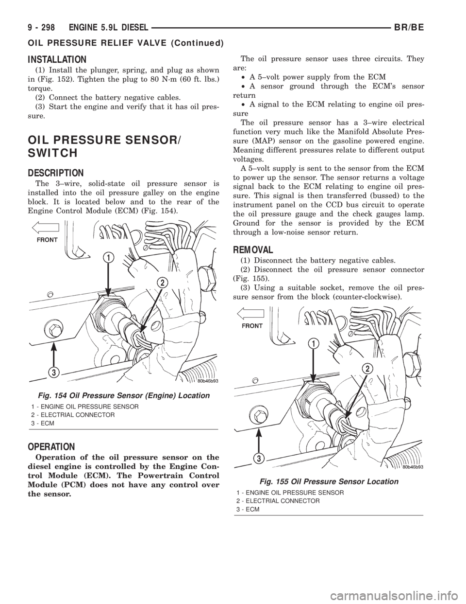
Engine Control Module (ECM) (Fig. 154).
OPERATION
Operation of the oil pressure sensor on the
diesel engine is controlled by the Engine Con-
trol Module (ECM). The Powertrain Control
Module (PCM) does not have any control over
the sensor.The oil pressure sensor uses three circuits. They
are:
²A 5±volt power supply from the ECM
²A sensor ground through the ECM's sensor
return
²A signal to the ECM relating to engine oil pres-
sure
The oil pressure sensor has a 3±wire electrical
function very much like the Manifold Absolute Pres-
sure (MAP) sensor on the gasoline powered engine.
Meaning different pressures relate to different output
voltages.
A 5±volt supply is sent to the sensor from the ECM
to power up the sensor. The sensor returns a voltage
signal back to the ECM relating to engine oil pres-
sure. This signal is then transferred (bussed) to the
instrument panel on the CCD bus circuit to operate
the oil pressure gauge and the check gauges lamp.
Ground for the sensor is provided by the ECM
through a low-noise sensor return.
REMOVAL
(1) Disconnect the battery negative cables.
(2) Disconnect the oil pressure sensor connector
(Fig. 155).
(3) Using a suitable socket, remove the oil pres-
sure sensor from the block (counter-clockwise).
Fig. 154 Oil Pressure Sensor (Engine) Location
1 - ENGINE OIL PRESSURE SENSOR
2 - ELECTRIAL CONNECTOR
3 - ECM
Fig. 155 Oil Pressure Sensor Location
1 - ENGINE OIL PRESSURE SENSOR
2 - ELECTRIAL CONNECTOR
3 - ECM
9 - 298 ENGINE 5.9L DIESELBR/BE
OIL PRESSURE RELIEF VALVE (Continued)
Page 1446 of 2889
INSTALLATION
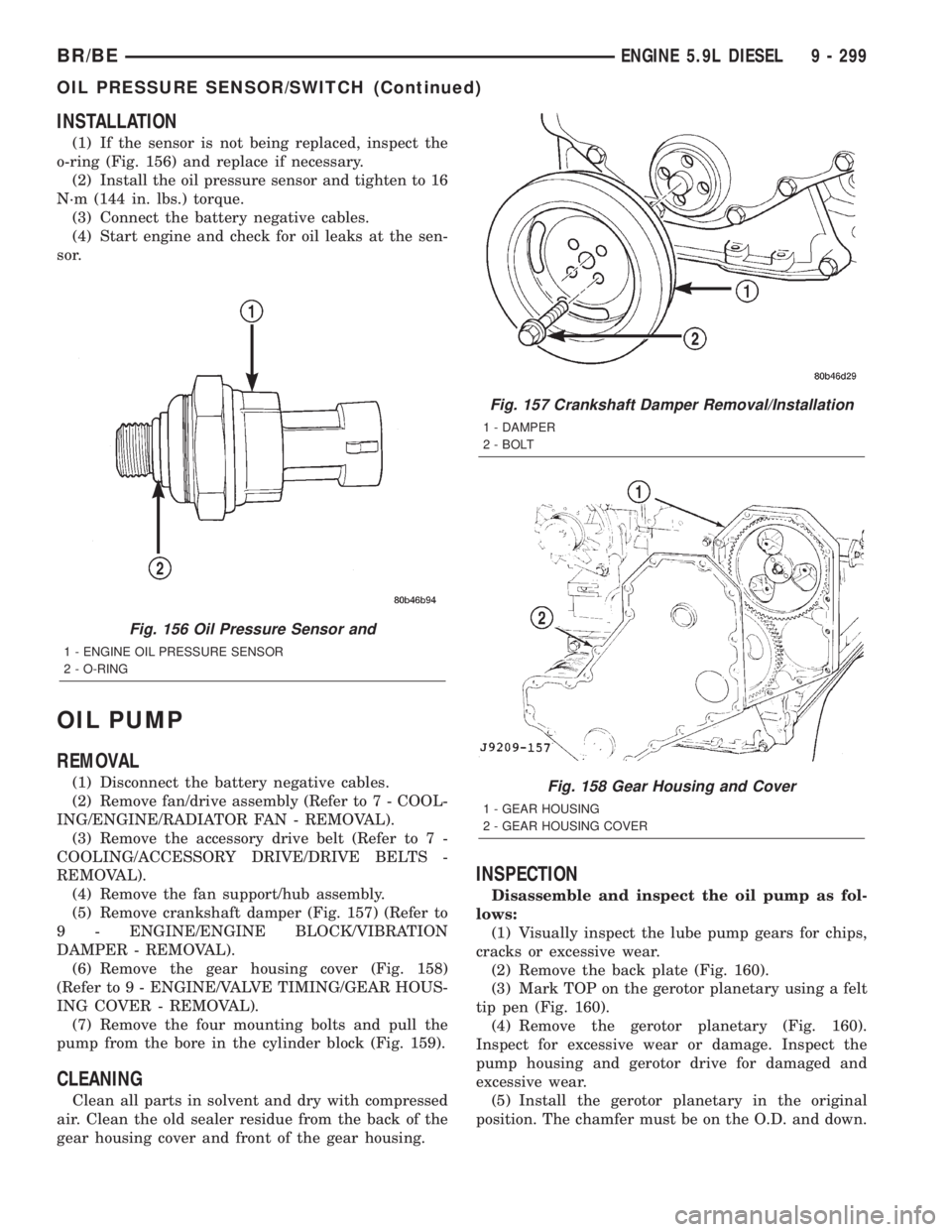
(1) If the sensor is not being replaced, inspect the
o-ring (Fig. 156) and replace if necessary.
(2) Install the oil pressure sensor and tighten to 16
N´m (144 in. lbs.) torque.
(3) Connect the battery negative cables.
(4) Start engine and check for oil leaks at the sen-
sor.
OIL PUMP
REMOVAL
(1) Disconnect the battery negative cables.
(2) Remove fan/drive assembly (Refer to 7 - COOL-
ING/ENGINE/RADIATOR FAN - REMOVAL).
(3) Remove the accessory drive belt (Refer to 7 -
COOLING/ACCESSORY DRIVE/DRIVE BELTS -
REMOVAL).
(4) Remove the fan support/hub assembly.
(5) Remove crankshaft damper (Fig. 157) (Refer to
9 - ENGINE/ENGINE BLOCK/VIBRATION
DAMPER - REMOVAL).
(6) Remove the gear housing cover (Fig. 158)
(Refer to 9 - ENGINE/VALVE TIMING/GEAR HOUS-
ING COVER - REMOVAL).
(7) Remove the four mounting bolts and pull the
pump from the bore in the cylinder block (Fig. 159).
CLEANING
Clean all parts in solvent and dry with compressed
air. Clean the old sealer residue from the back of the
gear housing cover and front of the gear housing.
INSPECTION
Disassemble and inspect the oil pump as fol-
lows:
(1) Visually inspect the lube pump gears for chips,
cracks or excessive wear.
(2) Remove the back plate (Fig. 160).
(3) Mark TOP on the gerotor planetary using a felt
tip pen (Fig. 160).
(4) Remove the gerotor planetary (Fig. 160).
Inspect for excessive wear or damage. Inspect the
pump housing and gerotor drive for damaged and
excessive wear.
(5) Install the gerotor planetary in the original
position. The chamfer must be on the O.D. and down.
Fig. 156 Oil Pressure Sensor and
1 - ENGINE OIL PRESSURE SENSOR
2 - O-RING
Fig. 157 Crankshaft Damper Removal/Installation
1 - DAMPER
2 - BOLT
Fig. 158 Gear Housing and Cover
1 - GEAR HOUSING
2 - GEAR HOUSING COVER
BR/BEENGINE 5.9L DIESEL 9 - 299
OIL PRESSURE SENSOR/SWITCH (Continued)
Page 1452 of 2889
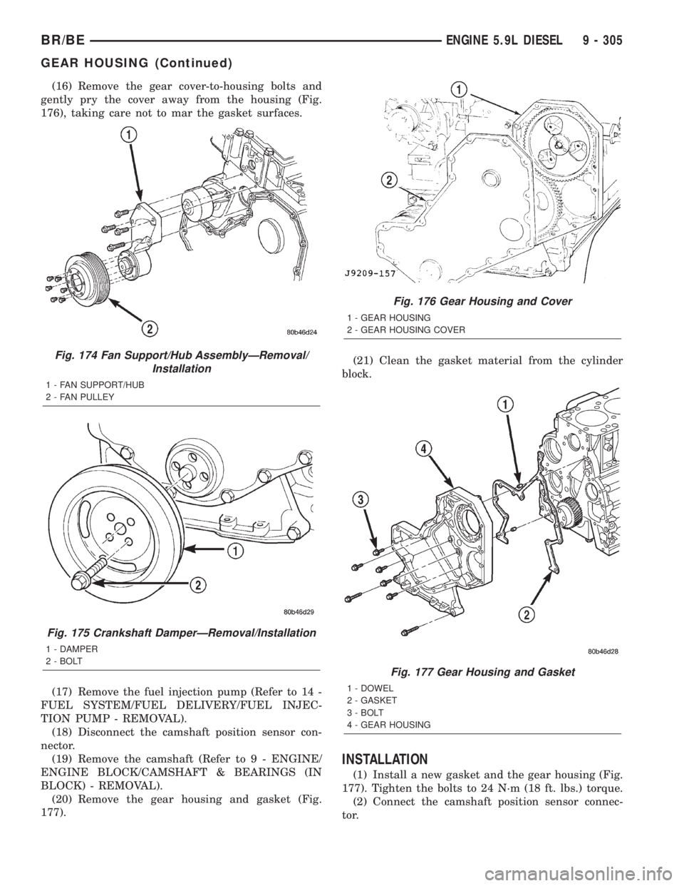
(16) Remove the gear cover-to-housing bolts and
gently pry the cover away from the housing (Fig.
176), taking care not to mar the gasket surfaces.
(17) Remove the fuel injection pump (Refer to 14 -
FUEL SYSTEM/FUEL DELIVERY/FUEL INJEC-
TION PUMP - REMOVAL).
(18) Disconnect the camshaft position sensor con-
nector.
(19) Remove the camshaft (Refer to 9 - ENGINE/
ENGINE BLOCK/CAMSHAFT & BEARINGS (IN
BLOCK) - REMOVAL).
(20) Remove the gear housing and gasket (Fig.
177).(21) Clean the gasket material from the cylinder
block.
INSTALLATION
(1) Install a new gasket and the gear housing (Fig.
177). Tighten the bolts to 24 N´m (18 ft. lbs.) torque.
(2) Connect the camshaft position sensor connec-
tor.
Fig. 174 Fan Support/Hub AssemblyÐRemoval/
Installation
1 - FAN SUPPORT/HUB
2 - FAN PULLEY
Fig. 175 Crankshaft DamperÐRemoval/Installation
1 - DAMPER
2 - BOLT
Fig. 176 Gear Housing and Cover
1 - GEAR HOUSING
2 - GEAR HOUSING COVER
Fig. 177 Gear Housing and Gasket
1 - DOWEL
2 - GASKET
3 - BOLT
4 - GEAR HOUSING
BR/BEENGINE 5.9L DIESEL 9 - 305
GEAR HOUSING (Continued)