2001 DODGE RAM tire pressure
[x] Cancel search: tire pressurePage 276 of 2889
WARNING
WARNING: DUST AND DIRT ACCUMULATING ON
BRAKE PARTS DURING NORMAL USE MAY CON-
TAIN ASBESTOS FIBERS FROM PRODUCTION OR
AFTERMARKET LININGS. BREATHING EXCESSIVE
CONCENTRATIONS OF ASBESTOS FIBERS CAN
CAUSE SERIOUS BODILY HARM. EXERCISE CARE
WHEN SERVICING BRAKE PARTS. DO NOT CLEAN
BRAKE PARTS WITH COMPRESSED AIR OR BY
DRY BRUSHING. USE A VACUUM CLEANER SPE-
CIFICALLY DESIGNED FOR THE REMOVAL OF
ASBESTOS FIBERS FROM BRAKE COMPONENTS.
IF A SUITABLE VACUUM CLEANER IS NOT AVAIL-
ABLE, CLEANING SHOULD BE DONE WITH A
WATER DAMPENED CLOTH. DO NOT SAND, OR
GRIND BRAKE LINING UNLESS EQUIPMENT USED
IS DESIGNED TO CONTAIN THE DUST RESIDUE.
DISPOSE OF ALL RESIDUE CONTAINING ASBES-
TOS FIBERS IN SEALED BAGS OR CONTAINERS
TO MINIMIZE EXPOSURE TO YOURSELF AND OTH-
ERS. FOLLOW PRACTICES PRESCRIBED BY THE
OCCUPATIONAL SAFETY AND HEALTH ADMINIS-
TRATION AND THE ENVIRONMENTAL PROTECTION
AGENCY FOR THE HANDLING, PROCESSING, AND
DISPOSITION OF DUST OR DEBRIS THAT MAY
CONTAIN ASBESTOS FIBERS.
CAUTION: Never use gasoline, kerosene, alcohol,
motor oil, transmission fluid, or any fluid containing
mineral oil to clean the system components. These
fluids damage rubber cups and seals. Use only
fresh brake fluid or Mopar brake cleaner to clean or
flush brake system components. These are the only
cleaning materials recommended. If system contam-
ination is suspected, check the fluid for dirt, discol-
oration, or separation into distinct layers. Also
check the reservoir cap seal for distortion. Drain
and flush the system with new brake fluid if con-
tamination is suspected.
CAUTION: Use Mopar brake fluid, or an equivalent
quality fluid meeting SAE/DOT standards J1703 and
DOT 3. Brake fluid must be clean and free of con-
taminants. Use fresh fluid from sealed containers
only to ensure proper antilock component opera-
tion.
CAUTION: Use Mopar multi-mileage or high temper-
ature grease to lubricate caliper slide surfaces,
drum brake pivot pins, and shoe contact points on
the backing plates. Use multi-mileage grease or GE
661 or Dow 111 silicone grease on caliper slide pins
to ensure proper operation.
DIAGNOSIS AND TESTING - BASE BRAKE
SYSTEM
Base brake components consist of the brake shoes,
calipers, wheel cylinders, brake drums, rotors, brake
lines, master cylinder, booster, and parking brake
components.
Brake diagnosis involves determining if the prob-
lem is related to a mechanical, hydraulic, or vacuum
operated component.
The first diagnosis step is the preliminary check.
PRELIMINARY BRAKE CHECK
(1) Check condition of tires and wheels. Damaged
wheels and worn, damaged, or underinflated tires
can cause pull, shudder, vibration, and a condition
similar to grab.
(2) If complaint was based on noise when braking,
check suspension components. Jounce front and rear
of vehicle and listen for noise that might be caused
by loose, worn or damaged suspension or steering
components.
(3) Inspect brake fluid level and condition. Note
that the brake reservoir fluid level will decrease in
proportion to normal lining wear.Also note that
brake fluid tends to darken over time. This is
normal and should not be mistaken for contam-
ination.
(a) If fluid level is abnormally low, look for evi-
dence of leaks at calipers, wheel cylinders, brake
lines, and master cylinder.
(b) If fluid appears contaminated, drain out a
sample to examine. System will have to be flushed
if fluid is separated into layers, or contains a sub-
stance other than brake fluid. The system seals
and cups will also have to be replaced after flush-
ing. Use clean brake fluid to flush the system.
(4) Check parking brake operation. Verify free
movement and full release of cables and pedal. Also
note if vehicle was being operated with parking
brake partially applied.
(5) Check brake pedal operation. Verify that pedal
does not bind and has adequate free play. If pedal
lacks free play, check pedal and power booster for
being loose or for bind condition. Do not road test
until condition is corrected.
(6) Check booster vacuum check valve and hose.
(7) If components checked appear OK, road test
the vehicle.
ROAD TESTING
(1) If complaint involved low brake pedal, pump
pedal and note if it comes back up to normal height.
(2) Check brake pedal response with transmission
in Neutral and engine running. Pedal should remain
firm under constant foot pressure.
BR/BEBRAKES 5 - 5
HYDRAULIC/MECHANICAL (Continued)
Page 277 of 2889
(3) During road test, make normal and firm brake
stops in 25-40 mph range. Note faulty brake opera-
tion such as low pedal, hard pedal, fade, pedal pulsa-
tion, pull, grab, drag, noise, etc.
(4) Attempt to stop the vehicle with the parking
brake only and note grab, drag, noise, etc.
PEDAL FALLS AWAY
A brake pedal that falls away under steady foot
pressure is generally the result of a system leak. The
leak point could be at a brake line, fitting, hose, or
caliper/wheel cylinder. If leakage is severe, fluid will
be evident at or around the leaking component.
Internal leakage (seal by-pass) in the master cylin-
der caused by worn or damaged piston cups, may
also be the problem cause.
An internal leak in the ABS or RWAL system may
also be the problem with no physical evidence.
LOW PEDAL
If a low pedal is experienced, pump the pedal sev-
eral times. If the pedal comes back up, worn linings,
rotors, drums, or rear brakes out of adjustment are
the most likely causes. The proper course of action is
to inspect and replace all worn component and make
the proper adjustments.
SPONGY PEDAL
A spongy pedal is most often caused by air in the
system. However, thin brake drums or substandard
brake lines and hoses can also cause a spongy pedal.
The proper course of action is to bleed the system,
and replace thin drums and substandard quality
brake hoses if suspected.
HARD PEDAL OR HIGH PEDAL EFFORT
A hard pedal or high pedal effort may be due to
lining that is water soaked, contaminated, glazed, or
badly worn. The power booster or check valve could
also be faulty.
PEDAL PULSATION
Pedal pulsation is caused by components that are
loose, or beyond tolerance limits.
The primary cause of pulsation are disc brake
rotors with excessive lateral runout or thickness vari-
ation, or out of round brake drums. Other causes are
loose wheel bearings or calipers and worn or dam-
aged tires.
NOTE: Some pedal pulsation may be felt during
ABS/EBD activation.BRAKE DRAG
Brake drag occurs when the lining is in constant
contact with the rotor or drum. Drag can occur at one
wheel, all wheels, fronts only, or rears only.
Drag is a product of incomplete brake shoe release.
Drag can be minor or severe enough to overheat the
linings, rotors and drums.
Minor drag will usually cause slight surface char-
ring of the lining. It can also generate hard spots in
rotors and drums from the overheat-cool down pro-
cess. In most cases, the rotors, drums, wheels and
tires are quite warm to the touch after the vehicle is
stopped.
Severe drag can char the brake lining all the way
through. It can also distort and score rotors and
drums to the point of replacement. The wheels, tires
and brake components will be extremely hot. In
severe cases, the lining may generate smoke as it
chars from overheating.
Common causes of brake drag are:
²Seized or improperly adjusted parking brake
cables
²Loose/worn wheel bearing
²Seized caliper or wheel cylinder piston
²Caliper binding on damaged or missing anti-rat-
tle clips or bushings
²Loose caliper mounting
²Drum brake shoes binding on worn/damaged
support plates
²Mis-assembled components
²Long booster output rod
If brake drag occurs at all wheels, the problem
may be related to a blocked master cylinder return
port, or faulty power booster (binds-does not release).
BRAKE FADE
Brake fade is usually a product of overheating
caused by brake drag. However, brake overheating
and resulting fade can also be caused by riding the
brake pedal, making repeated high deceleration stops
in a short time span, or constant braking on steep
mountain roads. Refer to the Brake Drag information
in this section for causes.
BRAKE PULL
Front brake pull condition could result from:
²Contaminated lining in one caliper
²Seized caliper piston
²Binding caliper
²Loose caliper
²Damaged anti-rattle clips
²Improper brake shoes
²Damaged rotor
A worn, damaged wheel bearing or suspension
component are further causes of pull. A damaged
5 - 6 BRAKESBR/BE
HYDRAULIC/MECHANICAL (Continued)
Page 281 of 2889
(4) Have helper press and hold brake pedal to floor
and observe warning light.
(a) If warning light illuminates, switch is operat-
ing correctly.
(b) If light fails to illuminate, check circuit fuse,
bulb, and wiring. The parking brake switch can be
used to aid in identifying whether or not the brake
light bulb and fuse is functional. Repair or replace
parts as necessary and test differential pressure
switch operation again.
(5) If warning light still does not illuminate,
switch is faulty. Replace combination valve assembly,
bleed brake system and verify proper switch and
valve operation.
REMOVAL
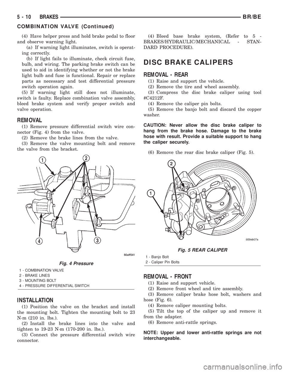
(1) Remove pressure differential switch wire con-
nector (Fig. 4) from the valve.
(2) Remove the brake lines from the valve.
(3) Remove the valve mounting bolt and remove
the valve from the bracket.
INSTALLATION
(1) Position the valve on the bracket and install
the mounting bolt. Tighten the mounting bolt to 23
N´m (210 in. lbs.).
(2) Install the brake lines into the valve and
tighten to 19-23 N´m (170-200 in. lbs.).
(3) Connect the pressure differential switch wire
connector.(4) Bleed base brake system, (Refer to 5 -
BRAKES/HYDRAULIC/MECHANICAL - STAN-
DARD PROCEDURE).
DISC BRAKE CALIPERS
REMOVAL - REAR
(1) Raise and support the vehicle.
(2) Remove the tire and wheel assembly.
(3) Compress the disc brake caliper using tool
#C4212F.
(4) Remove the caliper pin bolts.
(5) Remove the banjo bolt and discard the copper
washer.
CAUTION: Never allow the disc brake caliper to
hang from the brake hose. Damage to the brake
hose with result. Provide a suitable support to hang
the caliper securely.
(6) Remove the rear disc brake caliper (Fig. 5).
REMOVAL - FRONT
(1) Raise and support vehicle.
(2) Remove front wheel and tire assembly.
(3) Remove caliper brake hose bolt, washers and
hose (Fig. 6).
(4) Remove caliper mounting bolts.
(5) Tilt the top of the caliper up and remove it
from the adapter.
(6) Remove anti-rattle springs.
NOTE: Upper and lower anti-rattle springs are not
interchangeable.
Fig. 4 Pressure
1 - COMBINATION VALVE
2 - BRAKE LINES
3 - MOUNTING BOLT
4 - PRESSURE DIFFERENTIAL SWITCH
Fig. 5 REAR CALIPER
1 - Banjo Bolt
2 - Caliper Pin Bolts
5 - 10 BRAKESBR/BE
COMBINATION VALVE (Continued)
Page 303 of 2889
INSTALLATION
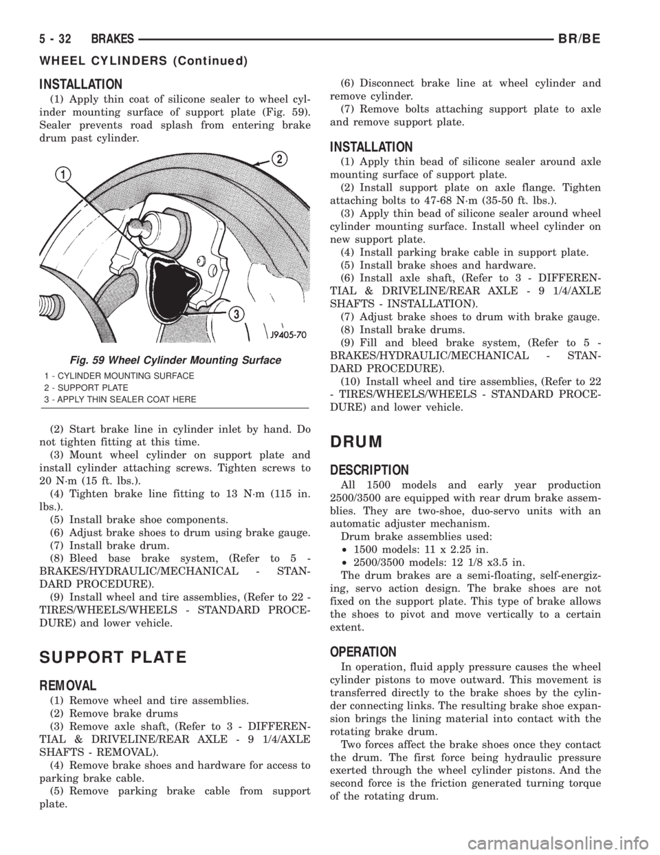
(1) Apply thin coat of silicone sealer to wheel cyl-
inder mounting surface of support plate (Fig. 59).
Sealer prevents road splash from entering brake
drum past cylinder.
(2) Start brake line in cylinder inlet by hand. Do
not tighten fitting at this time.
(3) Mount wheel cylinder on support plate and
install cylinder attaching screws. Tighten screws to
20 N´m (15 ft. lbs.).
(4) Tighten brake line fitting to 13 N´m (115 in.
lbs.).
(5) Install brake shoe components.
(6) Adjust brake shoes to drum using brake gauge.
(7) Install brake drum.
(8) Bleed base brake system, (Refer to 5 -
BRAKES/HYDRAULIC/MECHANICAL - STAN-
DARD PROCEDURE).
(9) Install wheel and tire assemblies, (Refer to 22 -
TIRES/WHEELS/WHEELS - STANDARD PROCE-
DURE) and lower vehicle.
SUPPORT PLATE
REMOVAL
(1) Remove wheel and tire assemblies.
(2) Remove brake drums
(3) Remove axle shaft, (Refer to 3 - DIFFEREN-
TIAL & DRIVELINE/REAR AXLE - 9 1/4/AXLE
SHAFTS - REMOVAL).
(4) Remove brake shoes and hardware for access to
parking brake cable.
(5) Remove parking brake cable from support
plate.(6) Disconnect brake line at wheel cylinder and
remove cylinder.
(7) Remove bolts attaching support plate to axle
and remove support plate.
INSTALLATION
(1) Apply thin bead of silicone sealer around axle
mounting surface of support plate.
(2) Install support plate on axle flange. Tighten
attaching bolts to 47-68 N´m (35-50 ft. lbs.).
(3) Apply thin bead of silicone sealer around wheel
cylinder mounting surface. Install wheel cylinder on
new support plate.
(4) Install parking brake cable in support plate.
(5) Install brake shoes and hardware.
(6) Install axle shaft, (Refer to 3 - DIFFEREN-
TIAL & DRIVELINE/REAR AXLE - 9 1/4/AXLE
SHAFTS - INSTALLATION).
(7) Adjust brake shoes to drum with brake gauge.
(8) Install brake drums.
(9) Fill and bleed brake system, (Refer to 5 -
BRAKES/HYDRAULIC/MECHANICAL - STAN-
DARD PROCEDURE).
(10) Install wheel and tire assemblies, (Refer to 22
- TIRES/WHEELS/WHEELS - STANDARD PROCE-
DURE) and lower vehicle.
DRUM
DESCRIPTION
All 1500 models and early year production
2500/3500 are equipped with rear drum brake assem-
blies. They are two-shoe, duo-servo units with an
automatic adjuster mechanism.
Drum brake assemblies used:
²1500 models: 11 x 2.25 in.
²2500/3500 models: 12 1/8 x3.5 in.
The drum brakes are a semi-floating, self-energiz-
ing, servo action design. The brake shoes are not
fixed on the support plate. This type of brake allows
the shoes to pivot and move vertically to a certain
extent.
OPERATION
In operation, fluid apply pressure causes the wheel
cylinder pistons to move outward. This movement is
transferred directly to the brake shoes by the cylin-
der connecting links. The resulting brake shoe expan-
sion brings the lining material into contact with the
rotating brake drum.
Two forces affect the brake shoes once they contact
the drum. The first force being hydraulic pressure
exerted through the wheel cylinder pistons. And the
second force is the friction generated turning torque
of the rotating drum.
Fig. 59 Wheel Cylinder Mounting Surface
1 - CYLINDER MOUNTING SURFACE
2 - SUPPORT PLATE
3 - APPLY THIN SEALER COAT HERE
5 - 32 BRAKESBR/BE
WHEEL CYLINDERS (Continued)
Page 562 of 2889
²Check Gauges Indicator
²Cruise Indicator (Odometer VFD)
²Four-Wheel Drive Indicator
²High Beam Indicator
²Low Fuel Indicator
²Washer Fluid Indicator
²Malfunction Indicator Lamp (MIL)
²Overdrive-Off Indicator
²Seatbelt Indicator
²Service Reminder Indicator (SRI)
²Transmission Overtemp Indicator
²Turn Signal (Right and Left) Indicators
²Upshift Indicator
²Wait-To-Start Indicator (Diesel Only)
²Water-In-Fuel Indicator (Diesel Only)
Some of these indicators are either programmable
or automatically configured when the EMIC is con-
nected to the vehicle electrical system. This feature
allows those indicators to be activated or deactivated
for compatibility with certain optional equipment.
The EMIC also includes a provision for mounting the
automatic transmission gear selector indicator in the
lower right corner of the cluster. The spring-loaded,
cable driven, mechanical gear selector indicator gives
an indication of the transmission gear that has been
selected with the automatic transmission gear selec-
tor lever. The gear selector indicator pointer is easily
visible through an opening provided in the front of
the cluster overlay, and is also lighted by the cluster
illumination lamps for visibility at night. Models
equipped with a manual transmission have a block-
out plate installed in place of the gear selector indi-
cator.
Cluster illumination is accomplished by adjustable
incandescent back lighting, which illuminates the
gauges for visibility when the exterior lighting is
turned on. The EMIC high beam indicator, turn sig-
nal indicators, and wait-to-start indicator are also
illuminated by dedicated incandescent bulbs. The
remaining indicators in the EMIC are each illumi-
nated by a dedicated Light Emitting Diode (LED)
that is soldered onto the electronic circuit board.
Each of the incandescent bulbs is secured by an inte-
gral bulb holder to the electronic circuit board from
the back of the cluster housing.
Hard wired circuitry connects the EMIC to the
electrical system of the vehicle. These hard wired cir-
cuits are integral to several wire harnesses, which
are routed throughout the vehicle and retained by
many different methods. These circuits may be con-
nected to each other, to the vehicle electrical system
and to the EMIC through the use of a combination of
soldered splices, splice block connectors, and many
different types of wire harness terminal connectors
and insulators. Refer to the appropriate wiring infor-
mation. The wiring information includes wiring dia-grams, proper wire and connector repair procedures,
further details on wire harness routing and reten-
tion, as well as pin-out and location views for the
various wire harness connectors, splices and grounds.
The EMIC modules for this model are serviced only
as complete units. The EMIC module cannot be
adjusted or repaired. If a gauge, an LED indicator,
the VFD, the electronic circuit board, the circuit
board hardware, the cluster overlay, or the EMIC
housing are damaged or faulty, the entire EMIC mod-
ule must be replaced. The cluster lens and hood unit,
the rear cluster housing cover, the automatic trans-
mission gear selector indicator, and the incandescent
lamp bulbs with holders are available for individual
service replacement.
OPERATION
The ElectroMechanical Instrument Cluster (EMIC)
is designed to allow the vehicle operator to monitor
the conditions of many of the vehicle components and
operating systems. The gauges and indicators in the
EMIC provide valuable information about the various
standard and optional powertrains, fuel and emis-
sions systems, cooling systems, lighting systems,
safety systems and many other convenience items.
The EMIC is installed in the instrument panel so
that all of these monitors can be easily viewed by the
vehicle operator when driving, while still allowing
relative ease of access for service. The microproces-
sor-based EMIC hardware and software uses various
inputs to control the gauges and indicators visible on
the face of the cluster. Some of these inputs are hard
wired, but most are in the form of electronic mes-
sages that are transmitted by other electronic mod-
ules over the Chrysler Collision Detection (CCD) data
bus network. (Refer to 8 - ELECTRICAL/ELEC-
TRONIC CONTROL MODULES/COMMUNICATION
- OPERATION).
The EMIC microprocessor smooths the input data
using algorithms to provide gauge readings that are
accurate, stable and responsive to operating condi-
tions. These algorithms are designed to provide
gauge readings during normal operation that are con-
sistent with customer expectations. However, when
abnormal conditions exist, such as low/high battery
voltage, low oil pressure, or high coolant tempera-
ture, the algorithm drives the gauge pointer to an
extreme position and the microprocessor turns on the
Check Gauges indicator to provide a distinct visual
indication of a problem to the vehicle operator. The
instrument cluster circuitry may also generate a
hard wired chime tone request to the Central Timer
Module (CTM) when it monitors certain conditions or
inputs, in order to provide the vehicle operator with
an audible alert.
BR/BEINSTRUMENT CLUSTER 8J - 3
INSTRUMENT CLUSTER (Continued)
Page 657 of 2889
the suspect transmitter does not, replace the faulty
RKE transmitter.
NOTE: Be certain to perform the RKE Transmitter
Programming procedure again following this test.
This procedure will erase the access code of the
test transmitter from the RKE receiver.
STANDARD PROCEDURE - RKE TRANSMITTER
PROGRAMMING
To program the Remote Keyless Entry (RKE)
transmitter access codes into the RKE receiver in the
high-line or premium Central Timer Module (CTM)
requires the use of a DRBIIItscan tool. Refer to the
appropriate diagnostic information.
STANDARD PROCEDURE - RKE TRANSMITTER
BATTERIES
The Remote Keyless Entry (RKE) transmitter case
snaps open and shut for battery access. To replace
the RKE transmitter batteries:
(1) Using a trim stick or a thin coin, gently pry at
the notch in the center seam of the RKE transmitter
case halves located near the key ring until the two
halves unsnap.
(2) Lift the back half of the transmitter case off of
the RKE transmitter.
(3) Remove the two batteries from the RKE trans-
mitter.
(4) Replace the two batteries with new Duracell
DL2016, or their equivalent. Be certain that the bat-
teries are installed with their polarity correctly ori-
ented.
(5) Align the two RKE transmitter case halves
with each other, and squeeze them firmly and evenly
together using hand pressure until they snap back
into place.
POWER LOCK SWITCH
DESCRIPTION
The power lock system can be controlled by a two-
way momentary switch integral to the power window
and lock switch and bezel unit on the trim panel of
each front door. Each power lock switch is illumi-
nated by a Light-Emitting Diode (LED) that is inte-
gral to the switch paddle. The LED of each switch is
illuminated whenever the ignition switch is in the
On position.
The power lock switches and their LEDs cannot be
adjusted or repaired and, if faulty or damaged, the
entire power window and lock switch and bezel unit
must be replaced.
OPERATION
On models with a base version of the Central
Timer Module (CTM), the power lock switches are
hard-wired to the power lock motors. The power lock
switch provides the correct battery and ground feeds
to the power lock motors to lock or unlock the door
latches.
On models with a high-line or premium version of
the CTM, the power lock switch controls battery cur-
rent signals to the lock and unlock sense inputs of
the CTM. The CTM then relays the correct battery
and ground feeds to the power lock motors to lock or
unlock the door latches.
DIAGNOSIS AND TESTING - POWER LOCK
SWITCH
The Light-Emitting Diode (LED) illumination
lamps for all of the power window and lock switch
and bezel unit switch paddles receive battery current
through the power window circuit breaker in the
Junction Block (JB). If all of the LEDs are inopera-
tive in either or both power window and lock switch
and bezel units, be certain to diagnose the power
window system before replacing the switch unit.
(Refer to 8 - ELECTRICAL/POWER WINDOWS -
DIAGNOSIS AND TESTING). If only one LED in a
power window and lock switch and bezel unit is inop-
erative, replace the faulty switch and bezel unit.
Refer to the appropriate wiring information. The wir-
ing information includes wiring diagrams, proper
wire and connector repair procedures, details of wire
harness routing and retention, connector pin-out
information and location views for the various wire
harness connectors, splices and grounds.
(1) Check the fused B(+) fuse (Fuse 13 - 10
ampere) in the Junction Block (JB). If OK, go to Step
2. If not OK, repair the shorted circuit or component
as required and replace the faulty fuse.
(2) Check for battery voltage at the fused B(+) fuse
(Fuse 13 - 10 ampere) in the JB. If OK, go to Step 3.
If not OK, repair the open fused B(+) circuit between
the JB and the Power Distribution Center (PDC) as
required.
(3) Disconnect and isolate the battery negative
cable. Remove the power window and lock switch and
bezel unit from the door trim panel. Disconnect the
door wire harness connector for the power window
and lock switch unit from the switch connector recep-
tacle.
(4) Reconnect the battery negative cable. Check for
battery voltage at the fused B(+) circuit cavity of the
door wire harness connector for the power window
and lock switch unit. If OK, go to Step 5. If not OK,
repair the open fused B(+) circuit between the power
window and lock switch unit and the JB as required.
8N - 8 POWER LOCKSBR/BE
REMOTE KEYLESS ENTRY TRANSMITTER (Continued)
Page 732 of 2889
be routed away from hot, sharp, or moving parts;
and, sharp bends that might pinch the hose must be
avoided.
WASHER NOZZLE
DESCRIPTION
The two washer nozzles have integral snap fea-
tures that secure them in dedicated holes in the cowl
plenum cover/grille panel located near the base of the
windshield. The domed upper surface of the washer
nozzle is visible on the top of the plenum cover/grille
panel, and the nozzle orifice is oriented towards the
windshield glass. The washer plumbing fittings for
the washer nozzles are concealed beneath the cowl
plenum cover/grille panel. These fluidic washer noz-
zles are constructed of molded plastic. The cowl ple-
num cover/grille panel must be removed from the
vehicle to access the nozzles for service. The washer
nozzles cannot be adjusted or repaired and, if faulty
or damaged, they must be replaced.
OPERATION
The two washer nozzles are designed to dispense
washer fluid into the wiper pattern area on the out-
side of the windshield glass. Pressurized washer fluid
is fed to each nozzle from the washer reservoir by the
washer pump/motor through rubber hoses, which are
attached to a barbed nipple on each washer nozzle
below the cowl plenum cover/grille panel. The washer
nozzles incorporate a fluidic design, which causes the
nozzle to emit the pressurized washer fluid as an
oscillating stream to more effectively cover a larger
area of the glass area to be cleaned.
REMOVAL
(1) Remove the cowl plenum cover/grille panel
from the cowl top. (Refer to 23 - BODY/EXTERIOR/
COWL GRILLE - REMOVAL).
(2) From the underside of the cowl plenum cover/
grille panel, disconnect the washer hose from the
nozzle fitting.
(3) From the underside of the cowl plenum cover/
grille panel, compress the snap features of the
washer nozzle and push the nozzle out through the
top of the panel.
INSTALLATION
(1) From the top of the cowl plenum cover/grille
panel, insert the barbed nipple of the washer nozzle
through the nozzle mounting hole.
(2) With the orifice of the washer nozzle oriented
toward the windshield, use hand pressure to push
the nozzle into the mounting hole until the snap fea-tures of the nozzle are fully engaged with the under-
side of the cowl plenum cover/grille panel.
(3) From the underside of the cowl plenum cover/
grille panel, reconnect the washer hose to the washer
nozzle fitting.
(4) Reinstall the cowl plenum cover/grille panel
onto the cowl top. (Refer to 23 - BODY/EXTERIOR/
COWL GRILLE - INSTALLATION).
WASHER PUMP/MOTOR
DESCRIPTION
The washer pump/motor unit is located on the rear
of the washer reservoir, near the bottom in the left
front corner of the engine compartment. A small per-
manently lubricated and sealed electric motor is cou-
pled to the rotor-type washer pump. A seal flange
with a large barbed inlet nipple on the pump housing
passes through a rubber grommet seal installed in
the dedicated mounting hole near the bottom of the
washer reservoir. A smaller barbed outlet nipple on
the pump housing connects the unit to the washer
hose. The washer pump/motor unit is retained on the
reservoir by the interference fit between the barbed
pump inlet nipple and the grommet seal, which is a
light press fit. An integral electrical connector recep-
tacle is located on the motor housing. The washer
pump/motor unit cannot be repaired. If faulty or
damaged, the entire washer pump/motor unit must
be replaced.
OPERATION
The washer pump/motor unit is connected to the
vehicle electrical system through a single take out
and two-cavity connector of the headlamp and dash
wire harness. The washer pump/motor is grounded at
all times through a take out of the headlamp and
dash wire harness with a single eyelet terminal con-
nector that is secured by a nut to a ground stud
located on the forward extension of the left front
fender wheel housing in the engine compartment.
The washer pump/motor receives battery current on
a fused ignition switch output (run-acc) circuit
through the closed contacts of the momentary washer
switch within the multi-function switch only when
the washer button on the end of the switch control
stalk is depressed towards the steering column.
Washer fluid is gravity-fed from the washer reservoir
to the inlet side of the washer pump. When the pump
motor is energized, the rotor-type pump pressurizes
the washer fluid and forces it through the pump out-
let nipple, the washer plumbing, and the washer noz-
zles onto the windshield glass.
BR/BEWIPERS/WASHERS 8R - 9
WASHER HOSES/TUBES (Continued)
Page 734 of 2889
COOLING - STANDARD PROCEDURE - DRAIN/
DIESEL ENGINE).
(3) Disconnect the upper radiator hose from the
radiator.
(4) Disconnect the headlamp and dash wire har-
ness connector for the washer fluid level switch from
the switch connector receptacle.
(5) Disconnect the headlamp and dash wire har-
ness connector for the washer pump/motor unit from
the motor connector receptacle.
(6) Disconnect the washer hose from the barbed
outlet nipple of the washer pump/motor and allow
the washer fluid to drain into a clean container for
reuse.
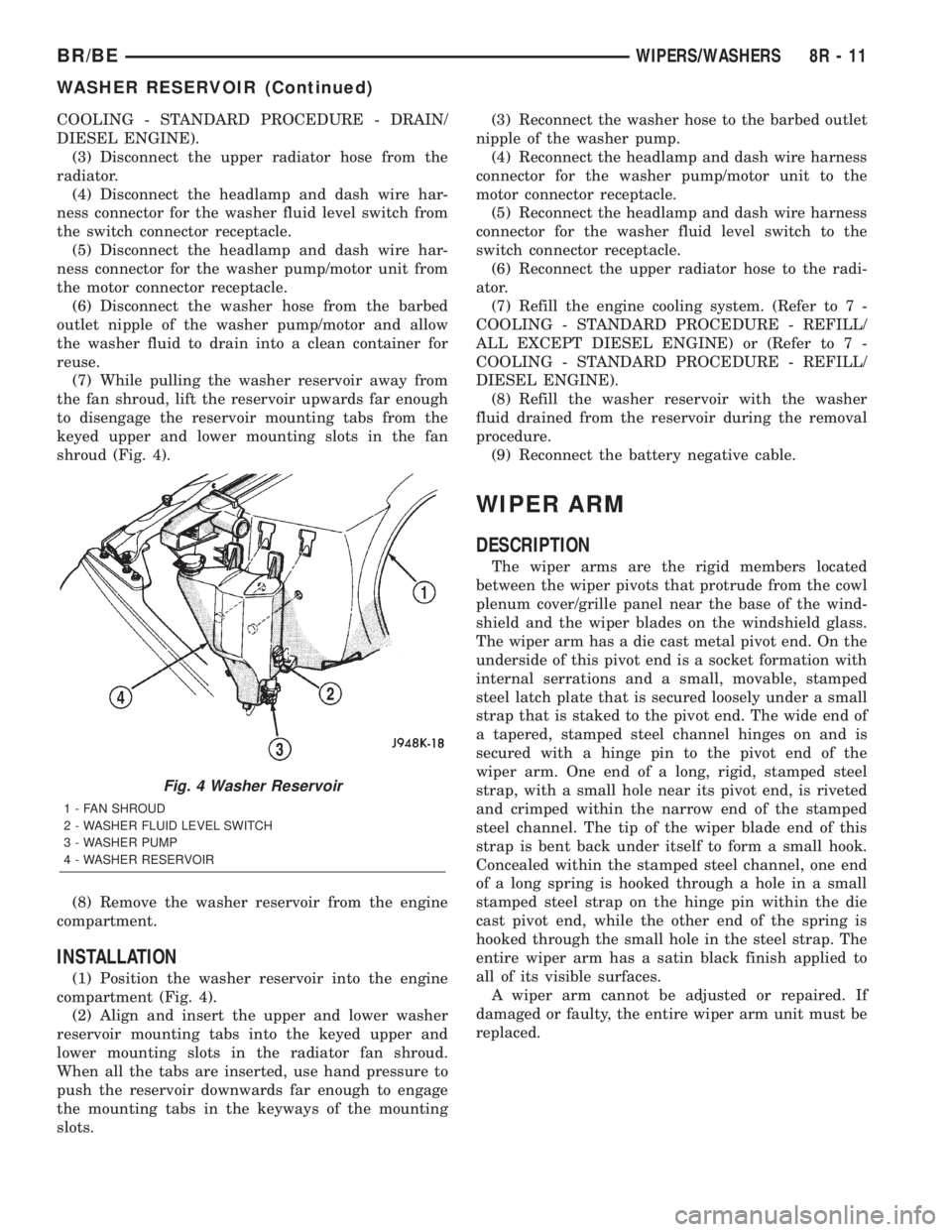
(7) While pulling the washer reservoir away from
the fan shroud, lift the reservoir upwards far enough
to disengage the reservoir mounting tabs from the
keyed upper and lower mounting slots in the fan
shroud (Fig. 4).
(8) Remove the washer reservoir from the engine
compartment.
INSTALLATION
(1) Position the washer reservoir into the engine
compartment (Fig. 4).
(2) Align and insert the upper and lower washer
reservoir mounting tabs into the keyed upper and
lower mounting slots in the radiator fan shroud.
When all the tabs are inserted, use hand pressure to
push the reservoir downwards far enough to engage
the mounting tabs in the keyways of the mounting
slots.(3) Reconnect the washer hose to the barbed outlet
nipple of the washer pump.
(4) Reconnect the headlamp and dash wire harness
connector for the washer pump/motor unit to the
motor connector receptacle.
(5) Reconnect the headlamp and dash wire harness
connector for the washer fluid level switch to the
switch connector receptacle.
(6) Reconnect the upper radiator hose to the radi-
ator.
(7) Refill the engine cooling system. (Refer to 7 -
COOLING - STANDARD PROCEDURE - REFILL/
ALL EXCEPT DIESEL ENGINE) or (Refer to 7 -
COOLING - STANDARD PROCEDURE - REFILL/
DIESEL ENGINE).
(8) Refill the washer reservoir with the washer
fluid drained from the reservoir during the removal
procedure.
(9) Reconnect the battery negative cable.
WIPER ARM
DESCRIPTION
The wiper arms are the rigid members located
between the wiper pivots that protrude from the cowl
plenum cover/grille panel near the base of the wind-
shield and the wiper blades on the windshield glass.
The wiper arm has a die cast metal pivot end. On the
underside of this pivot end is a socket formation with
internal serrations and a small, movable, stamped
steel latch plate that is secured loosely under a small
strap that is staked to the pivot end. The wide end of
a tapered, stamped steel channel hinges on and is
secured with a hinge pin to the pivot end of the
wiper arm. One end of a long, rigid, stamped steel
strap, with a small hole near its pivot end, is riveted
and crimped within the narrow end of the stamped
steel channel. The tip of the wiper blade end of this
strap is bent back under itself to form a small hook.
Concealed within the stamped steel channel, one end
of a long spring is hooked through a hole in a small
stamped steel strap on the hinge pin within the die
cast pivot end, while the other end of the spring is
hooked through the small hole in the steel strap. The
entire wiper arm has a satin black finish applied to
all of its visible surfaces.
A wiper arm cannot be adjusted or repaired. If
damaged or faulty, the entire wiper arm unit must be
replaced.
Fig. 4 Washer Reservoir
1 - FAN SHROUD
2 - WASHER FLUID LEVEL SWITCH
3 - WASHER PUMP
4 - WASHER RESERVOIR
BR/BEWIPERS/WASHERS 8R - 11
WASHER RESERVOIR (Continued)