2001 DODGE RAM tire pressure
[x] Cancel search: tire pressurePage 2229 of 2889
by a clutch disc until entire clutch pack is installed
(4 discs and 3 plates are required) (Fig. 223).
(13) Install the reaction plate.
(14) Install selective snap-ring. Be sure snap-ring
is fully seated in retainer groove.
(15) Using a suitable gauge bar and dial indicator,
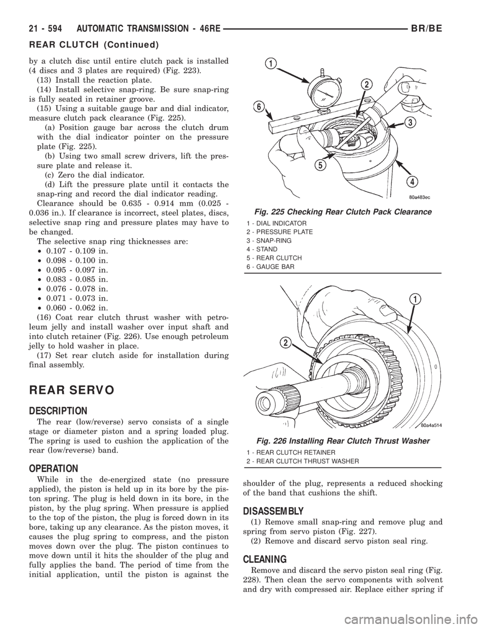
measure clutch pack clearance (Fig. 225).
(a) Position gauge bar across the clutch drum
with the dial indicator pointer on the pressure
plate (Fig. 225).
(b) Using two small screw drivers, lift the pres-
sure plate and release it.
(c) Zero the dial indicator.
(d) Lift the pressure plate until it contacts the
snap-ring and record the dial indicator reading.
Clearance should be 0.635 - 0.914 mm (0.025 -
0.036 in.). If clearance is incorrect, steel plates, discs,
selective snap ring and pressure plates may have to
be changed.
The selective snap ring thicknesses are:
²0.107 - 0.109 in.
²0.098 - 0.100 in.
²0.095 - 0.097 in.
²0.083 - 0.085 in.
²0.076 - 0.078 in.
²0.071 - 0.073 in.
²0.060 - 0.062 in.
(16) Coat rear clutch thrust washer with petro-
leum jelly and install washer over input shaft and
into clutch retainer (Fig. 226). Use enough petroleum
jelly to hold washer in place.
(17) Set rear clutch aside for installation during
final assembly.
REAR SERVO
DESCRIPTION
The rear (low/reverse) servo consists of a single
stage or diameter piston and a spring loaded plug.
The spring is used to cushion the application of the
rear (low/reverse) band.
OPERATION
While in the de-energized state (no pressure
applied), the piston is held up in its bore by the pis-
ton spring. The plug is held down in its bore, in the
piston, by the plug spring. When pressure is applied
to the top of the piston, the plug is forced down in its
bore, taking up any clearance. As the piston moves, it
causes the plug spring to compress, and the piston
moves down over the plug. The piston continues to
move down until it hits the shoulder of the plug and
fully applies the band. The period of time from the
initial application, until the piston is against theshoulder of the plug, represents a reduced shocking
of the band that cushions the shift.
DISASSEMBLY
(1) Remove small snap-ring and remove plug and
spring from servo piston (Fig. 227).
(2) Remove and discard servo piston seal ring.
CLEANING
Remove and discard the servo piston seal ring (Fig.
228). Then clean the servo components with solvent
and dry with compressed air. Replace either spring if
Fig. 225 Checking Rear Clutch Pack Clearance
1 - DIAL INDICATOR
2 - PRESSURE PLATE
3 - SNAP-RING
4-STAND
5 - REAR CLUTCH
6 - GAUGE BAR
Fig. 226 Installing Rear Clutch Thrust Washer
1 - REAR CLUTCH RETAINER
2 - REAR CLUTCH THRUST WASHER
21 - 594 AUTOMATIC TRANSMISSION - 46REBR/BE
REAR CLUTCH (Continued)
Page 2401 of 2889
Inspect the piston and retainer seal surfaces for
nicks or scratches. Minor scratches can be removed
with crocus cloth. However, replace the piston and/or
retainer if the seal surfaces are seriously scored.
Check condition of the fiber thrust washer and
metal output shaft thrust washer. Replace either
washer if worn or damaged.
Check condition of the seal rings on the input shaft
and clutch retainer hub. Replace the seal rings only
if worn, distorted, or damaged. The input shaft front
seal ring is teflon with chamfered ends. The rear ring
is metal with interlocking ends.
Check the input shaft for wear, or damage. Replace
the shaft if worn, scored or damaged in any way.
ASSEMBLY
(1) Soak clutch discs in transmission fluid while
assembling other clutch parts.
(2) Install new seal rings on clutch retainer hub
and input shaft if necessary.
(a) Be sure clutch hub seal ring is fully seated in
groove and is not twisted.
(3) Lubricate splined end of input shaft and clutch
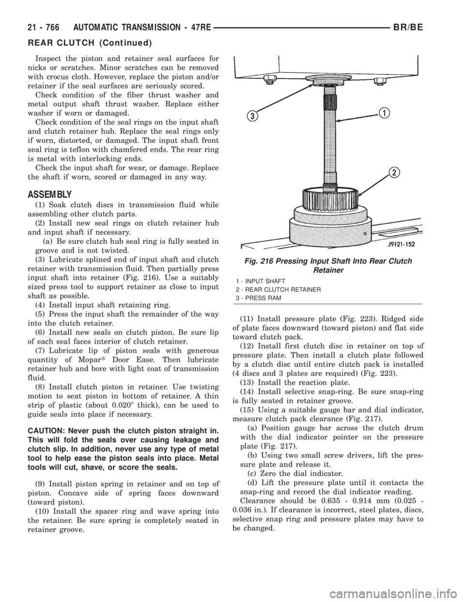
retainer with transmission fluid. Then partially press
input shaft into retainer (Fig. 216). Use a suitably
sized press tool to support retainer as close to input
shaft as possible.
(4) Install input shaft retaining ring.
(5) Press the input shaft the remainder of the way
into the clutch retainer.
(6) Install new seals on clutch piston. Be sure lip
of each seal faces interior of clutch retainer.
(7) Lubricate lip of piston seals with generous
quantity of MopartDoor Ease. Then lubricate
retainer hub and bore with light coat of transmission
fluid.
(8) Install clutch piston in retainer. Use twisting
motion to seat piston in bottom of retainer. A thin
strip of plastic (about 0.0209thick), can be used to
guide seals into place if necessary.
CAUTION: Never push the clutch piston straight in.
This will fold the seals over causing leakage and
clutch slip. In addition, never use any type of metal
tool to help ease the piston seals into place. Metal
tools will cut, shave, or score the seals.
(9) Install piston spring in retainer and on top of
piston. Concave side of spring faces downward
(toward piston).
(10) Install the spacer ring and wave spring into
the retainer. Be sure spring is completely seated in
retainer groove.(11) Install pressure plate (Fig. 223). Ridged side
of plate faces downward (toward piston) and flat side
toward clutch pack.
(12) Install first clutch disc in retainer on top of
pressure plate. Then install a clutch plate followed
by a clutch disc until entire clutch pack is installed
(4 discs and 3 plates are required) (Fig. 223).
(13) Install the reaction plate.
(14) Install selective snap-ring. Be sure snap-ring
is fully seated in retainer groove.
(15) Using a suitable gauge bar and dial indicator,
measure clutch pack clearance (Fig. 217).
(a) Position gauge bar across the clutch drum
with the dial indicator pointer on the pressure
plate (Fig. 217).
(b) Using two small screw drivers, lift the pres-
sure plate and release it.
(c) Zero the dial indicator.
(d) Lift the pressure plate until it contacts the
snap-ring and record the dial indicator reading.
Clearance should be 0.635 - 0.914 mm (0.025 -
0.036 in.). If clearance is incorrect, steel plates, discs,
selective snap ring and pressure plates may have to
be changed.
Fig. 216 Pressing Input Shaft Into Rear Clutch
Retainer
1 - INPUT SHAFT
2 - REAR CLUTCH RETAINER
3 - PRESS RAM
21 - 766 AUTOMATIC TRANSMISSION - 47REBR/BE
REAR CLUTCH (Continued)
Page 2562 of 2889
TIRES/WHEELS
TABLE OF CONTENTS
page page
TIRES/WHEELS
DIAGNOSIS AND TESTING..................1
TIRE AND WHEEL RUNOUT...............1
STANDARD PROCEDURE...................2
TIRE ROTATION.........................2
MATCH MOUNTING......................2
TIRE AND WHEEL BALANCE...............4
TIRES
DESCRIPTION............................5
DIAGNOSIS AND TESTING..................7
PRESSURE GAUGES....................7
TREAD WEAR INDICATORS...............7
TIRE WEAR PATTERNS...................7
TIRE NOISE OR VIBRATION...............8
STANDARD PROCEDURE...................8
REPAIRING LEAKS......................8
SPECIFICATIONS.........................9SPARE TIRE
DESCRIPTION............................9
WHEELS
DESCRIPTION............................9
OPERATION.............................10
DIAGNOSIS AND TESTING.................10
WHEEL INSPECTION....................10
STANDARD PROCEDURE..................10
DUAL WHEEL INSTALLATION.............10
SPECIFICATIONS.........................11
STUDS
REMOVAL..............................12
INSTALLATION...........................12
WHEEL COVER
REMOVAL..............................12
INSTALLATION...........................12
TIRES/WHEELS
DIAGNOSIS AND TESTING - TIRE AND WHEEL
RUNOUT
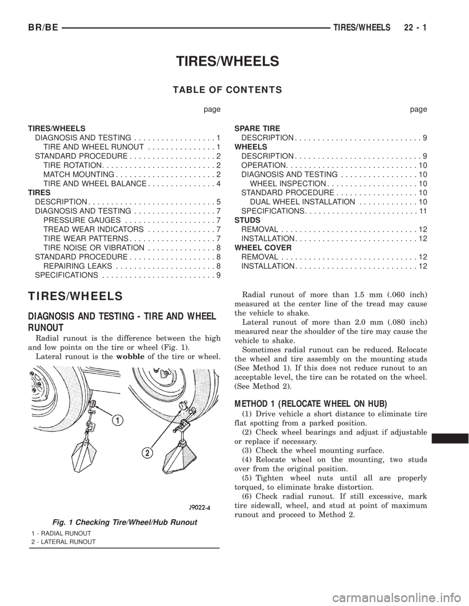
Radial runout is the difference between the high
and low points on the tire or wheel (Fig. 1).
Lateral runout is thewobbleof the tire or wheel.Radial runout of more than 1.5 mm (.060 inch)
measured at the center line of the tread may cause
the vehicle to shake.
Lateral runout of more than 2.0 mm (.080 inch)
measured near the shoulder of the tire may cause the
vehicle to shake.
Sometimes radial runout can be reduced. Relocate
the wheel and tire assembly on the mounting studs
(See Method 1). If this does not reduce runout to an
acceptable level, the tire can be rotated on the wheel.
(See Method 2).
METHOD 1 (RELOCATE WHEEL ON HUB)
(1) Drive vehicle a short distance to eliminate tire
flat spotting from a parked position.
(2) Check wheel bearings and adjust if adjustable
or replace if necessary.
(3) Check the wheel mounting surface.
(4) Relocate wheel on the mounting, two studs
over from the original position.
(5) Tighten wheel nuts until all are properly
torqued, to eliminate brake distortion.
(6) Check radial runout. If still excessive, mark
tire sidewall, wheel, and stud at point of maximum
runout and proceed to Method 2.
Fig. 1 Checking Tire/Wheel/Hub Runout
1 - RADIAL RUNOUT
2 - LATERAL RUNOUT
BR/BETIRES/WHEELS 22 - 1
Page 2567 of 2889
DESCRIPTION
Radial-ply tires improve handling, tread life and
ride quality, and decrease rolling resistance.
Radial-ply tires must always be used in sets of
four. Under no circumstances should they be used on
the front only. They may be mixed with temporary
spare tires when necessary. A maximum speed of 50
MPH is recommended while a temporary spare is in
use.
Radial-ply tires have the same load-carrying capac-
ity as other types of tires of the same size. They also
use the same recommended inflation pressures.
The use of oversized tires, either in the front or
rear of the vehicle, can cause vehicle drive train fail-
ure. This could also cause inaccurate wheel speed
signals when the vehicle is equipped with Anti-Lock
Brakes.
The use of tires from different manufactures on the
same vehicle is NOT recommended. The proper tire
pressure should be maintained on all four tires.
DESCRIPTION
Where speed limits allow the vehicle to be driven
at high speeds, correct tire inflation pressure is very
important. For speeds up to and including 120 km/h
(75 mph), tires must be inflated to the pressures
shown on the tire placard. For continuous speeds inexcess of 120 km/h (75 mph), tires must be inflated
to the maximum pressure specified on the tire side-
wall.
Vehicles loaded to the maximum capacity should
not be driven at continuous speeds above 75 mph
(120 km/h).
For emergency vehicles that are driven at speeds
over 90 mph (144 km/h), special high speed tires
must be used. Consult tire manufacturer for correct
inflation pressure recommendations.
DESCRIPTION
The original equipment tires provide a proper bal-
ance of many characteristics such as:
²Ride
²Noise
²Handling
²Durability
²Tread life
²Traction
²Rolling resistance
²Speed capability
It is recommended that tires equivalent to the orig-
inal equipment tires be used when replacement is
needed.
Failure to use equivalent replacement tires may
adversely affect the safety and handling of the vehi-
cle.
The use of oversize tires may cause interference
with vehicle components. Under extremes of suspen-
sion and steering travel, interference with vehicle
components may cause tire damage.
WARNING: FAILURE TO EQUIP THE VEHICLE WITH
TIRES HAVING ADEQUATE SPEED CAPABILITY
CAN RESULT IN SUDDEN TIRE FAILURE.
DESCRIPTION
Under inflation will cause rapid shoulder wear, tire
flexing, and possible tire failure (Fig. 12) .
Over inflation will cause rapid center wear and
loss of the tire's ability to cushion shocks (Fig. 13) .
Improper inflation can cause:
²Uneven wear patterns
²Reduced tread life
²Reduced fuel economy
²Unsatisfactory ride
²Vehicle drift
For proper tire pressure specification refer to the
Tire Inflation Pressure Chart provided with the vehi-
cles Owners Manual. A Certification Label on the
drivers side door pillar provides the minimum tire
and rim size for the vehicle. The label also list the
cold inflation pressure for these tires at full load
operation
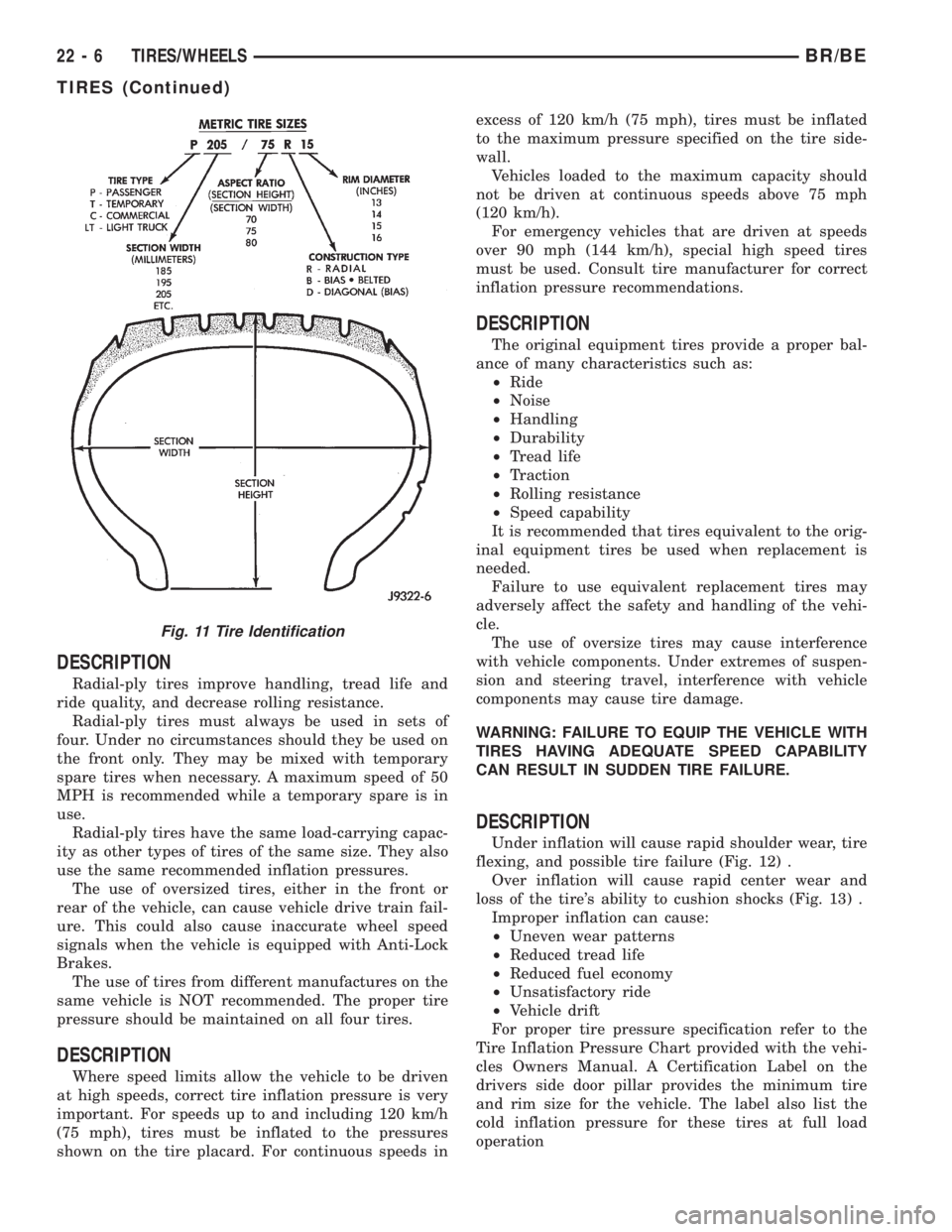
Fig. 11 Tire Identification
22 - 6 TIRES/WHEELSBR/BE
TIRES (Continued)
Page 2568 of 2889

Tire pressures have been chosen to provide safe
operation, vehicle stability, and a smooth ride. Tire
pressure should be checked cold once a month. Tire
pressure decreases as the ambient temperature
drops. Check tire pressure frequently when ambient
temperature varies widely.
Tire inflation pressures are cold inflation pressure.
The vehicle must sit for at least 3 hours to obtain the
correct cold inflation pressure reading. Or be driven
less than one mile after sitting for 3 hours. Tire
inflation pressures may increase from 2 to 6 pounds
per square inch (psi) during operation. Do not reduce
this normal pressure build-up.
WARNING: OVER OR UNDER INFLATED TIRES CAN
AFFECT VEHICLE HANDLING AND TREAD WEAR.
THIS MAY CAUSE THE TIRE TO FAIL SUDDENLY,
RESULTING IN LOSS OF VEHICLE CONTROL.
DIAGNOSIS AND TESTING - PRESSURE
GAUGES
A quality air pressure gauge is recommended to
check tire pressure. After checking the air pressure,
replace valve cap finger tight.
DIAGNOSIS AND TESTING - TREAD WEAR
INDICATORS
Tread wear indicators are molded into the bottom
of the tread grooves. When tread depth is 1.6 mm
(1/16 in.), the tread wear indicators will appear as a
13 mm (1/2 in.) band (Fig. 14).
Tire replacement is necessary when indicators
appear in two or more grooves or if localized balding
occurs.
DIAGNOSIS AND TESTING - TIRE WEAR
PATTERNS
Under inflation will cause wear on the shoulders of
tire. Over inflation will cause wear at the center of
tire.
Excessive camber causes the tire to run at an
angle to the road. One side of tread is then worn
more than the other (Fig. 15).
Excessive toe-in or toe-out causes wear on the
tread edges and a feathered effect across the tread
(Fig. 15).
Fig. 12 Under Inflation Wear
1 - THIN TIRE THREAD AREAS
Fig. 13 Over Inflation Wear
1 - THIN TIRE THREAD AREAFig. 14 Tread Wear Indicators
1 - TREAD ACCEPTABLE
2 - TREAD UNACCEPTABLE
3 - WEAR INDICATOR
BR/BETIRES/WHEELS 22 - 7
TIRES (Continued)
Page 2720 of 2889
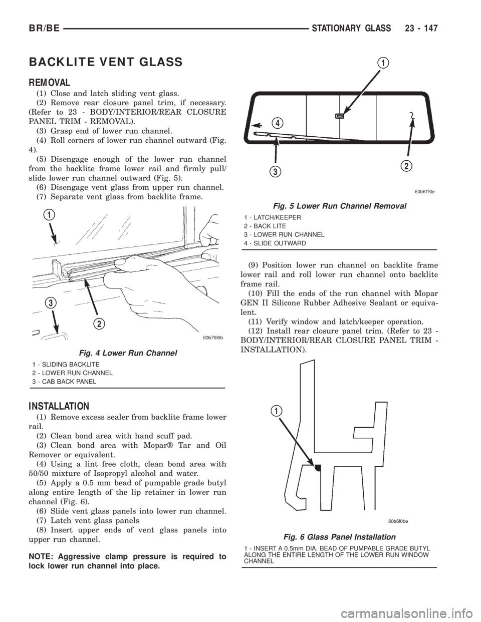
BACKLITE VENT GLASS
REMOVAL
(1) Close and latch sliding vent glass.
(2) Remove rear closure panel trim, if necessary.
(Refer to 23 - BODY/INTERIOR/REAR CLOSURE
PANEL TRIM - REMOVAL).
(3) Grasp end of lower run channel.
(4) Roll corners of lower run channel outward (Fig.
4).
(5) Disengage enough of the lower run channel
from the backlite frame lower rail and firmly pull/
slide lower run channel outward (Fig. 5).
(6) Disengage vent glass from upper run channel.
(7) Separate vent glass from backlite frame.
INSTALLATION
(1) Remove excess sealer from backlite frame lower
rail.
(2) Clean bond area with hand scuff pad.
(3) Clean bond area with Moparž Tar and Oil
Remover or equivalent.
(4) Using a lint free cloth, clean bond area with
50/50 mixture of Isopropyl alcohol and water.
(5) Apply a 0.5 mm bead of pumpable grade butyl
along entire length of the lip retainer in lower run
channel (Fig. 6).
(6) Slide vent glass panels into lower run channel.
(7) Latch vent glass panels
(8) Insert upper ends of vent glass panels into
upper run channel.
NOTE: Aggressive clamp pressure is required to
lock lower run channel into place.(9) Position lower run channel on backlite frame
lower rail and roll lower run channel onto backlite
frame rail.
(10) Fill the ends of the run channel with Mopar
GEN II Silicone Rubber Adhesive Sealant or equiva-
lent.
(11) Verify window and latch/keeper operation.
(12) Install rear closure panel trim. (Refer to 23 -
BODY/INTERIOR/REAR CLOSURE PANEL TRIM -
INSTALLATION).
Fig. 4 Lower Run Channel
1 - SLIDING BACKLITE
2 - LOWER RUN CHANNEL
3 - CAB BACK PANEL
Fig. 5 Lower Run Channel Removal
1 - LATCH/KEEPER
2 - BACK LITE
3 - LOWER RUN CHANNEL
4 - SLIDE OUTWARD
Fig. 6 Glass Panel Installation
1 - INSERT A 0.5mm DIA. BEAD OF PUMPABLE GRADE BUTYL
ALONG THE ENTIRE LENGTH OF THE LOWER RUN WINDOW
CHANNEL
BR/BESTATIONARY GLASS 23 - 147
Page 2771 of 2889
CAUTION:
Liquid refrigerant is corrosive to metal surfaces.
Follow the operating instructions supplied with the
service equipment being used.
Never add R-12 to a refrigerant system designed to
use R-134a. Damage to the system will result.
R-12 refrigerant oil must not be mixed with R-134a
refrigerant oil. They are not compatible.
Do not use R-12 equipment or parts on the R-134a
system. Damage to the system will result.
Do not overcharge the refrigerant system. This will
cause excessive compressor head pressure and
can cause noise and system failure.
Recover the refrigerant before opening any fitting
or connection. Open the fittings with caution, even
after the system has been discharged. Never open
or loosen a connection before recovering the refrig-
erant.
Do not remove the secondary retention clip from
any spring-lock coupler connection while the refrig-
erant system is under pressure. Recover the refrig-
erant before removing the secondary retention clip.
Open the fittings with caution, even after the sys-
tem has been discharged. Never open or loosen a
connection before recovering the refrigerant.
The refrigerant system must always be evacuated
before charging.
Do not open the refrigerant system or uncap a
replacement component until you are ready to ser-
vice the system. This will prevent contamination in
the system.
Before disconnecting a component, clean the out-
side of the fittings thoroughly to prevent contami-
nation from entering the refrigerant system.
Immediately after disconnecting a component from
the refrigerant system, seal the open fittings with a
cap or plug.
Before connecting an open refrigerant fitting,
always install a new seal or gasket. Coat the fitting
and seal with clean refrigerant oil before connect-
ing.
Do not remove the sealing caps from a replacement
component until it is to be installed.
When installing a refrigerant line, avoid sharp
bends that may restrict refrigerant flow. Position the
refrigerant lines away from exhaust system compo-
nents or any sharp edges, which may damage the
line.
Tighten refrigerant fittings only to the specified
torque. The aluminum fittings used in the refriger-
ant system will not tolerate overtightening.
When disconnecting a refrigerant fitting, use a
wrench on both halves of the fitting. This will pre-
vent twisting of the refrigerant lines or tubes.
Refrigerant oil will absorb moisture from the atmo-
sphere if left uncapped. Do not open a container ofrefrigerant oil until you are ready to use it. Replace
the cap on the oil container immediately after using.
Store refrigerant oil only in a clean, airtight, and
moisture-free container.
Keep service tools and the work area clean. Con-
tamination of the refrigerant system through care-
less work habits must be avoided.
CAUTION - REFRIGERANT HOSES/LINES/
TUBES PRECAUTIONS
Kinks or sharp bends in the refrigerant plumbing
will reduce the capacity of the entire system. High
pressures are produced in the system when it is oper-
ating. Extreme care must be exercised to make sure
that all refrigerant system connections are pressure
tight.
A good rule for the flexible hose refrigerant lines is
to keep the radius of all bends at least ten times the
diameter of the hose. Sharp bends will reduce the
flow of refrigerant. The flexible hose lines should be
routed so they are at least 80 millimeters (3 inches)
from the exhaust manifold. It is a good practice to
inspect all flexible refrigerant system hose lines at
least once a year to make sure they are in good con-
dition and properly routed.
There are two types of refrigerant fittings:
²All fittings with O-rings need to be coated with
refrigerant oil before installation. Use only O-rings
that are the correct size and approved for use with
R-134a refrigerant. Failure to do so may result in a
leak.
²Unified plumbing connections with gaskets can-
not be serviced with O-rings. The gaskets are not
reusable and new gaskets do not require lubrication
before installing.
Using the proper tools when making a refrigerant
plumbing connection is very important. Improper
tools or improper use of the tools can damage the
refrigerant fittings. Always use two wrenches when
loosening or tightening tube fittings. Use one wrench
to hold one side of the connection stationary, while
loosening or tightening the other side of the connec-
tion with a second wrench.
The refrigerant must be recovered completely from
the system before opening any fitting or connection.
Open the fittings with caution, even after the refrig-
erant has been recovered. If any pressure is noticed
as a fitting is loosened, tighten the fitting and
recover the refrigerant from the system again.
Do not discharge refrigerant into the atmosphere.
Use an R-134a refrigerant recovery/recycling device
that meets SAE Standard J2210.
24 - 42 PLUMBINGBR/BE
PLUMBING (Continued)
Page 2775 of 2889
STANDARD PROCEDURE - REFRIGERANT
SYSTEM CHARGE
WARNING: REVIEW THE WARNINGS AND CAU-
TIONS IN THE FRONT OF THIS SECTION BEFORE
PERFORMING THE FOLLOWING OPERATION.
(Refer to 24 - HEATING & AIR CONDITIONING/
PLUMBING - WARNING) (Refer to 24 - HEATING &
AIR CONDITIONING/PLUMBING - CAUTION)
After the refrigerant system has been tested for
leaks and evacuated, a refrigerant charge can be
injected into the system. (Refer to 24 - HEATING &
AIR CONDITIONING/PLUMBING - SPECIFICA-
TIONS - CHARGE CAPACITY)
A R-134a refrigerant recovery/recycling/charging
station that meets SAE Standard J2210 must be
used to charge the refrigerant system with R-134a
refrigerant. Refer to the operating instructions sup-
plied by the equipment manufacturer for proper care
and use of this equipment.
SPECIFICATIONS
SPECIFICATIONS
The R-134a refrigerant system charge capacity for
this vehicle is: 0.907 kilograms (32 ounces).
A/C COMPRESSOR
DESCRIPTION - A/C COMPRESSOR
The air conditioning system uses a Sanden
SD7H15 seven cylinder, reciprocating wobble plate-
type compressor on all models. This compressor has a
fixed displacement of 150 cubic centimeters (9.375
cubic inches), and has both the suction and discharge
ports located on the cylinder head. A label identifying
the use of R-134a refrigerant is located on the com-
pressor.
DESCRIPTION - HIGH PRESSURE RELIEF
VALVE
A high pressure relief valve is located on the com-
pressor cylinder head, which is at the rear of the
compressor. This mechanical valve is designed to
vent refrigerant from the system to protect against
damage to the compressor and other system compo-
nents, caused by condenser air flow restriction or an
overcharge of refrigerant.
OPERATION - A/C COMPRESSOR
The compressor is driven by the engine through an
electric clutch, drive pulley and belt arrangement.
The compressor is lubricated by refrigerant oil that iscirculated throughout the refrigerant system with the
refrigerant.
The compressor draws in low-pressure refrigerant
vapor from the evaporator through its suction port. It
then compresses the refrigerant into a high-pressure,
high-temperature refrigerant vapor, which is then
pumped to the condenser through the compressor dis-
charge port.
The compressor cannot be repaired. If faulty or
damaged, the entire compressor assembly must be
replaced. The compressor clutch, pulley and clutch
coil are available for service.
OPERATION - HIGH PRESSURE RELIEF VALVE
The high pressure relief valve vents the system
when a discharge pressure of 3445 to 4135 kPa (500
to 600 psi) or above is reached. The valve closes with
a minimum discharge pressure of 2756 kPa (400 psi)
is reached.
The high pressure relief valve vents only enough
refrigerant to reduce the system pressure, and then
re-seats itself. The majority of the refrigerant is con-
served in the system. If the valve vents refrigerant, it
does not mean the valve is faulty.
The high pressure relief valve is a factory-cali-
brated unit. The valve cannot be adjusted or
repaired, and must not be removed or otherwise dis-
turbed. The valve is only serviced as a part of the
compressor assembly.
DIAGNOSIS AND TESTING - A/C COMPRESSOR
When investigating an air conditioning related
noise, you must first know the conditions under
which the noise occurs. These conditions include:
weather, vehicle speed, transmission in gear or neu-
tral, engine speed, engine temperature, and any
other special conditions. Noises that develop during
air conditioning operation can often be misleading.
For example: What sounds like a failed front bearing
or connecting rod, may be caused by loose bolts, nuts,
mounting brackets, or a loose compressor clutch
assembly.
Drive belts are speed sensitive. At different engine
speeds and depending upon belt tension, belts can
develop noises that are mistaken for a compressor
noise. Improper belt tension can cause a misleading
noise when the compressor clutch is engaged, which
may not occur when the compressor clutch is disen-
gaged. Check the serpentine drive belt condition and
tension as described in Cooling before beginning this
procedure.
(1) Select a quiet area for testing. Duplicate the
complaint conditions as much as possible. Switch the
compressor on and off several times to clearly iden-
tify the compressor noise. Listen to the compressor
while the clutch is engaged and disengaged. Probe
24 - 46 PLUMBINGBR/BE
PLUMBING (Continued)