2001 DODGE RAM wheel
[x] Cancel search: wheelPage 279 of 2889
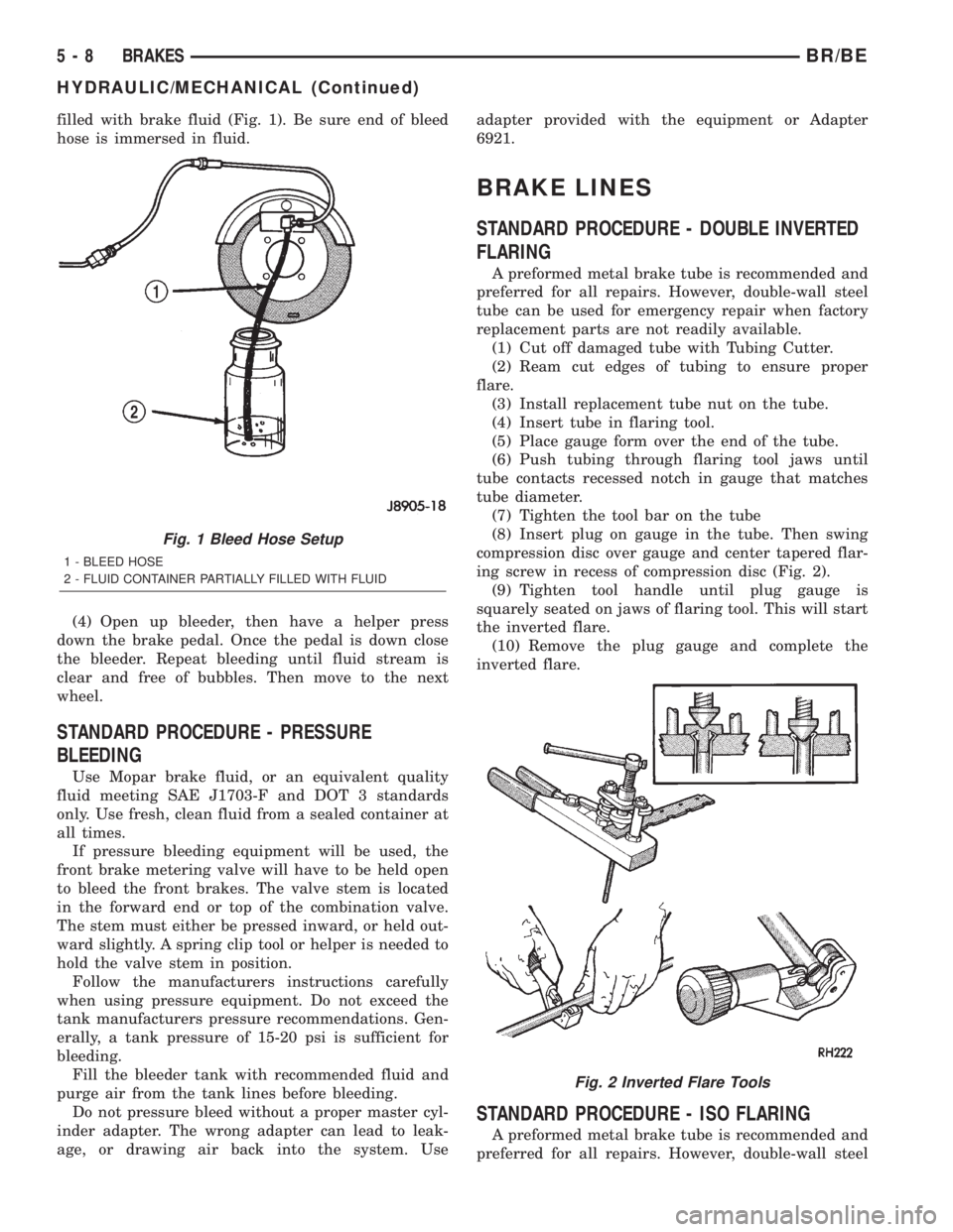
filled with brake fluid (Fig. 1). Be sure end of bleed
hose is immersed in fluid.
(4) Open up bleeder, then have a helper press
down the brake pedal. Once the pedal is down close
the bleeder. Repeat bleeding until fluid stream is
clear and free of bubbles. Then move to the next
wheel.
STANDARD PROCEDURE - PRESSURE
BLEEDING
Use Mopar brake fluid, or an equivalent quality
fluid meeting SAE J1703-F and DOT 3 standards
only. Use fresh, clean fluid from a sealed container at
all times.
If pressure bleeding equipment will be used, the
front brake metering valve will have to be held open
to bleed the front brakes. The valve stem is located
in the forward end or top of the combination valve.
The stem must either be pressed inward, or held out-
ward slightly. A spring clip tool or helper is needed to
hold the valve stem in position.
Follow the manufacturers instructions carefully
when using pressure equipment. Do not exceed the
tank manufacturers pressure recommendations. Gen-
erally, a tank pressure of 15-20 psi is sufficient for
bleeding.
Fill the bleeder tank with recommended fluid and
purge air from the tank lines before bleeding.
Do not pressure bleed without a proper master cyl-
inder adapter. The wrong adapter can lead to leak-
age, or drawing air back into the system. Useadapter provided with the equipment or Adapter
6921.
BRAKE LINES
STANDARD PROCEDURE - DOUBLE INVERTED
FLARING
A preformed metal brake tube is recommended and
preferred for all repairs. However, double-wall steel
tube can be used for emergency repair when factory
replacement parts are not readily available.
(1) Cut off damaged tube with Tubing Cutter.
(2) Ream cut edges of tubing to ensure proper
flare.
(3) Install replacement tube nut on the tube.
(4) Insert tube in flaring tool.
(5) Place gauge form over the end of the tube.
(6) Push tubing through flaring tool jaws until
tube contacts recessed notch in gauge that matches
tube diameter.
(7) Tighten the tool bar on the tube
(8) Insert plug on gauge in the tube. Then swing
compression disc over gauge and center tapered flar-
ing screw in recess of compression disc (Fig. 2).
(9) Tighten tool handle until plug gauge is
squarely seated on jaws of flaring tool. This will start
the inverted flare.
(10) Remove the plug gauge and complete the
inverted flare.
STANDARD PROCEDURE - ISO FLARING
A preformed metal brake tube is recommended and
preferred for all repairs. However, double-wall steel
Fig. 1 Bleed Hose Setup
1 - BLEED HOSE
2 - FLUID CONTAINER PARTIALLY FILLED WITH FLUID
Fig. 2 Inverted Flare Tools
5 - 8 BRAKESBR/BE
HYDRAULIC/MECHANICAL (Continued)
Page 280 of 2889
tube can be used for emergency repair when factory
replacement parts are not readily available.
To make a ISO flare use an ISO flaring tool kit.
(1) Cut off damaged tube with Tubing Cutter.
(2) Remove any burrs from the inside of the tube.
(3) Install tube nut on the tube.
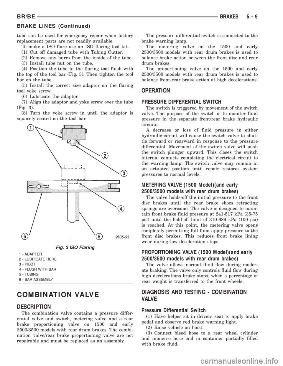
(4) Position the tube in the flaring tool flush with
the top of the tool bar (Fig. 3). Then tighten the tool
bar on the tube.
(5) Install the correct size adaptor on the flaring
tool yoke screw.
(6) Lubricate the adaptor.
(7) Align the adaptor and yoke screw over the tube
(Fig. 3).
(8) Turn the yoke screw in until the adaptor is
squarely seated on the tool bar.
COMBINATION VALVE
DESCRIPTION
The combination valve contains a pressure differ-
ential valve and switch, metering valve and a rear
brake proportioning valve on 1500 and early
2500/3500 models with rear drum brakes. The combi-
nation valve/rear brake proportioning valve are not
repairable and must be replaced as an assembly.The pressure differential switch is connected to the
brake warning lamp.
The metering valve on the 1500 and early
2500/3500 models with rear drum brakes is used to
balance brake action between the front disc and rear
drum brakes.
The proportioning valve on the 1500 and early
2500/3500 models with rear drum brakes is used to
balance front-rear brake action at high decelerations.
OPERATION
PRESSURE DIFFERENTIAL SWITCH
The switch is triggered by movement of the switch
valve. The purpose of the switch is to monitor fluid
pressure in the separate front/rear brake hydraulic
circuits.
A decrease or loss of fluid pressure in either
hydraulic circuit will cause the switch valve to shut-
tle forward or rearward in response to the pressure
differential. Movement of the switch valve will push
the switch plunger upward. This closes the switch
internal contacts completing the electrical circuit to
the warning lamp. The switch valve may remain in
an actuated position until repair restores system
pressures to normal levels.
METERING VALVE (1500 Model)(and early
2500/3500 models with rear drum brakes)
The valve holds-off the initial pressure to the front
disc brakes until the rear brake shoes retracting
springs are overcome. The valve is designed to main-
tain front brake fluid pressure at 241-517 kPa (35-75
psi) until the hold-off limit of 310-689 kPa (100 psi)
is reached. At this point, the metering valve opens
completely permitting full fluid apply pressure to the
front disc brakes. This reduces front brake lining
wear during low deceleration stops.
PROPORTIONING VALVE (1500 Model)(and early
2500/3500 models with rear drum brakes)
The valve allows normal fluid flow during moder-
ate braking. The valve only controls fluid flow during
high decelerations brake stops, when a percentage of
rear weight is transferred to the front wheels.
DIAGNOSIS AND TESTING - COMBINATION
VALVE
Pressure Differential Switch
(1) Have helper sit in drivers seat to apply brake
pedal and observe red brake warning light.
(2) Raise vehicle on hoist.
(3) Connect bleed hose to a rear wheel cylinder
and immerse hose end in container partially filled
with brake fluid.
Fig. 3 ISO Flaring
1 - ADAPTER
2 - LUBRICATE HERE
3 - PILOT
4 - FLUSH WITH BAR
5 - TUBING
6 - BAR ASSEMBLY
BR/BEBRAKES 5 - 9
BRAKE LINES (Continued)
Page 281 of 2889
(4) Have helper press and hold brake pedal to floor
and observe warning light.
(a) If warning light illuminates, switch is operat-
ing correctly.
(b) If light fails to illuminate, check circuit fuse,
bulb, and wiring. The parking brake switch can be
used to aid in identifying whether or not the brake
light bulb and fuse is functional. Repair or replace
parts as necessary and test differential pressure
switch operation again.
(5) If warning light still does not illuminate,
switch is faulty. Replace combination valve assembly,
bleed brake system and verify proper switch and
valve operation.
REMOVAL
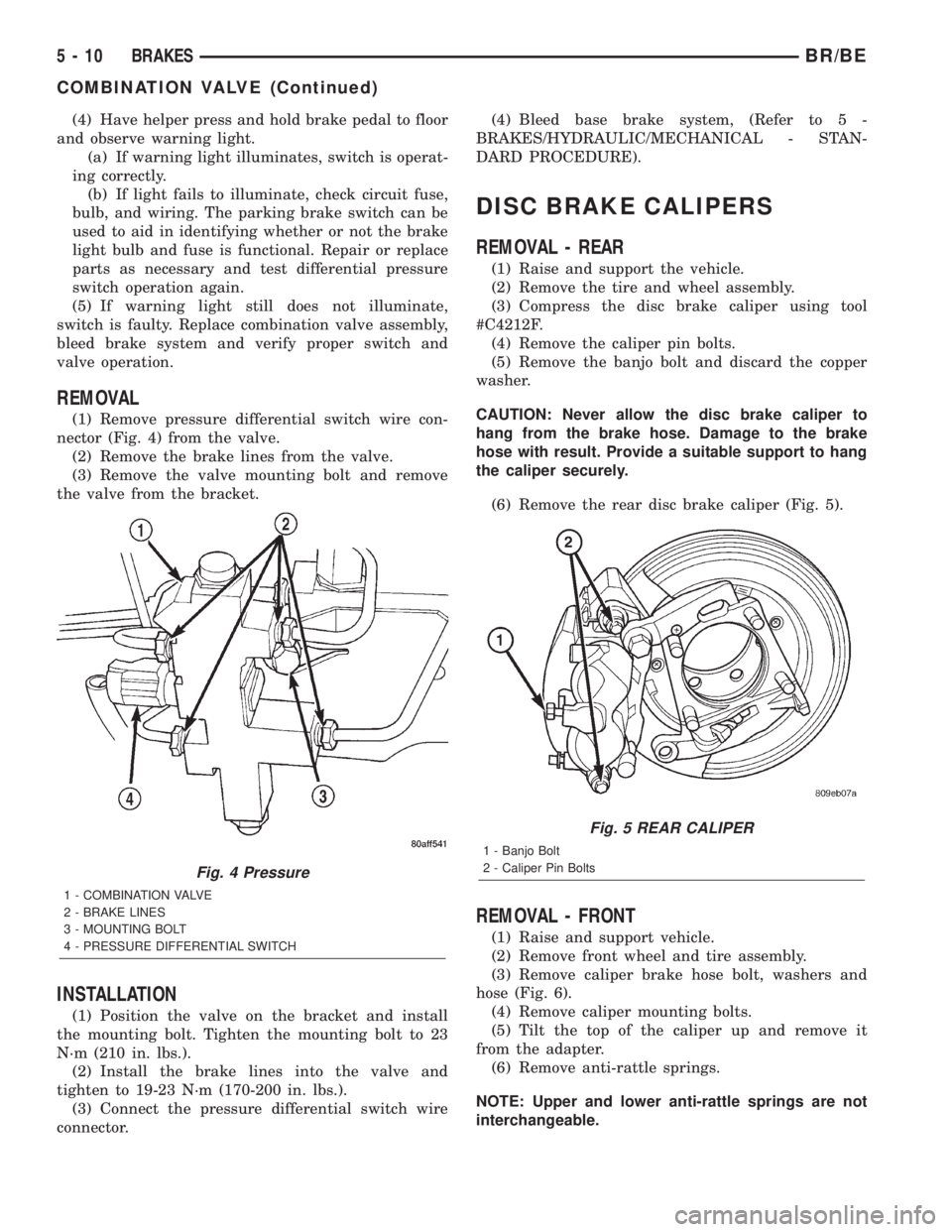
(1) Remove pressure differential switch wire con-
nector (Fig. 4) from the valve.
(2) Remove the brake lines from the valve.
(3) Remove the valve mounting bolt and remove
the valve from the bracket.
INSTALLATION
(1) Position the valve on the bracket and install
the mounting bolt. Tighten the mounting bolt to 23
N´m (210 in. lbs.).
(2) Install the brake lines into the valve and
tighten to 19-23 N´m (170-200 in. lbs.).
(3) Connect the pressure differential switch wire
connector.(4) Bleed base brake system, (Refer to 5 -
BRAKES/HYDRAULIC/MECHANICAL - STAN-
DARD PROCEDURE).
DISC BRAKE CALIPERS
REMOVAL - REAR
(1) Raise and support the vehicle.
(2) Remove the tire and wheel assembly.
(3) Compress the disc brake caliper using tool
#C4212F.
(4) Remove the caliper pin bolts.
(5) Remove the banjo bolt and discard the copper
washer.
CAUTION: Never allow the disc brake caliper to
hang from the brake hose. Damage to the brake
hose with result. Provide a suitable support to hang
the caliper securely.
(6) Remove the rear disc brake caliper (Fig. 5).
REMOVAL - FRONT
(1) Raise and support vehicle.
(2) Remove front wheel and tire assembly.
(3) Remove caliper brake hose bolt, washers and
hose (Fig. 6).
(4) Remove caliper mounting bolts.
(5) Tilt the top of the caliper up and remove it
from the adapter.
(6) Remove anti-rattle springs.
NOTE: Upper and lower anti-rattle springs are not
interchangeable.
Fig. 4 Pressure
1 - COMBINATION VALVE
2 - BRAKE LINES
3 - MOUNTING BOLT
4 - PRESSURE DIFFERENTIAL SWITCH
Fig. 5 REAR CALIPER
1 - Banjo Bolt
2 - Caliper Pin Bolts
5 - 10 BRAKESBR/BE
COMBINATION VALVE (Continued)
Page 285 of 2889
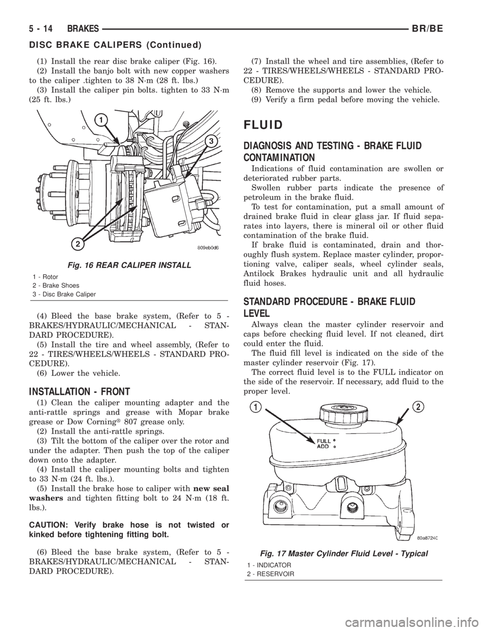
(1) Install the rear disc brake caliper (Fig. 16).
(2) Install the banjo bolt with new copper washers
to the caliper .tighten to 38 N´m (28 ft. lbs.)
(3) Install the caliper pin bolts. tighten to 33 N´m
(25 ft. lbs.)
(4) Bleed the base brake system, (Refer to 5 -
BRAKES/HYDRAULIC/MECHANICAL - STAN-
DARD PROCEDURE).
(5) Install the tire and wheel assembly, (Refer to
22 - TIRES/WHEELS/WHEELS - STANDARD PRO-
CEDURE).
(6) Lower the vehicle.
INSTALLATION - FRONT
(1) Clean the caliper mounting adapter and the
anti-rattle springs and grease with Mopar brake
grease or Dow Corningt807 grease only.
(2) Install the anti-rattle springs.
(3) Tilt the bottom of the caliper over the rotor and
under the adapter. Then push the top of the caliper
down onto the adapter.
(4) Install the caliper mounting bolts and tighten
to 33 N´m (24 ft. lbs.).
(5) Install the brake hose to caliper withnew seal
washersand tighten fitting bolt to 24 N´m (18 ft.
lbs.).
CAUTION: Verify brake hose is not twisted or
kinked before tightening fitting bolt.
(6) Bleed the base brake system, (Refer to 5 -
BRAKES/HYDRAULIC/MECHANICAL - STAN-
DARD PROCEDURE).(7) Install the wheel and tire assemblies, (Refer to
22 - TIRES/WHEELS/WHEELS - STANDARD PRO-
CEDURE).
(8) Remove the supports and lower the vehicle.
(9) Verify a firm pedal before moving the vehicle.
FLUID
DIAGNOSIS AND TESTING - BRAKE FLUID
CONTAMINATION
Indications of fluid contamination are swollen or
deteriorated rubber parts.
Swollen rubber parts indicate the presence of
petroleum in the brake fluid.
To test for contamination, put a small amount of
drained brake fluid in clear glass jar. If fluid sepa-
rates into layers, there is mineral oil or other fluid
contamination of the brake fluid.
If brake fluid is contaminated, drain and thor-
oughly flush system. Replace master cylinder, propor-
tioning valve, caliper seals, wheel cylinder seals,
Antilock Brakes hydraulic unit and all hydraulic
fluid hoses.
STANDARD PROCEDURE - BRAKE FLUID
LEVEL
Always clean the master cylinder reservoir and
caps before checking fluid level. If not cleaned, dirt
could enter the fluid.
The fluid fill level is indicated on the side of the
master cylinder reservoir (Fig. 17).
The correct fluid level is to the FULL indicator on
the side of the reservoir. If necessary, add fluid to the
proper level.
Fig. 16 REAR CALIPER INSTALL
1 - Rotor
2 - Brake Shoes
3 - Disc Brake Caliper
Fig. 17 Master Cylinder Fluid Level - Typical
1 - INDICATOR
2 - RESERVOIR
5 - 14 BRAKESBR/BE
DISC BRAKE CALIPERS (Continued)
Page 288 of 2889
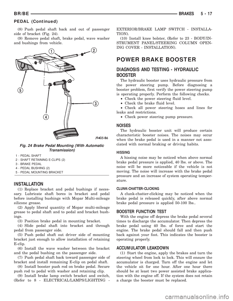
(8) Push pedal shaft back and out of passenger
side of bracket (Fig. 24).
(9) Remove pedal shaft, brake pedal, wave washer
and bushings from vehicle.
INSTALLATION
(1) Replace bracket and pedal bushings if neces-
sary. Lubricate shaft bores in bracket and pedal
before installing bushings with Mopar Multi-mileage
silicone grease.
(2) Apply liberal quantity of Mopar multi-mileage
grease to pedal shaft and to pedal and bracket bush-
ings.
(3) Position brake pedal in mounting bracket.
(4) Slide pedal shaft into bracket and through
pedal from passenger side.
(5) Push pedal shaft out driver side of mounting
bracket just enough to allow installation of retaining
E-clip.
(6) Install the wave washer between the bracket
and the pedal bushing on the passenger side.
(7) Push pedal shaft back toward passenger side of
bracket and install remaining E-clip on pedal shaft.
(8) Install booster push rod on brake pedal. Secure
push rod to pedal with washer and retaining clip.
(9) Install brake lamp switch bracket and switch,
(Refer to 8 - ELECTRICAL/LAMPS/LIGHTING -EXTERIOR/BRAKE LAMP SWITCH - INSTALLA-
TION).
(10) Install knee bolster, (Refer to 23 - BODY/IN-
STRUMENT PANEL/STEERING COLUMN OPEN-
ING COVER - INSTALLATION).
POWER BRAKE BOOSTER
DIAGNOSIS AND TESTING - HYDRAULIC
BOOSTER
The hydraulic booster uses hydraulic pressure from
the power steering pump. Before diagnosing a
booster problem, first verify the power steering pump
is operating properly. Perform the following checks.
²Check the power steering fluid level.
²Check the brake fluid level.
²Check all power steering hoses and lines for
leaks and restrictions.
²Check power steering pump pressure.
NOISES
The hydraulic booster unit will produce certain
characteristic booster noises. The noises may occur
when the brake pedal is used in a manner not asso-
ciated with normal braking or driving habits.
HISSING
A hissing noise may be noticed when above normal
brake pedal pressure is applied, 40 lbs. or above. The
noise will be more noticeable if the vehicle is not
moving. The noise will increase with the brake pedal
pressure and an increase of system operating temper-
ature.
CLUNK-CHATTER-CLICKING
A clunk-chatter-clicking may be noticed when the
brake pedal is released quickly, after above normal
brake pedal pressure is applied 50-100 lbs..
BOOSTER FUNCTION TEST
With the engine off depress the brake pedal several
times to discharge the accumulator. Then depress the
brake pedal using 40 lbs. of force and start the
engine. The brake pedal should fall and then push
back against your foot. This indicates the booster is
operating properly.
ACCUMULATOR LEAKDOWN
(1) Start the engine, apply the brakes and turn the
steering wheel from lock to lock. This will ensure the
accumulator is charged. Turn off the engine and let
the vehicle sit for one hour. After one hour there
should be at least two power assisted brake applica-
tion with the engine off. If the system does not retain
a charge the booster must be replaced.
Fig. 24 Brake Pedal Mounting (With Automatic
Transmission)
1 - PEDAL SHAFT
2 - SHAFT RETAINING E-CLIPS (2)
3 - BRAKE PEDAL
4 - PEDAL BUSHING (2)
5 - PEDAL MOUNTING BRACKET
BR/BEBRAKES 5 - 17
PEDAL (Continued)
Page 290 of 2889
STANDARD PROCEDURE - BLEEDING
The hydraulic booster is generally self-bleeding,
this procedure will normally bleed the air from the
booster. Normal driving and operation of the unit will
remove any remaining trapped air.
(1) Fill power steering pump reservoir.
(2) Disconnect fuel shutdown relay and crank the
engine for several seconds, Refer to Fuel System for
relay location and WARNING.
(3) Check fluid level and add if necessary.
(4) Connect fuel shutdown relay and start the
engine.
(5) Turn the steering wheel slowly from lock to
lock twice.
(6) Stop the engine and discharge the accumulator
by depressing the brake pedal 5 times.
(7) Start the engine and turn the steering wheel
slowly from lock to lock twice.
(8) Turn off the engine and check fluid level and
add if necessary.
NOTE: If fluid foaming occurs, wait for foam to dis-
sipate and repeat steps 7 and 8.
REMOVAL
NOTE: If the booster is being replaced because the
power steering fluid is contaminated, flush the
power steering system before replacing the booster.
(1) With engine off depress the brake pedal 5
times to discharge the accumulator.
(2) Remove brake lines from master cylinder.
(3) Remove mounting nuts from the master cylin-
der.
(4) Remove the bracket from the hydraulic booster
lines and master cylinder mounting studs.
(5) Remove the master cylinder.
(6) Remove the return hose and the two pressure
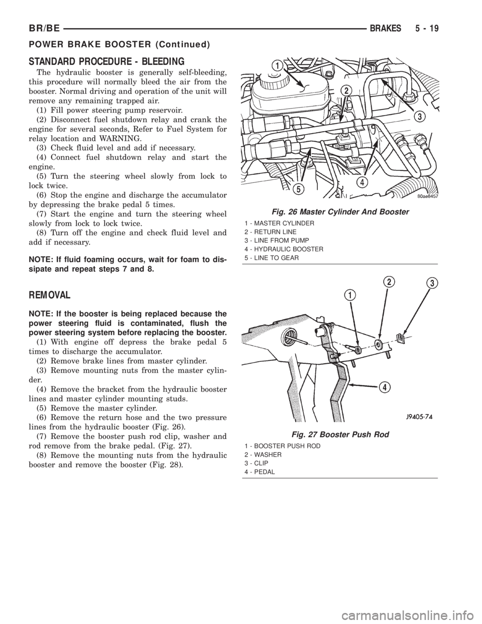
lines from the hydraulic booster (Fig. 26).
(7) Remove the booster push rod clip, washer and
rod remove from the brake pedal. (Fig. 27).
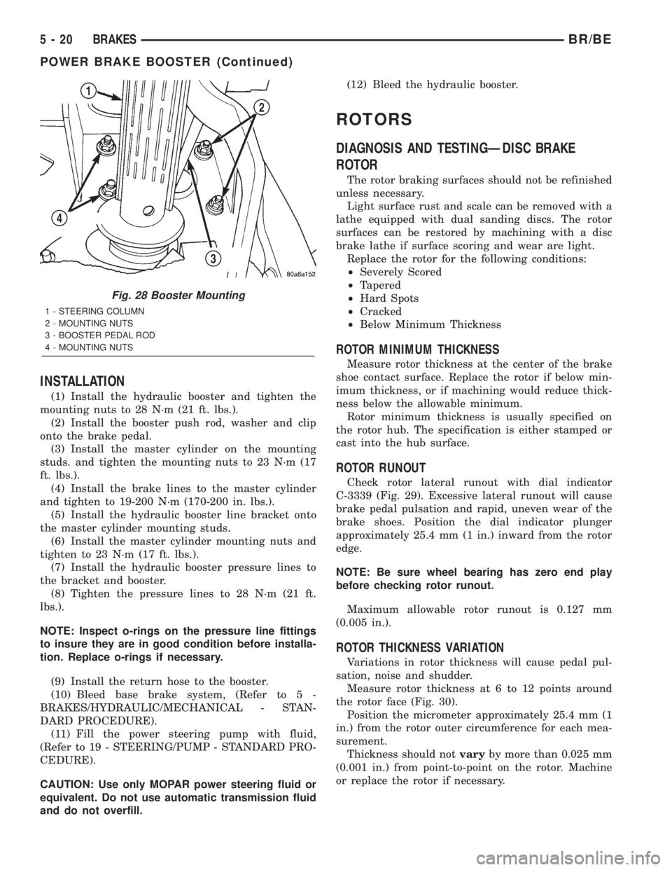
(8) Remove the mounting nuts from the hydraulic
booster and remove the booster (Fig. 28).
Fig. 26 Master Cylinder And Booster
1 - MASTER CYLINDER
2 - RETURN LINE
3 - LINE FROM PUMP
4 - HYDRAULIC BOOSTER
5 - LINE TO GEAR
Fig. 27 Booster Push Rod
1 - BOOSTER PUSH ROD
2 - WASHER
3 - CLIP
4 - PEDAL
BR/BEBRAKES 5 - 19
POWER BRAKE BOOSTER (Continued)
Page 291 of 2889
INSTALLATION
(1) Install the hydraulic booster and tighten the
mounting nuts to 28 N´m (21 ft. lbs.).
(2) Install the booster push rod, washer and clip
onto the brake pedal.
(3) Install the master cylinder on the mounting
studs. and tighten the mounting nuts to 23 N´m (17
ft. lbs.).
(4) Install the brake lines to the master cylinder
and tighten to 19-200 N´m (170-200 in. lbs.).
(5) Install the hydraulic booster line bracket onto
the master cylinder mounting studs.
(6) Install the master cylinder mounting nuts and
tighten to 23 N´m (17 ft. lbs.).
(7) Install the hydraulic booster pressure lines to
the bracket and booster.
(8) Tighten the pressure lines to 28 N´m (21 ft.
lbs.).
NOTE: Inspect o-rings on the pressure line fittings
to insure they are in good condition before installa-
tion. Replace o-rings if necessary.
(9) Install the return hose to the booster.
(10) Bleed base brake system, (Refer to 5 -
BRAKES/HYDRAULIC/MECHANICAL - STAN-
DARD PROCEDURE).
(11) Fill the power steering pump with fluid,
(Refer to 19 - STEERING/PUMP - STANDARD PRO-
CEDURE).
CAUTION: Use only MOPAR power steering fluid or
equivalent. Do not use automatic transmission fluid
and do not overfill.(12) Bleed the hydraulic booster.
ROTORS
DIAGNOSIS AND TESTINGÐDISC BRAKE
ROTOR
The rotor braking surfaces should not be refinished
unless necessary.
Light surface rust and scale can be removed with a
lathe equipped with dual sanding discs. The rotor
surfaces can be restored by machining with a disc
brake lathe if surface scoring and wear are light.
Replace the rotor for the following conditions:
²Severely Scored
²Tapered
²Hard Spots
²Cracked
²Below Minimum Thickness
ROTOR MINIMUM THICKNESS
Measure rotor thickness at the center of the brake
shoe contact surface. Replace the rotor if below min-
imum thickness, or if machining would reduce thick-
ness below the allowable minimum.
Rotor minimum thickness is usually specified on
the rotor hub. The specification is either stamped or
cast into the hub surface.
ROTOR RUNOUT
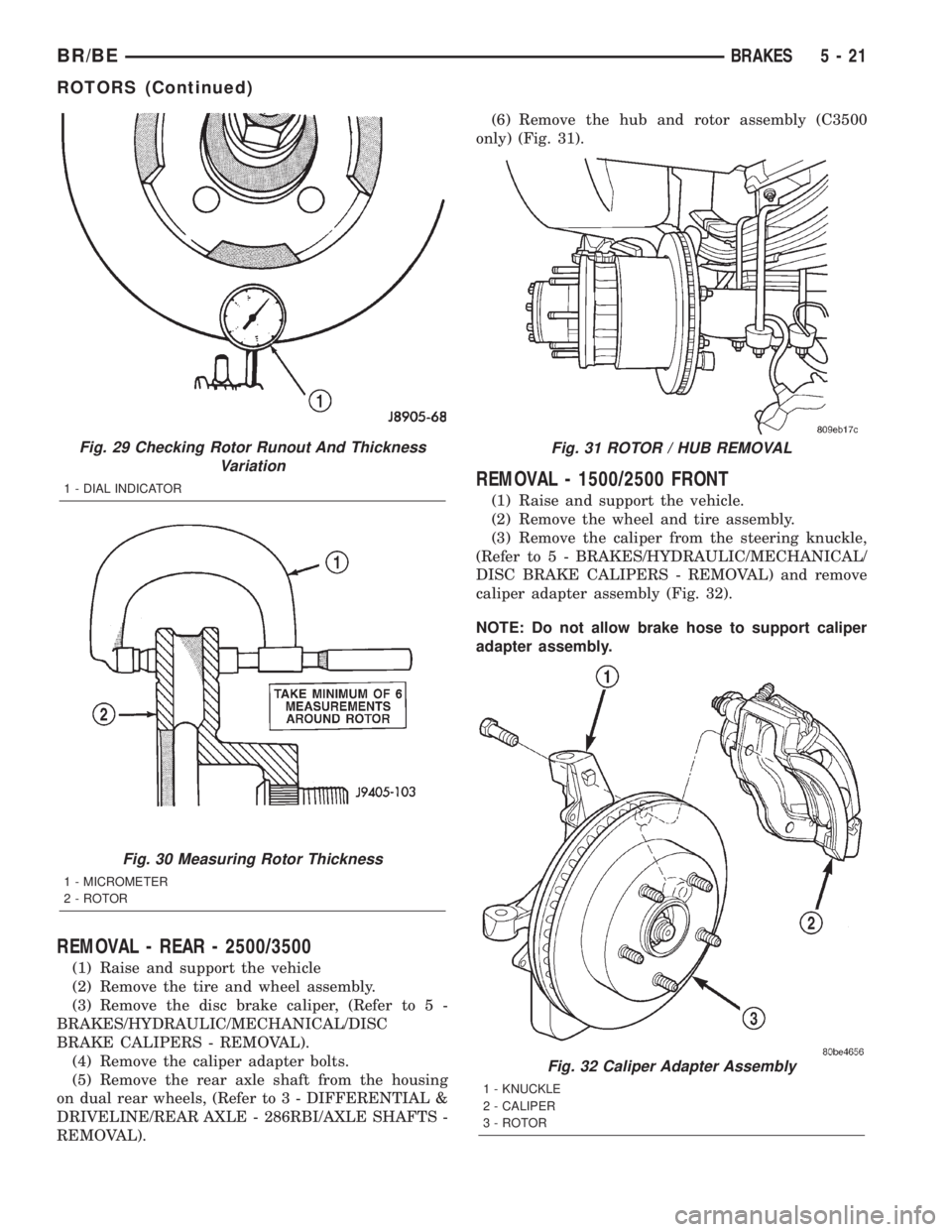
Check rotor lateral runout with dial indicator
C-3339 (Fig. 29). Excessive lateral runout will cause
brake pedal pulsation and rapid, uneven wear of the
brake shoes. Position the dial indicator plunger
approximately 25.4 mm (1 in.) inward from the rotor
edge.
NOTE: Be sure wheel bearing has zero end play
before checking rotor runout.
Maximum allowable rotor runout is 0.127 mm
(0.005 in.).
ROTOR THICKNESS VARIATION
Variations in rotor thickness will cause pedal pul-
sation, noise and shudder.
Measure rotor thickness at 6 to 12 points around
the rotor face (Fig. 30).
Position the micrometer approximately 25.4 mm (1
in.) from the rotor outer circumference for each mea-
surement.
Thickness should notvaryby more than 0.025 mm
(0.001 in.) from point-to-point on the rotor. Machine
or replace the rotor if necessary.
Fig. 28 Booster Mounting
1 - STEERING COLUMN
2 - MOUNTING NUTS
3 - BOOSTER PEDAL ROD
4 - MOUNTING NUTS
5 - 20 BRAKESBR/BE
POWER BRAKE BOOSTER (Continued)
Page 292 of 2889
REMOVAL - REAR - 2500/3500
(1) Raise and support the vehicle
(2) Remove the tire and wheel assembly.
(3) Remove the disc brake caliper, (Refer to 5 -
BRAKES/HYDRAULIC/MECHANICAL/DISC
BRAKE CALIPERS - REMOVAL).
(4) Remove the caliper adapter bolts.
(5) Remove the rear axle shaft from the housing
on dual rear wheels, (Refer to 3 - DIFFERENTIAL &
DRIVELINE/REAR AXLE - 286RBI/AXLE SHAFTS -
REMOVAL).(6) Remove the hub and rotor assembly (C3500
only) (Fig. 31).
REMOVAL - 1500/2500 FRONT
(1) Raise and support the vehicle.
(2) Remove the wheel and tire assembly.
(3) Remove the caliper from the steering knuckle,
(Refer to 5 - BRAKES/HYDRAULIC/MECHANICAL/
DISC BRAKE CALIPERS - REMOVAL) and remove
caliper adapter assembly (Fig. 32).
NOTE: Do not allow brake hose to support caliper
adapter assembly.
Fig. 29 Checking Rotor Runout And Thickness
Variation
1 - DIAL INDICATOR
Fig. 30 Measuring Rotor Thickness
1 - MICROMETER
2 - ROTOR
Fig. 31 ROTOR / HUB REMOVAL
Fig. 32 Caliper Adapter Assembly
1 - KNUCKLE
2 - CALIPER
3 - ROTOR
BR/BEBRAKES 5 - 21
ROTORS (Continued)