2001 DODGE RAM wheel
[x] Cancel search: wheelPage 322 of 2889
INSTALLATION
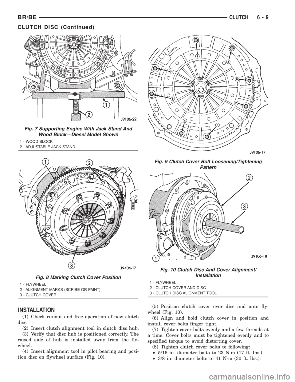
(1) Check runout and free operation of new clutch
disc.
(2) Insert clutch alignment tool in clutch disc hub.
(3) Verify that disc hub is positioned correctly. The
raised side of hub is installed away from the fly-
wheel.
(4) Insert alignment tool in pilot bearing and posi-
tion disc on flywheel surface (Fig. 10).(5) Position clutch cover over disc and onto fly-
wheel (Fig. 10).
(6) Align and hold clutch cover in position and
install cover bolts finger tight.
(7) Tighten cover bolts evenly and a few threads at
a time. Cover bolts must be tightened evenly and to
specified torque to avoid distorting cover.
(8) Tighten clutch cover bolts to following:
²5/16 in. diameter bolts to 23 N´m (17 ft. lbs.).
²3/8 in. diameter bolts to 41 N´m (30 ft. lbs.).
Fig. 7 Supporting Engine With Jack Stand And
Wood BlockÐDiesel Model Shown
1 - WOOD BLOCK
2 - ADJUSTABLE JACK STAND
Fig. 8 Marking Clutch Cover Position
1 - FLYWHEEL
2 - ALIGNMENT MARKS (SCRIBE OR PAINT)
3 - CLUTCH COVER
Fig. 9 Clutch Cover Bolt Loosening/Tightening
Pattern
Fig. 10 Clutch Disc And Cover Alignment/
Installation
1 - FLYWHEEL
2 - CLUTCH COVER AND DISC
3 - CLUTCH DISC ALIGNMENT TOOL
BR/BECLUTCH 6 - 9
CLUTCH DISC (Continued)
Page 324 of 2889
CLUTCH HOUSING
DIAGNOSIS AND TESTING - CLUTCH HOUSING
Clutch housing alignment is important to proper
clutch operation. The housing maintains alignment
between the crankshaft and transmission input
shaft. Misalignment can cause clutch noise, hard
shifting, incomplete release and chatter. It can also
result in premature wear of the pilot bearing, cover
release fingers and clutch disc. In severe cases, mis-
alignment can also cause premature wear of the
transmission input shaft and front bearing.
Housing misalignment is generally caused by
incorrect seating on the engine or transmission, loose
housing bolts, missing alignment dowels, or housing
damage. Infrequently, misalignment may also be
caused by housing mounting surfaces that are not
completely parallel. Misalignment can be corrected
with shims.
CHECKING RUNOUT
Only the NV4500 clutch housing can be
checked using the following bore and face
runout procedures. The NV3500 and NV5600
clutch housings are an integral part of the
transmission and can only be checked off the
vehicle.
MEASURING CLUTCH HOUSING BORE RUNOUT
(1) Remove the clutch housing and strut.
(2) Remove the clutch cover and disc.
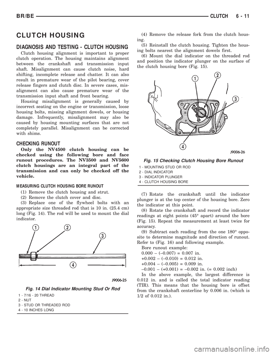
(3) Replace one of the flywheel bolts with an
appropriate size threaded rod that is 10 in. (25.4 cm)
long (Fig. 14). The rod will be used to mount the dial
indicator.(4) Remove the release fork from the clutch hous-
ing.
(5) Reinstall the clutch housing. Tighten the hous-
ing bolts nearest the alignment dowels first.
(6) Mount the dial indicator on the threaded rod
and position the indicator plunger on the surface of
the clutch housing bore (Fig. 15).
(7) Rotate the crankshaft until the indicator
plunger is at the top center of the housing bore. Zero
the indicator at this point.
(8) Rotate the crankshaft and record the indicator
readings at eight points (45É apart) around the bore
(Fig. 15). Repeat the measurement at least twice for
accuracy.
(9) Subtract each reading from the one 180É oppo-
site to determine magnitude and direction of runout.
Refer to (Fig. 16) and following example.
Bore runout example:
0.000 ± (±0.007) = 0.007 in.
+0.002 ± (±0.010) = 0.012 in.
+0.004 ± (±0.005) = 0.009 in.
±0.001 ± (+0.001) = ±0.002 in. (= 0.002 inch)
In the above example, the largest difference is
0.012 in. and is called the total indicator reading
(TIR). This means that the housing bore is offset
from the crankshaft centerline by 0.006 in. (which is
1/2 of 0.012 in.).
Fig. 14 Dial Indicator Mounting Stud Or Rod
1 - 7/16 - 20 THREAD
2 - NUT
3 - STUD OR THREADED ROD
4 - 10 INCHES LONG
Fig. 15 Checking Clutch Housing Bore Runout
1 - MOUNTING STUD OR ROD
2 - DIAL INDICATOR
3 - INDICATOR PLUNGER
4 - CLUTCH HOUSING BORE
BR/BECLUTCH 6 - 11
Page 327 of 2889
(4) Lubricate release fork and pivot contact sur-
faces with MopartHigh Temperature wheel bearing
grease before installation.
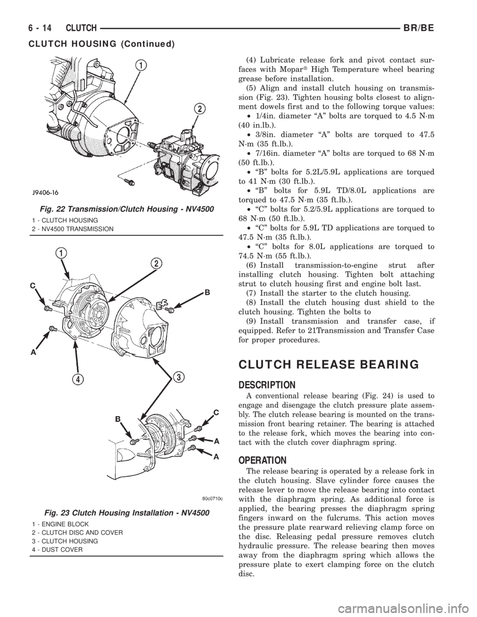
(5) Align and install clutch housing on transmis-
sion (Fig. 23). Tighten housing bolts closest to align-
ment dowels first and to the following torque values:
²1/4in. diameter ªAº bolts are torqued to 4.5 N´m
(40 in.lb.).
²3/8in. diameter ªAº bolts are torqued to 47.5
N´m (35 ft.lb.).
²7/16in. diameter ªAº bolts are torqued to 68 N´m
(50 ft.lb.).
²ªBº bolts for 5.2L/5.9L applications are torqued
to 41 N´m (30 ft.lb.).
²ªBº bolts for 5.9L TD/8.0L applications are
torqued to 47.5 N´m (35 ft.lb.).
²ªCº bolts for 5.2/5.9L applications are torqued to
68 N´m (50 ft.lb.).
²ªCº bolts for 5.9L TD applications are torqued to
47.5 N´m (35 ft.lb.).
²ªCº bolts for 8.0L applications are torqued to
74.5 N´m (55 ft.lb.).
(6) Install transmission-to-engine strut after
installing clutch housing. Tighten bolt attaching
strut to clutch housing first and engine bolt last.
(7) Install the starter to the clutch housing.
(8) Install the clutch housing dust shield to the
clutch housing. Tighten the bolts to
(9) Install transmission and transfer case, if
equipped. Refer to 21Transmission and Transfer Case
for proper procedures.
CLUTCH RELEASE BEARING
DESCRIPTION
A conventional release bearing (Fig. 24) is used to
engage and disengage the clutch pressure plate assem-
bly. The clutch release bearing is mounted on the trans-
mission front bearing retainer. The bearing is attached
to the release fork, which moves the bearing into con-
tact with the clutch cover diaphragm spring.
OPERATION
The release bearing is operated by a release fork in
the clutch housing. Slave cylinder force causes the
release lever to move the release bearing into contact
with the diaphragm spring. As additional force is
applied, the bearing presses the diaphragm spring
fingers inward on the fulcrums. This action moves
the pressure plate rearward relieving clamp force on
the disc. Releasing pedal pressure removes clutch
hydraulic pressure. The release bearing then moves
away from the diaphragm spring which allows the
pressure plate to exert clamping force on the clutch
disc.
Fig. 22 Transmission/Clutch Housing - NV4500
1 - CLUTCH HOUSING
2 - NV4500 TRANSMISSION
Fig. 23 Clutch Housing Installation - NV4500
1 - ENGINE BLOCK
2 - CLUTCH DISC AND COVER
3 - CLUTCH HOUSING
4 - DUST COVER
6 - 14 CLUTCHBR/BE
CLUTCH HOUSING (Continued)
Page 329 of 2889
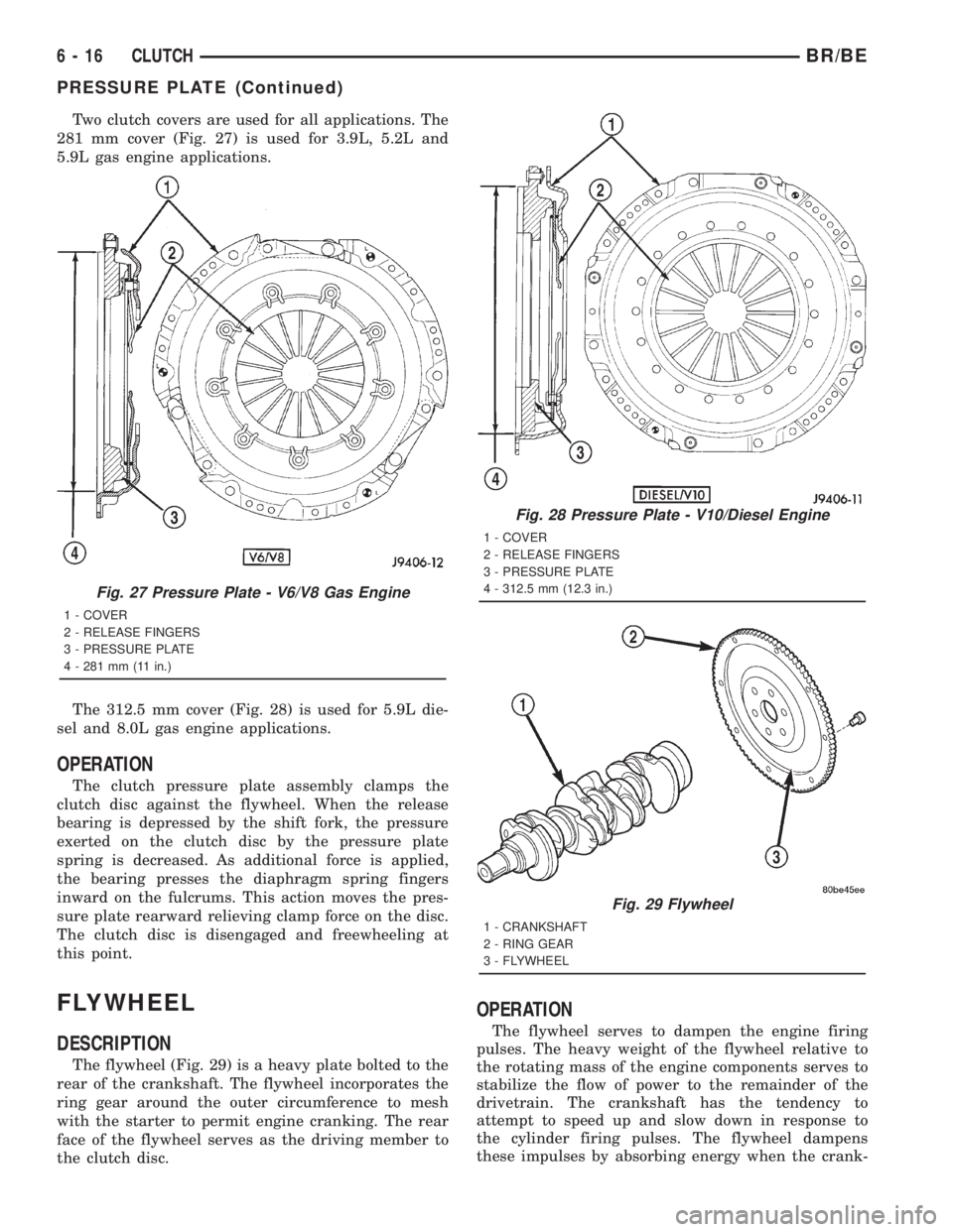
Two clutch covers are used for all applications. The
281 mm cover (Fig. 27) is used for 3.9L, 5.2L and
5.9L gas engine applications.
The 312.5 mm cover (Fig. 28) is used for 5.9L die-
sel and 8.0L gas engine applications.
OPERATION
The clutch pressure plate assembly clamps the
clutch disc against the flywheel. When the release
bearing is depressed by the shift fork, the pressure
exerted on the clutch disc by the pressure plate
spring is decreased. As additional force is applied,
the bearing presses the diaphragm spring fingers
inward on the fulcrums. This action moves the pres-
sure plate rearward relieving clamp force on the disc.
The clutch disc is disengaged and freewheeling at
this point.
FLYWHEEL
DESCRIPTION
The flywheel (Fig. 29) is a heavy plate bolted to the
rear of the crankshaft. The flywheel incorporates the
ring gear around the outer circumference to mesh
with the starter to permit engine cranking. The rear
face of the flywheel serves as the driving member to
the clutch disc.
OPERATION
The flywheel serves to dampen the engine firing
pulses. The heavy weight of the flywheel relative to
the rotating mass of the engine components serves to
stabilize the flow of power to the remainder of the
drivetrain. The crankshaft has the tendency to
attempt to speed up and slow down in response to
the cylinder firing pulses. The flywheel dampens
these impulses by absorbing energy when the crank-
Fig. 27 Pressure Plate - V6/V8 Gas Engine
1 - COVER
2 - RELEASE FINGERS
3 - PRESSURE PLATE
4 - 281 mm (11 in.)
Fig. 28 Pressure Plate - V10/Diesel Engine
1 - COVER
2 - RELEASE FINGERS
3 - PRESSURE PLATE
4 - 312.5 mm (12.3 in.)
Fig. 29 Flywheel
1 - CRANKSHAFT
2 - RING GEAR
3 - FLYWHEEL
6 - 16 CLUTCHBR/BE
PRESSURE PLATE (Continued)
Page 330 of 2889
shaft speeds and releasing the energy back into the
system when the crankshaft slows down.
DIAGNOSIS AND TESTING - FLYWHEEL
Check flywheel runout whenever misalignment is
suspected. Flywheel runout should not exceed 0.08
mm (0.003 in.). Measure runout at the outer edge of
the flywheel face with a dial indicator. Mount the
indicator on a stud installed in place of one of the fly-
wheel bolts.
Common causes of runout are:
²heat warpage
²improper machining
²incorrect bolt tightening
²improper seating on crankshaft flange shoulder
²foreign material on crankshaft flange
Flywheel machining is not recommended. The fly-
wheel clutch surface is machined to a unique contour
and machining will negate this feature. However,
minor flywheel scoring can be cleaned up by hand with
180 grit emery, or with surface grinding equipment.
Remove only enough material to reduce scoring
(approximately 0.001 - 0.003 in.). Heavy stock removal
isnot recommended.
Replace the flywheel if scoring
is severe and deeper than 0.076 mm (0.003 in.).
Excessive stock removal can result in flywheel crack-
ing or warpage after installation; it can also weaken
the flywheel and interfere with proper clutch release.
Clean the crankshaft flange before mounting the
flywheel. Dirt and grease on the flange surface may
cock the flywheel causing excessive runout. Use new
bolts when remounting a flywheel and secure the
bolts with MopartLock And Seal. Tighten flywheel
bolts to specified torque only. Overtightening can dis-
tort the flywheel hub causing runout.
DISASSEMBLY
NOTE: If the teeth are worn or damaged, the fly-
wheel should be replaced as an assembly. This is
the recommended and preferred method of repair.
In cases where a new flywheel is not readily avail-
able, (V10/Diesel Engine only) a replacement ring
gear can be installed. The following procedure must
be observed to avoid damaging the flywheel and
replacement gear.
WARNING: WEAR PROTECTIVE GOGGLES OR
SAFETY GLASSES WHILE CUTTING RING GEAR.
(1) Mark position of the old gear for alignment ref-
erence on the flywheel. Use a scriber for this pur-
pose.
(2) Remove the old gear by cutting most of the way
through it (at one point) with an abrasive cut-off
wheel. Then complete removal with a cold chisel or
punch.
ASSEMBLY
NOTE: The ring gear is a shrink fit on the flywheel.
This means the gear must be expanded by heating
in order to install it. The method of heating and
expanding the gear is extremely important. Every
surface of the gear must be heated at the same
time to produce uniform expansion. An oven or
similar enclosed heating device must be used. Tem-
perature required for uniform expansion is approxi-
mately 375É F.
CAUTION: Do not use an oxy/acetylene torch to
remove the old gear, or to heat and expand a new
gear. The high temperature of the torch flame can
cause localized heating that will damage the fly-
wheel. In addition, using the torch to heat a replace-
ment gear will cause uneven heating and
expansion. The torch flame can also anneal the
gear teeth resulting in rapid wear and damage after
installation.
WARNING: WEAR PROTECTIVE GOGGLES OR
SAFETY GLASSES AND HEAT RESISTENT GLOVES
WHEN HANDLING A HEATED RING GEAR.
(1) The heated gear must be installed evenly to
avoid misalignment or distortion.
(2) Position and install the heated ring gear on the
flywheel with a shop press and a suitable press
plates.
(3) Place flywheel on work bench and let it cool in
normal shop air. Allow the ring gear to cool down
completely before installation it on the engine.
CAUTION: Do not use water or compressed air to
cool the flywheel. The rapid cooling produced by
water or compressed air will distort or crack the
new gear.
PILOT BEARING
DESCRIPTION
Vehicles equipped with a manual transmission uti-
lize a pilot bearing. This bearing is located in the
back of the engine crankshaft. Depending on the type
of engine or application, the pilot bearing can be a
solid soft metallic bushing or a fully caged needle
bearing. The pilot bearing's main functions are to
support the transmission input shaft, maintain
proper alignment of the clutch assembly and allow
the transmission main shaft to rotate at a different
speed than the engine mounted crankshaft.
BR/BECLUTCH 6 - 17
FLYWHEEL (Continued)
Page 391 of 2889
FAN DRIVE VISCOUS CLUTCH
- 3.9L/5.2L/5.9L/8.0L
DESCRIPTION
The thermal viscous fan drive (Fig. 28) is a sili-
cone-fluid- filled coupling used to connect the fan
blades to the water pump shaft. The coupling allows
the fan to be driven in a normal manner. This is
done at low engine speeds while limiting the top
speed of the fan to a predetermined maximum level
at higher engine speeds.
OPERATION
A thermostatic bimetallic spring coil is located on
the front face of the viscous fan drive unit (a typical
viscous unit is shown in (Fig. 29). This spring coil
reacts to the temperature of the radiator discharge
air. It engages the viscous fan drive for higher fan
speed if the air temperature from the radiator rises
above a certain point. Until additional engine cooling
is necessary, the fan will remain at a reduced rpm
regardless of engine speed.
Only when sufficient heat is present, will the vis-
cous fan drive engage. This is when the air flowing
through the radiator core causes a reaction to the
bimetallic coil. It then increases fan speed to provide
the necessary additional engine cooling.
Once the engine has cooled, the radiator discharge
temperature will drop. The bimetallic coil again
reacts and the fan speed is reduced to the previous
disengaged speed.
DIAGNOSIS AND TESTINGÐVISCOUS FAN
DRIVE
NOISE
NOTE: It is normal for fan noise to be louder (roar-
ing) when:
²The underhood temperature is above the engage-
ment point for the viscous drive coupling. This may
occur when ambient (outside air temperature) is very
high.
²Engine loads and temperatures are high such as
when towing a trailer.
²Cool silicone fluid within the fan drive unit is
being redistributed back to its normal disengaged
(warm) position. This can occur during the first 15
seconds to one minute after engine start-up on a cold
engine.
LEAKS
Viscous fan drive operation is not affected by small
oil stains near the drive bearing. If leakage appears
excessive, replace the fan drive unit.
VISCOUS DRIVE
If the fan assembly free-wheels without drag (the
fan blades will revolve more than five turns when
spun by hand), replace the fan drive. This spin test
must be performed when the engine is cool.
For the following test, the cooling system must be
in good condition. It also will ensure against exces-
sively high coolant temperature.
Fig. 28 Viscous Fan
1 - WATER PUMP BYPASS HOSE
2 - FAN BLADE ASSEMBLY
3 - VISCOUS FAN DRIVE
4 - WATER PUMP AND PULLEY
Fig. 29 Viscous Fan DriveÐTypical
1 - VISCOUS FAN DRIVE
2 - THERMOSTATIC SPRING
3 - MOUNTING NUT TO WATER PUMP HUB
7 - 56 ENGINEBR/BE
Page 393 of 2889
Only when sufficient heat is present, will the vis-
cous fan drive engage. This is when the air flowing
through the radiator core causes a reaction to the
bimetallic coil. It then increases fan speed to provide
the necessary additional engine cooling.
Once the engine has cooled, the radiator discharge
temperature will drop. The bimetallic coil again
reacts and the fan speed is reduced to the previous
disengaged speed.
DIAGNOSIS AND TESTINGÐVISCOUS FAN
DRIVE
NOISE
NOTE: It is normal for fan noise to be louder (roar-
ing) when:
²The underhood temperature is above the engage-
ment point for the viscous drive coupling. This may
occur when ambient (outside air temperature) is very
high.
²Engine loads and temperatures are high such as
when towing a trailer.
²Cool silicone fluid within the fan drive unit is
being redistributed back to its normal disengaged
(warm) position. This can occur during the first 15
seconds to one minute after engine start-up on a cold
engine.
LEAKS
Viscous fan drive operation is not affected by small
oil stains near the drive bearing. If leakage appears
excessive, replace the fan drive unit.
VISCOUS DRIVE
If the fan assembly free-wheels without drag (the
fan blades will revolve more than five turns when
spun by hand), replace the fan drive. This spin test
must be performed when the engine is cool.
For the following test, the cooling system must be
in good condition. It also will ensure against exces-
sively high coolant temperature.
WARNING: BE SURE THAT THERE IS ADEQUATE
FAN BLADE CLEARANCE BEFORE DRILLING.
(1) Drill a 3.18-mm (1/8-in) diameter hole in the
top center of the fan shroud.
(2) Obtain a dial thermometer with an 8 inch stem
(or equivalent). It should have a range of -18É-to-
105ÉC (0É-to-220É F). Insert thermometer through the
hole in the shroud. Be sure that there is adequate
clearance from the fan blades.
(3) Connect a tachometer and an engine ignition
timing light. The timing light is to be used as a
strobe light. This step cannot be used on the diesel
engine.
(4) Block the air flow through the radiator. Secure
a sheet of plastic in front of the radiator (or air con-
ditioner condenser). Use tape at the top to secure the
plastic and be sure that the air flow is blocked.
(5) Be sure that the air conditioner (if equipped) is
turned off.
WARNING: USE EXTREME CAUTION WHEN THE
ENGINE IS OPERATING. DO NOT STAND IN A
DIRECT LINE WITH THE FAN. DO NOT PUT YOUR
HANDS NEAR THE PULLEYS, BELTS OR FAN. DO
NOT WEAR LOOSE CLOTHING.
(6) Start the engine and operate at 2400 rpm.
Within ten minutes the air temperature (indicated on
the dial thermometer) should be up to 88É C (190É F).
Fan driveengagementshould start to occur at/be-
tween:
²3.9L/5.2L/5.9L gas engines Ð 79É C (175É F)
²8.0L engine Ð 88É to 96É C (190É to 205É F)
²5.9L diesel engine Ð 71É to 82É C (160É to 179É
F)Engagement is distinguishable by a definite
increasein fan flow noise (roaring). The timing light
also will indicate an increase in the speed of the fan
(non-diesel only).
(7) When viscous drive engagement is verified,
remove the plastic sheet. Fan drivedisengagement
should start to occur at between 57É to 79É C (135É to
175É F). A definitedecreaseof fan flow noise (roar-
ing) should be noticed. If not, replace the defective
viscous fan drive unit.
Fig. 31 Viscous Fan DriveÐTypical
1 - VISCOUS FAN DRIVE
2 - THERMOSTATIC SPRING
3 - MOUNTING NUT TO WATER PUMP HUB
7 - 58 ENGINEBR/BE
FAN DRIVE VISCOUS CLUTCH - 5.9L DIESEL (Continued)
Page 425 of 2889
Refer to Electrical, Restraints for more information
on the clockspring. Refer to Electrical, Body Control/
Central Control Module for more information on the
Central Timer Module. Refer to the appropriate wir-
ing information. The wiring information includes wir-
ing diagrams, proper wire and connector repair
procedures, details of wire harness routing and
retention, connector pin-out information and location
views for the various wire harness connectors, splices
and grounds. Following are general descriptions of
the remaining major components in the standard and
optional factory-installed audio systems.
OPERATION
See the owner's manual in the vehicle glove box for
more information on the features, use and operation
of each of the available audio systems.
CENTRAL TIMER MODULE
The high-line or premium Central Timer Module
(CTM) can also control some features of the audio
system when the vehicle is equipped with the
optional RAZ radio receiver and remote radio
switches. A high-line CTM is used on high-line ver-
sions of this vehicle. A premium CTM is used on
vehicles equipped with the optional heated seats. The
CTM combines the functions of a chime/buzzer mod-
ule, an intermittent wipe module, an illuminated
entry module, a remote keyless entry module, and a
vehicle theft security system module in a single unit.
The high-line or premium CTM also controls and
integrates many of the additional electronic functions
and features included on models with this option.The RAZ radio receiver with a remote radio switch
option is one of the features that the CTM controls.
The CTM is programmed to send switch status mes-
sages over the Chrysler Collision Detection (CCD)
data bus to control the volume, seek, and pre-set sta-
tion advance functions of the RAZ radio receiver. The
CTM monitors the status of the remote radio
switches located on the steering wheel through a
hard wired circuit. The CTM then sends the proper
switch status messages to the radio receiver. The
electronic circuitry within the radio receiver responds
to the switch status messages it receives by adjusting
the radio settings as requested.
Refer to Electrical, Body Control/Central Timer
Module for more information on the high-line CTM.
Refer to Remote Radio Switch in Description and
Operation for more information on this component.
In addition, radio receivers connected to the CCD
data bus have several audio system functions that
can be diagnosed using a DRBIIItscan tool. Refer to
the proper Diagnostic Procedures manual for more
information on DRBIIIttesting of the audio systems.
DIAGNOSIS AND TESTING - AUDIO
WARNING: ON VEHICLES EQUIPPED WITH AIR-
BAGS, REFER TO ELECTRICAL, RESTRAINTS
BEFORE ATTEMPTING ANY STEERING WHEEL,
STEERING COLUMN, OR INSTRUMENT PANEL
COMPONENT DIAGNOSIS OR SERVICE. FAILURE
TO TAKE THE PROPER PRECAUTIONS COULD
RESULT IN ACCIDENTAL AIRBAG DEPLOYMENT
AND POSSIBLE PERSONAL INJURY.
8A - 2 AUDIOBR/BE
AUDIO (Continued)