2001 DODGE RAM wheel
[x] Cancel search: wheelPage 242 of 2889

REAR AXLE - 286RBI
TABLE OF CONTENTS
page page
REAR AXLE - 286RBI
DESCRIPTION..........................169
OPERATION............................169
DIAGNOSIS AND TESTING................171
AXLE...............................171
REMOVAL.............................173
INSTALLATION..........................174
ADJUSTMENTS.........................174
SPECIFICATIONS........................182
SPECIAL TOOLS........................182
AXLE SHAFTS
REMOVAL.............................185
INSTALLATION..........................185
AXLE BEARINGS
REMOVAL.............................185
INSTALLATION..........................185
PINION SEAL
REMOVAL.............................185INSTALLATION..........................185
DIFFERENTIAL
REMOVAL.............................187
DISASSEMBLY..........................188
ASSEMBLY............................188
INSTALLATION..........................188
DIFFERENTIAL - TRAC-LOK
DIAGNOSIS AND TESTING................190
TRAC-LOK...........................190
DISASSEMBLY..........................190
ASSEMBLY............................190
DIFFERENTIAL CASE BEARINGS
REMOVAL.............................192
INSTALLATION..........................192
PINION GEAR/RING GEAR/TONE RING
REMOVAL.............................193
INSTALLATION..........................195
REAR AXLE - 286RBI
DESCRIPTION
The 286 Rear Beam-design Iron (RBI) axle hous-
ings consist of an iron center casting (differential
housing) with axle shaft tubes extending from either
side. The tubes are pressed in to form a one-piece
axle housing.
The integral type housing, hypoid gear design has
the centerline of the pinion set below the centerline
of the ring gear.
The axles are equipped with full-floating axle
shafts, meaning that loads are supported by the axle
housing tubes. The full-float axle shafts are retained
by bolts attached to the hub. The hub rides on two
bearings at the outboard end of the axle tube. The
axle shafts can be removed without disturbing or
removing the wheel bearings. The wheel bearings are
opposed tapered roller bearings and are contained in
the hub assembly.
The removable, stamped steel cover provides a
means for inspection and service without removing
the complete axle from the vehicle. A small, stamped
metal axle gear ratio identification tag is attached to
the housing cover via one of the cover bolts. This tag
also identifies the number of ring and pinion teeth.
The rear wheel anti-lock (RWAL) brake speed sen-
sor is attached to the top, forward exterior of the dif-
ferential housing. A seal is located between thesensor and the wire harness connector. The seal must
be in place when the wire connector is connected to
the sensor. The RWAL brake exciter ring is press-fit-
ted onto the differential case against the ring gear
flange.
The differential case for the standard differential is
a one-piece design. The differential pinion mate shaft
is retained with a roll pin. Differential bearing pre-
load and ring gear backlash are adjusted by the use
of shims located between the differential bearing
cones and case. Pinion bearing preload is set and
maintained by the use of solid shims.
Axles equipped with a Trac-Lokydifferential are
optional for the 286 RBI axle. A Trac-lokydifferen-
tial contains two clutch packs, four pinion gears, and
a one-piece pinion mate cross shaft to provide
increased torque to the non-slipping wheel in addi-
tion to the standard differential components. A Trac-
lokydifferential for the 286 RBI axle has a two-piece
differential case.
OPERATION
STANDARD DIFFERENTIAL
The axle receives power from the transmission/
transfer case through the rear propeller shaft. The
rear propeller shaft is connected to the pinion gear
which rotates the differential through the gear mesh
with the ring gear bolted to the differential case. The
engine power is transmitted to the axle shafts
BR/BEREAR AXLE - 286RBI 3 - 169
Page 243 of 2889
through the pinion mate and side gears. The side
gears are splined to the axle shafts.
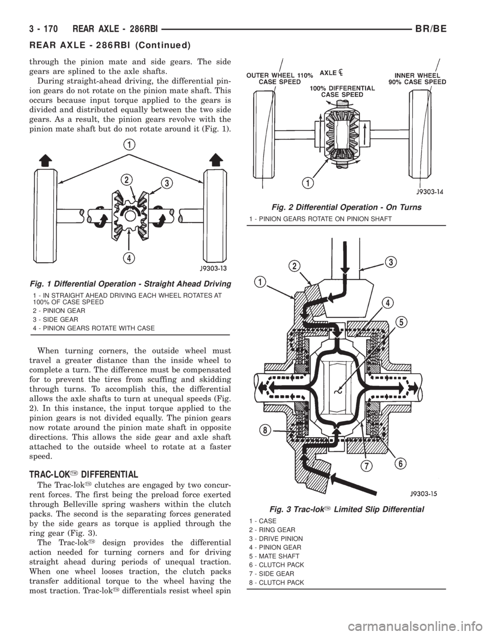
During straight-ahead driving, the differential pin-
ion gears do not rotate on the pinion mate shaft. This
occurs because input torque applied to the gears is
divided and distributed equally between the two side
gears. As a result, the pinion gears revolve with the
pinion mate shaft but do not rotate around it (Fig. 1).
When turning corners, the outside wheel must
travel a greater distance than the inside wheel to
complete a turn. The difference must be compensated
for to prevent the tires from scuffing and skidding
through turns. To accomplish this, the differential
allows the axle shafts to turn at unequal speeds (Fig.
2). In this instance, the input torque applied to the
pinion gears is not divided equally. The pinion gears
now rotate around the pinion mate shaft in opposite
directions. This allows the side gear and axle shaft
attached to the outside wheel to rotate at a faster
speed.
TRAC-LOKYDIFFERENTIAL
The Trac-lokyclutches are engaged by two concur-
rent forces. The first being the preload force exerted
through Belleville spring washers within the clutch
packs. The second is the separating forces generated
by the side gears as torque is applied through the
ring gear (Fig. 3).
The Trac-lokydesign provides the differential
action needed for turning corners and for driving
straight ahead during periods of unequal traction.
When one wheel looses traction, the clutch packs
transfer additional torque to the wheel having the
most traction. Trac-lokydifferentials resist wheel spin
Fig. 1 Differential Operation - Straight Ahead Driving
1 - IN STRAIGHT AHEAD DRIVING EACH WHEEL ROTATES AT
100% OF CASE SPEED
2 - PINION GEAR
3 - SIDE GEAR
4 - PINION GEARS ROTATE WITH CASE
Fig. 2 Differential Operation - On Turns
1 - PINION GEARS ROTATE ON PINION SHAFT
Fig. 3 Trac-lokYLimited Slip Differential
1 - CASE
2 - RING GEAR
3 - DRIVE PINION
4 - PINION GEAR
5 - MATE SHAFT
6 - CLUTCH PACK
7 - SIDE GEAR
8 - CLUTCH PACK
3 - 170 REAR AXLE - 286RBIBR/BE
REAR AXLE - 286RBI (Continued)
Page 244 of 2889
on bumpy roads and provide more pulling power when
one wheel looses traction. Pulling power is provided
continuously until both wheels loose traction. If both
wheels slip due to unequal traction, Trac-lokyopera-
tion is normal. In extreme cases of differences of trac-
tion, the wheel with the least traction may spin.
DIAGNOSIS AND TESTING - AXLE
GEAR NOISE
Axle gear noise can be caused by insufficient lubri-
cant, incorrect backlash, incorrect pinion depth, tooth
contact, worn/damaged gears, or the carrier housing
not having the proper offset and squareness.
Gear noise usually happens at a specific speed
range. The noise can also occur during a specific type
of driving condition. These conditions are accelera-
tion, deceleration, coast, or constant load.
When road testing, first warm-up the axle fluid by
driving the vehicle at least 5 miles and then acceler-
ate the vehicle to the speed range where the noise is
the greatest. Shift out-of-gear and coast through the
peak-noise range. If the noise stops or changes
greatly:
²Check for insufficient lubricant.
²Incorrect ring gear backlash.
²Gear damage.
Differential side gears and pinions can be checked
by turning the vehicle. They usually do not cause
noise during straight-ahead driving when the gears
are unloaded. The side gears are loaded during vehi-
cle turns. A worn pinion shaft can also cause a snap-
ping or a knocking noise.
BEARING NOISE
The axle shaft, differential and pinion bearings can
all produce noise when worn or damaged. Bearing
noise can be either a whining, or a growling sound.
Pinion bearings have a constant-pitch noise. This
noise changes only with vehicle speed. Pinion bearing
noise will be higher pitched because it rotates at a
faster rate. Drive the vehicle and load the differen-
tial. If bearing noise occurs, the rear pinion bearing
is the source of the noise. If the bearing noise is
heard during a coast, the front pinion bearing is the
source.
Worn or damaged differential bearings usually pro-
duce a low pitch noise. Differential bearing noise is
similar to pinion bearing noise. The pitch of differen-
tial bearing noise is also constant and varies only
with vehicle speed.
Axle shaft bearings produce noise and vibration
when worn or damaged. The noise generally changeswhen the bearings are loaded. Road test the vehicle.
Turn the vehicle sharply to the left and to the right.
This will load the bearings and change the noise
level. Where axle bearing damage is slight, the noise
is usually not noticeable at speeds above 30 mph.
LOW SPEED KNOCK
Low speed knock is generally caused by a worn
U-joint or by worn side±gear thrust washers. A worn
pinion shaft bore will also cause low speed knock.
VIBRATION
Vibration at the rear of the vehicle is usually
caused by a:
²Damaged drive shaft.
²Missing drive shaft balance weight(s).
²Worn or out-of-balance wheels.
²Loose wheel lug nuts.
²Worn U-joint(s).
²Loose/broken springs.
²Damaged axle shaft bearing(s).
²Loose pinion gear nut.
²Excessive pinion yoke run out.
²Bent axle shaft(s).
Check for loose or damaged front-end components
or engine/transmission mounts. These components
can contribute to what appears to be a rearend vibra-
tion. Do not overlook engine accessories, brackets
and drive belts.
All driveline components should be examined
before starting any repair.
(Refer to 22 - TIRES/WHEELS - DIAGNOSIS AND
TESTING)
DRIVELINE SNAP
A snap or clunk noise when the vehicle is shifted
into gear (or the clutch engaged), can be caused by:
²High engine idle speed.
²Transmission shift operation.
²Loose engine/transmission/transfer case mounts.
²Worn U-joints.
²Loose spring mounts.
²Loose pinion gear nut and yoke.
²Excessive ring gear backlash.
²Excessive side gear to case clearance.
The source of a snap or a clunk noise can be deter-
mined with the assistance of a helper. Raise the vehi-
cle on a hoist with the wheels free to rotate. Instruct
the helper to shift the transmission into gear. Listen
for the noise, a mechanics stethoscope is helpful in
isolating the source of a noise.
BR/BEREAR AXLE - 286RBI 3 - 171
REAR AXLE - 286RBI (Continued)
Page 245 of 2889
DIAGNOSTIC CHART
Condition Possible Causes Correction
Wheel Noise 1. Wheel loose. 1. Tighten loose nuts.
2. Faulty, brinelled wheel bearing. 2. Replace bearing.
Axle Shaft Noise 1. Misaligned axle tube. 1. Inspect axle tube alignment. Correct
as necessary.
2. Bent or sprung axle shaft. 2. Inspect and correct as necessary.
Axle Shaft Broke 1. Misaligned axle tube. 1. Replace the broken shaft after
correcting tube mis-alignment.
2 Vehicle overloaded. 2. Replace broken shaft and avoid
excessive weight on vehicle.
3. Erratic clutch operation. 3. Replace broken shaft and avoid or
correct erratic clutch operation.
4. Grabbing clutch. 4. Replace broken shaft and inspect and
repair clutch as necessary.
Differential Cracked 1. Improper adjustment of the
differential bearings.1. Replace case and inspect gears and
bearings for further damage. Set
differential bearing pre-load properly.
2. Excessive ring gear backlash. 2. Replace case and inspect gears and
bearings for further damage. Set ring
gear backlash properly.
3. Vehicle overloaded. 3. Replace case and inspect gears and
bearings for further damage. Avoid
excessive vehicle weight.
4. Erratic clutch operation. 4. Replace case and inspect gears and
bearings for further damage. Avoid
erratic use of clutch.
Differential Gears Scored 1. Insufficient lubrication. 1. Replace scored gears. Fill differential
with the correct fluid type and quantity.
2. Improper grade of lubricant. 2. Replace scored gears. Fill differential
with the correct fluid type and quantity.
3. Excessive spinning of one wheel/tire. 3. Replace scored gears. Inspect all
gears, pinion bores, and shaft for
damage. Service as necessary.
Loss Of Lubricant 1. Lubricant level too high. 1. Drain lubricant to the correct level.
2. Worn axle shaft seals. 2. Replace seals.
3. Cracked differential housing. 3. Repair as necessary.
4. Worn pinion seal. 4. Replace seal.
5. Worn/scored yoke. 5. Replace yoke and seal.
6. Axle cover not properly sealed. 6. Remove, clean, and re-seal cover.
3 - 172 REAR AXLE - 286RBIBR/BE
REAR AXLE - 286RBI (Continued)
Page 246 of 2889

Condition Possible Causes Correction
Axle Overheating 1. Lubricant level low. 1. Fill differential to correct level.
2. Improper grade of lubricant. 2. Fill differential with the correct fluid
type and quantity.
3. Bearing pre-loads too high. 3. Re-adjust bearing pre-loads.
4. Insufficient ring gear backlash. 4. Re-adjust ring gear backlash.
Gear Teeth Broke 1. Overloading. 1. Replace gears. Examine other gears
and bearings for possible damage.
2. Erratic clutch operation. 2. Replace gears and examine the
remaining parts for damage. Avoid
erratic clutch operation.
3. Ice-spotted pavement. 3. Replace gears and examine
remaining parts for damage.
4. Improper adjustments. 4. Replace gears and examine
remaining parts for damage. Ensure ring
gear backlash is correct.
Axle Noise 1. Insufficient lubricant. 1. Fill differential with the correct fluid
type and quantity.
2. Improper ring gear and pinion
adjustment.2. Check ring gear and pinion contact
pattern. Adjust backlash or pinion depth.
3. Unmatched ring gear and pinion. 3. Replace gears with a matched ring
gear and pinion.
4. Worn teeth on ring gear and/or
pinion.4. Replace ring gear and pinion.
5. Loose pinion bearings. 5. Adjust pinion bearing pre-load.
6. Loose differential bearings. 6. Adjust differential bearing pre-load.
7. Mis-aligned or sprung ring gear. 7. Measure ring gear run-out. Replace
components as necessary.
8. Loose differential bearing cap bolts. 8. Inspect differential components and
replace as necessary. Ensure that the
bearing caps are torqued tot he proper
specification.
9. Housing not machined properly. 9. Replace housing.
REMOVAL
(1) Raise and support the vehicle.
(2) Position a suitable lifting device under the
axle.
(3) Secure axle to device.
(4) Remove the wheels and tires.
(5) Secure brake drums to the axle shaft.
(6) Remove the RWAL sensor from the differential
housing, if necessary. Refer to 5 Brakes for proce-
dures.
(7) Disconnect the brake hose at the axle junction
block. Do not disconnect the brake hydraulic lines at
the wheel cylinders. Refer to 5 Brakes for procedures.(8) Disconnect the parking brake cables and cable
brackets.
(9) Disconnect the vent hose from the axle shaft
tube.
(10) Mark the propeller shaft and companion
flange for installation alignment reference.
(11) Remove propeller shaft.
(12) Disconnect shock absorbers from axle.
(13) Remove the spring clamps and spring brack-
ets. Refer to 2 Suspension for procedures.
(14) Separate the axle from the vehicle.
BR/BEREAR AXLE - 286RBI 3 - 173
REAR AXLE - 286RBI (Continued)
Page 247 of 2889

INSTALLATION
(1) Raise the axle with lifting device and align to
the leaf spring centering bolts.
(2) Install the spring clamps and spring brackets.
Refer to 2 Suspension for procedures.
(3) Install shock absorbers and tighten nuts to 82
N´m (60 ft. lbs.).
(4) Install the RWAL sensor to the differential
housing, if necessary. Refer to 5 Brakes for proce-
dures.
(5) Connect the parking brake cables and cable
brackets.
(6) Install the brake drums. Refer to 5 Brakes for
procedures.
(7) Connect the brake hose to the axle junction
block. Refer to 5 Brakes for procedures.
(8) Install axle vent hose.
(9) Align propeller shaft and pinion companion
flange reference marks. Install the companion flange
bolts. Tighten to 108 N´m (80 ft. lbs.).
(10) Install the wheels and tires.
(11) Add gear lubricant, if necessary. Refer to
Specifications for lubricant requirements.
(12) Remove lifting device from axle and lower the
vehicle.
ADJUSTMENTS
Ring and pinion gears are supplied as matched
sets only. The identifying numbers for the ring and
pinion gear are etched into the face of each gear (Fig.
4). A plus (+) number, minus (±) number or zero (0) is
etched into the face of the pinion gear. This number
is the amount (in thousandths of an inch) the depth
varies from the standard depth setting of a pinion
etched with a (0). The standard setting from the cen-
ter line of the ring gear to the back face of the pinion
is 147.625 mm (5.812 in.). The standard depth pro-
vides the best teeth contact pattern. Refer to Back-
lash and Contact Pattern Analysis Paragraph in this
section for additional information.
Compensation for pinion depth variance is
achieved with select shims. The shims are placed
under the inner pinion bearing cone (Fig. 5).
If a new gear set is being installed, note the depth
variance etched into both the original and replace-
ment pinion gear. Add or subtract the thickness of
the original depth shims to compensate for the differ-
ence in the depth variances. Refer to the Depth Vari-
ance charts.
Note where Old and New Pinion Marking columns
intersect. Intersecting figure represents plus or
minus amount needed.
Note the etched number on the face of the drive
pinion gear (±1, ±2, 0, +1, +2, etc.). The numbers rep-
resent thousands of an inch deviation from the stan-dard. If the number is negative, add that value to the
required thickness of the depth shim(s). If the num-
ber is positive, subtract that value from the thickness
of the depth shim(s). If the number is 0 no change is
necessary. Refer to the Pinion Gear Depth Variance
Chart.
Fig. 4 Pinion Gear ID Numbers
1 - PRODUCTION NUMBERS
2 - PINION GEAR DEPTH VARIANCE
3 - GEAR MATCHING NUMBER
Fig. 5 Adjustment Shim Locations
1 - PINION BEARING PRELOAD SHIM
2 - DIFFERENTIAL BEARING SHIM
3 - PINION GEAR DEPTH SHIM
3 - 174 REAR AXLE - 286RBIBR/BE
REAR AXLE - 286RBI (Continued)
Page 258 of 2889
AXLE SHAFTS
REMOVAL
(1) Remove the axle shaft flange bolts.
(2) Slide the axle shaft out from the axle tube.
INSTALLATION
(1) Clean the gasket contact surface area on the
flange with an appropriate solvent. Install a new
flange gasket and slide the axle shaft into the tube.
(2) Install the bolts and tighten to 129 N´m (95 ft.
lbs.).
AXLE BEARINGS
REMOVAL
(1) Remove wheel and tire assembly.
(2) Remove brake drum.
(3) Remove the axle shaft.
(4) Remove the lock wedge and adjustment nut.
Use Socket DD-1241±JD to remove the adjustment
nut.
(5) Remove the hub assembly. The outer axle bear-
ing will slide out as the hub is being removed.
(6) Remove inner grease seal and discard. Use
Installer 5064 and Handle C-4171 to drive grease
seal and inner axle bearing from the hub.
(7) Remove the bearing cups from the hub bore.
Use a brass drift, or an appropriate removal tool, to
tap out the cups.
INSTALLATION
(1) Thoroughly clean both axle bearings and inte-
rior of the hub with an appropriate cleaning solvent.
(2) Install the bearing cups. Use Installer 8153
and Handle C-4171 to install the bearing cups.
(3) Apply lubricant to surface area of the bearing
cup.
(4) Install the inner axle bearing in the hub.
(5) Install a new bearing grease seal. Use Installer
8152 and Handle C-4171 to install the grease seal.
(6) Inspect the bearing and seal contact surfaces
on the axle tube spindle for burrs and/or roughness.
Remove all the rough contact surfaces from the axle
spindle. Apply a coating of multi-purpose NLGI,
grade 2, EP-type lubricant to the axle.
CAUTION: Use care to prevent the bearing grease
seal from contacting the axle tube spindle threads
during installation. Otherwise, the seal could be
damaged.
(7) Carefully slide the hub onto the axle.
(8) Install the outer axle bearing.(9) Install the hub bearing adjustment nut. Use
Socket DD-1241±JD to install the adjustment nut.
(10) Tighten the adjustment nut to 163-190 N´m
(120-140 ft. lbs.) while rotating the wheel.
(11) Loosen the adjustment nut 1/8 of-a-turn to
provide 0.001-inch to 0.010-inch wheel bearing end
play.
(12) Tap the locking wedge into the spindle key-
way and adjustment nut. Try to ensure that the lock-
ing wedge is installed into a new position in the
adjustment nut.
(13) Install the axle shaft.
(14) Install the brake drum.
(15) Install the wheel and tire assembly.
PINION SEAL
REMOVAL
(1) Raise and support the vehicle.
(2) Scribe a mark on the universal joint, pinion
yoke, and pinion shaft for reference.
(3) Disconnect the propeller shaft from the pinion
yoke. Secure the propeller shaft in an upright posi-
tion to prevent damage to the rear universal joint.
(4) Remove the wheel and tire assemblies.
(5) Remove the brake drums to prevent any drag.
The drag may cause a false bearing preload torque
measurement.
(6) Rotate the pinion yoke three or four times.
(7) Measure the amount of torque necessary to
rotate the pinion gear with a (in. lbs.) dial-type
torque wrench. Record the torque reading for instal-
lation reference.
(8) Hold the yoke with Wrench 6719. Remove the
pinion shaft nut and washer.
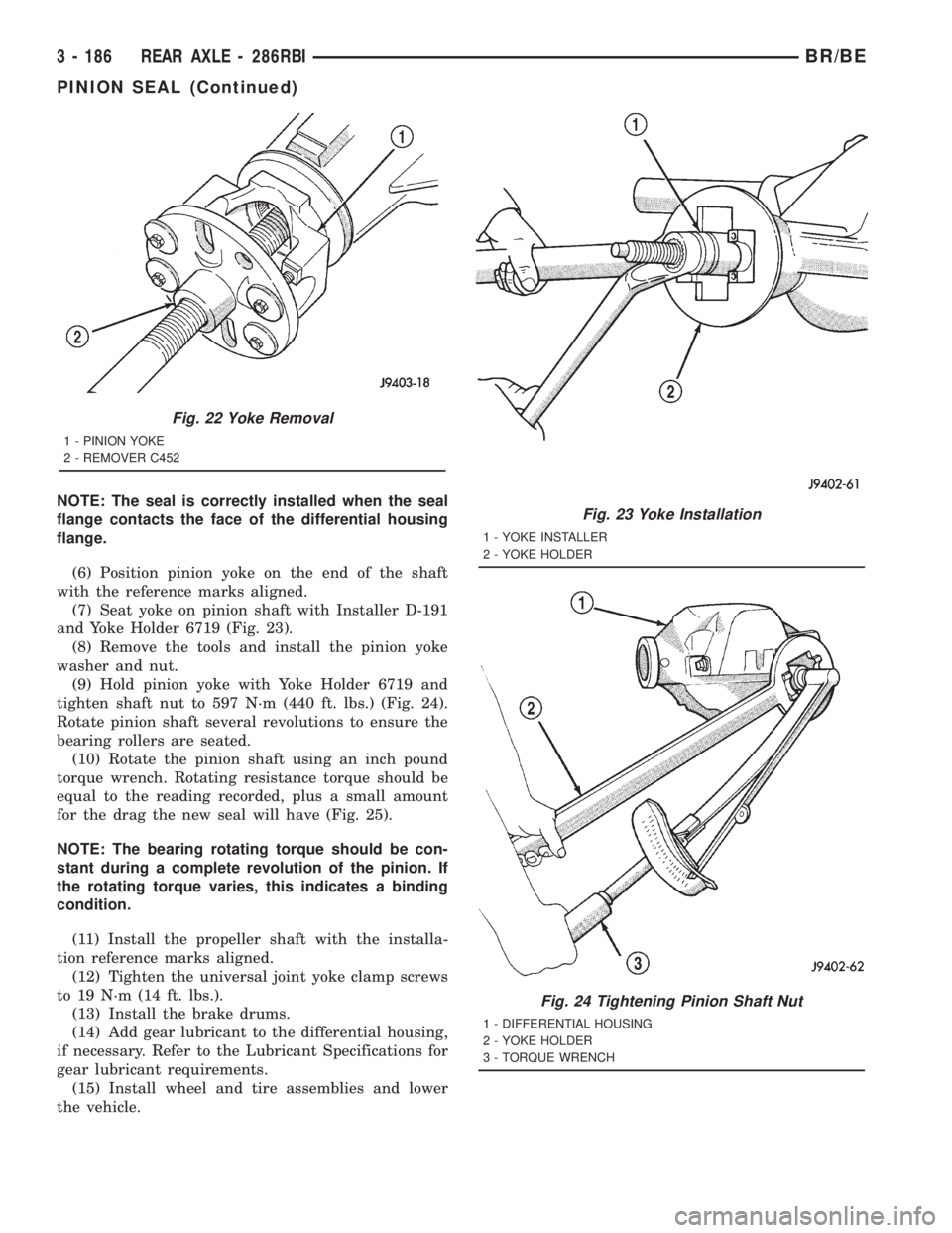
(9) Remove the yoke with Remover C-452 (Fig. 22).
(10) Remove the pinion shaft seal with suitable
pry tool or slide-hammer mounted screw.
INSTALLATION
(1) Clean the seal contact surface in the housing
bore.
(2) Examine the splines on the pinion shaft for
burrs or wear. Remove any burrs and clean the shaft.
(3) Inspect pinion yoke for cracks, worn splines
and worn seal contact surface. Replace yoke if neces-
sary.
NOTE: The outer perimeter of the seal is pre-coated
with a special sealant. An additional application of
sealant is not required.
(4) Apply a light coating of gear lubricant on the
lip of pinion seal.
(5) Install new pinion shaft seal with an appropri-
ate Installer.
BR/BEREAR AXLE - 286RBI 3 - 185
Page 259 of 2889
NOTE: The seal is correctly installed when the seal
flange contacts the face of the differential housing
flange.
(6) Position pinion yoke on the end of the shaft
with the reference marks aligned.
(7) Seat yoke on pinion shaft with Installer D-191
and Yoke Holder 6719 (Fig. 23).
(8) Remove the tools and install the pinion yoke
washer and nut.
(9) Hold pinion yoke with Yoke Holder 6719 and
tighten shaft nut to 597 N´m (440 ft. lbs.) (Fig. 24).
Rotate pinion shaft several revolutions to ensure the
bearing rollers are seated.
(10) Rotate the pinion shaft using an inch pound
torque wrench. Rotating resistance torque should be
equal to the reading recorded, plus a small amount
for the drag the new seal will have (Fig. 25).
NOTE: The bearing rotating torque should be con-
stant during a complete revolution of the pinion. If
the rotating torque varies, this indicates a binding
condition.
(11) Install the propeller shaft with the installa-
tion reference marks aligned.
(12) Tighten the universal joint yoke clamp screws
to 19 N´m (14 ft. lbs.).
(13) Install the brake drums.
(14) Add gear lubricant to the differential housing,
if necessary. Refer to the Lubricant Specifications for
gear lubricant requirements.
(15) Install wheel and tire assemblies and lower
the vehicle.
Fig. 22 Yoke Removal
1 - PINION YOKE
2 - REMOVER C452
Fig. 23 Yoke Installation
1 - YOKE INSTALLER
2 - YOKE HOLDER
Fig. 24 Tightening Pinion Shaft Nut
1 - DIFFERENTIAL HOUSING
2 - YOKE HOLDER
3 - TORQUE WRENCH
3 - 186 REAR AXLE - 286RBIBR/BE
PINION SEAL (Continued)