2001 CHRYSLER VOYAGER display
[x] Cancel search: displayPage 4018 of 4284
Symptom:
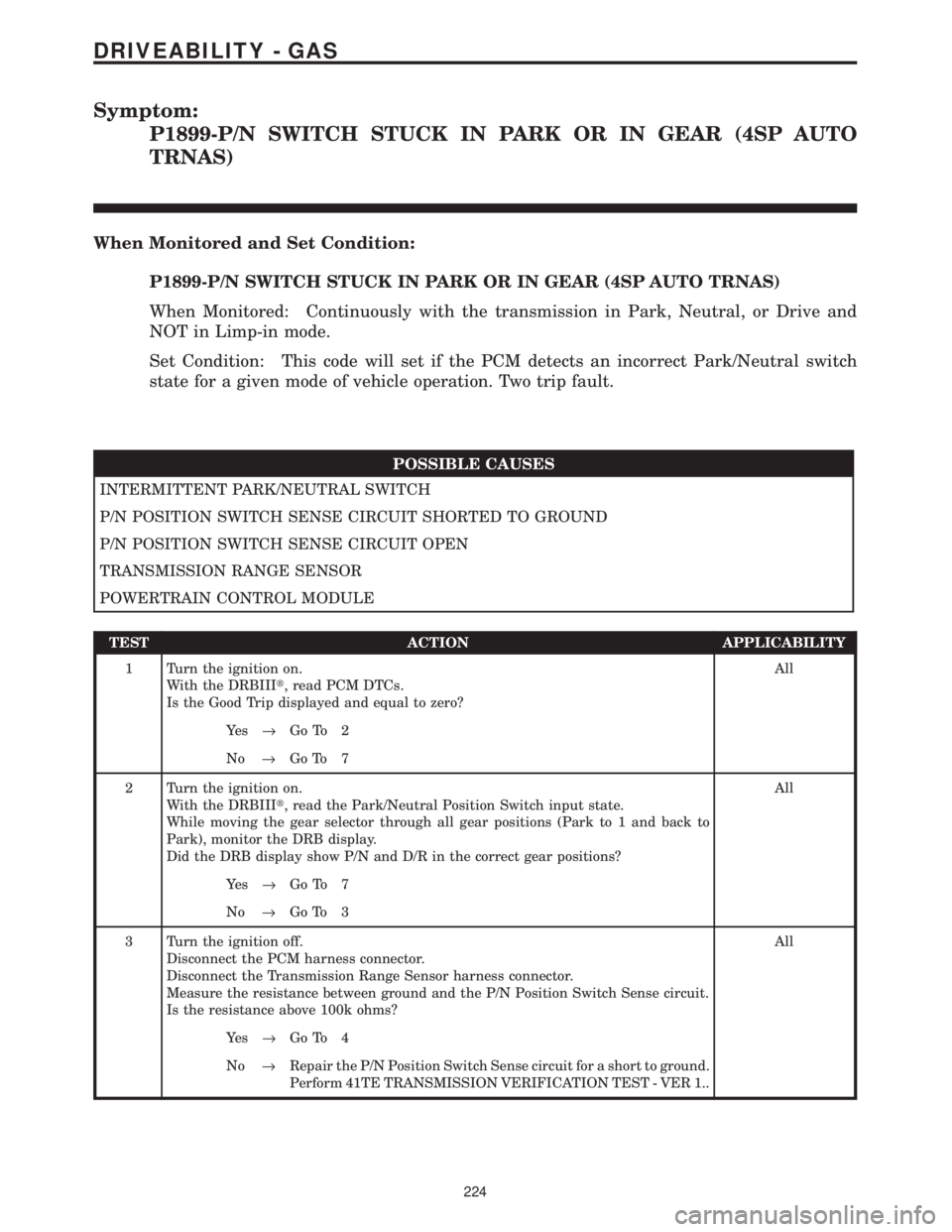
P1899-P/N SWITCH STUCK IN PARK OR IN GEAR (4SP AUTO
TRNAS)
When Monitored and Set Condition:
P1899-P/N SWITCH STUCK IN PARK OR IN GEAR (4SP AUTO TRNAS)
When Monitored: Continuously with the transmission in Park, Neutral, or Drive and
NOT in Limp-in mode.
Set Condition: This code will set if the PCM detects an incorrect Park/Neutral switch
state for a given mode of vehicle operation. Two trip fault.
POSSIBLE CAUSES
INTERMITTENT PARK/NEUTRAL SWITCH
P/N POSITION SWITCH SENSE CIRCUIT SHORTED TO GROUND
P/N POSITION SWITCH SENSE CIRCUIT OPEN
TRANSMISSION RANGE SENSOR
POWERTRAIN CONTROL MODULE
TEST ACTION APPLICABILITY
1 Turn the ignition on.
With the DRBIIIt, read PCM DTCs.
Is the Good Trip displayed and equal to zero?All
Ye s®Go To 2
No®Go To 7
2 Turn the ignition on.
With the DRBIIIt, read the Park/Neutral Position Switch input state.
While moving the gear selector through all gear positions (Park to 1 and back to
Park), monitor the DRB display.
Did the DRB display show P/N and D/R in the correct gear positions?All
Ye s®Go To 7
No®Go To 3
3 Turn the ignition off.
Disconnect the PCM harness connector.
Disconnect the Transmission Range Sensor harness connector.
Measure the resistance between ground and the P/N Position Switch Sense circuit.
Is the resistance above 100k ohms?All
Ye s®Go To 4
No®Repair the P/N Position Switch Sense circuit for a short to ground.
Perform 41TE TRANSMISSION VERIFICATION TEST - VER 1..
224
DRIVEABILITY - GAS
Page 4062 of 4284
Symptom List:
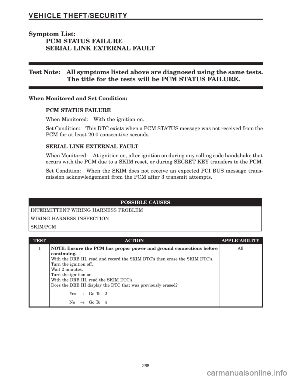
PCM STATUS FAILURE
SERIAL LINK EXTERNAL FAULT
Test Note: All symptoms listed above are diagnosed using the same tests.
The title for the tests will be PCM STATUS FAILURE.
When Monitored and Set Condition:
PCM STATUS FAILURE
When Monitored: With the ignition on.
Set Condition: This DTC exists when a PCM STATUS message was not received from the
PCM for at least 20.0 consecutive seconds.
SERIAL LINK EXTERNAL FAULT
When Monitored: At ignition on, after ignition on during any rolling code handshake that
occurs with the PCM due to a SKIM reset, or during SECRET KEY transfers to the PCM.
Set Condition: When the SKIM does not receive an expected PCI BUS message trans-
mission acknowledgement from the PCM after 3 transmit attempts.
POSSIBLE CAUSES
INTERMITTENT WIRING HARNESS PROBLEM
WIRING HARNESS INSPECTION
SKIM/PCM
TEST ACTION APPLICABILITY
1NOTE: Ensure the PCM has proper power and ground connections before
continuing.
With the DRB III, read and record the SKIM DTC's then erase the SKIM DTC's.
Turn the ignition off.
Wait 2 minutes.
Turn the ignition on.
With the DRB III, read the SKIM DTC's.
Does the DRB III display the DTC that was previously erased?All
Ye s®Go To 2
No®Go To 4
268
VEHICLE THEFT/SECURITY
Page 4063 of 4284
TEST ACTION APPLICABILITY
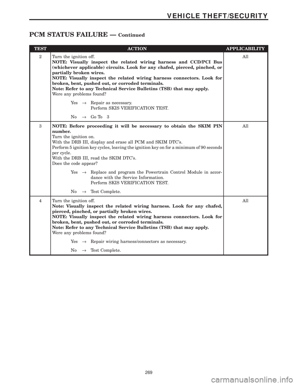
2 Turn the ignition off.
NOTE: Visually inspect the related wiring harness and CCD/PCI Bus
(whichever applicable) circuits. Look for any chafed, pierced, pinched, or
partially broken wires.
NOTE: Visually inspect the related wiring harness connectors. Look for
broken, bent, pushed out, or corroded terminals.
Note: Refer to any Technical Service Bulletins (TSB) that may apply.
Were any problems found?All
Ye s®Repair as necessary.
Perform SKIS VERIFICATION TEST.
No®Go To 3
3NOTE: Before proceeding it will be necessary to obtain the SKIM PIN
number.
Turn the ignition on.
With the DRB III, display and erase all PCM and SKIM DTC's.
Perform 5 ignition key cycles, leaving the ignition key on for a minimum of 90 seconds
per cycle.
With the DRB III, read the SKIM DTC's.
Does the code appear?All
Ye s®Replace and program the Powertrain Control Module in accor-
dance with the Service Information.
Perform SKIS VERIFICATION TEST.
No®Test Complete.
4 Turn the ignition off.
Note: Visually inspect the related wiring harness. Look for any chafed,
pierced, pinched, or partially broken wires.
NOTE: Visually inspect the related wiring harness connectors. Look for
broken, bent, pushed out, or corroded terminals.
Note: Refer to any Technical Service Bulletins (TSB) that may apply.
Were any problems found?All
Ye s®Repair wiring harness/connectors as necessary.
No®Test Complete.
269
VEHICLE THEFT/SECURITY
PCM STATUS FAILURE ÐContinued
Page 4064 of 4284
Symptom:
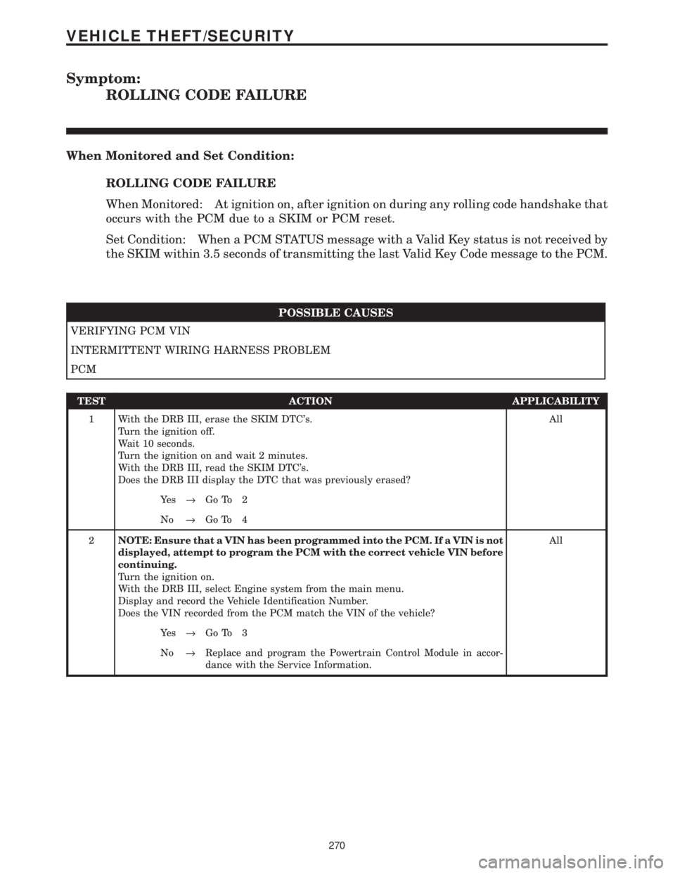
ROLLING CODE FAILURE
When Monitored and Set Condition:
ROLLING CODE FAILURE
When Monitored: At ignition on, after ignition on during any rolling code handshake that
occurs with the PCM due to a SKIM or PCM reset.
Set Condition: When a PCM STATUS message with a Valid Key status is not received by
the SKIM within 3.5 seconds of transmitting the last Valid Key Code message to the PCM.
POSSIBLE CAUSES
VERIFYING PCM VIN
INTERMITTENT WIRING HARNESS PROBLEM
PCM
TEST ACTION APPLICABILITY
1 With the DRB III, erase the SKIM DTC's.
Turn the ignition off.
Wait 10 seconds.
Turn the ignition on and wait 2 minutes.
With the DRB III, read the SKIM DTC's.
Does the DRB III display the DTC that was previously erased?All
Ye s®Go To 2
No®Go To 4
2NOTE: Ensure that a VIN has been programmed into the PCM. If a VIN is not
displayed, attempt to program the PCM with the correct vehicle VIN before
continuing.
Turn the ignition on.
With the DRB III, select Engine system from the main menu.
Display and record the Vehicle Identification Number.
Does the VIN recorded from the PCM match the VIN of the vehicle?All
Ye s®Go To 3
No®Replace and program the Powertrain Control Module in accor-
dance with the Service Information.
270
VEHICLE THEFT/SECURITY
Page 4065 of 4284
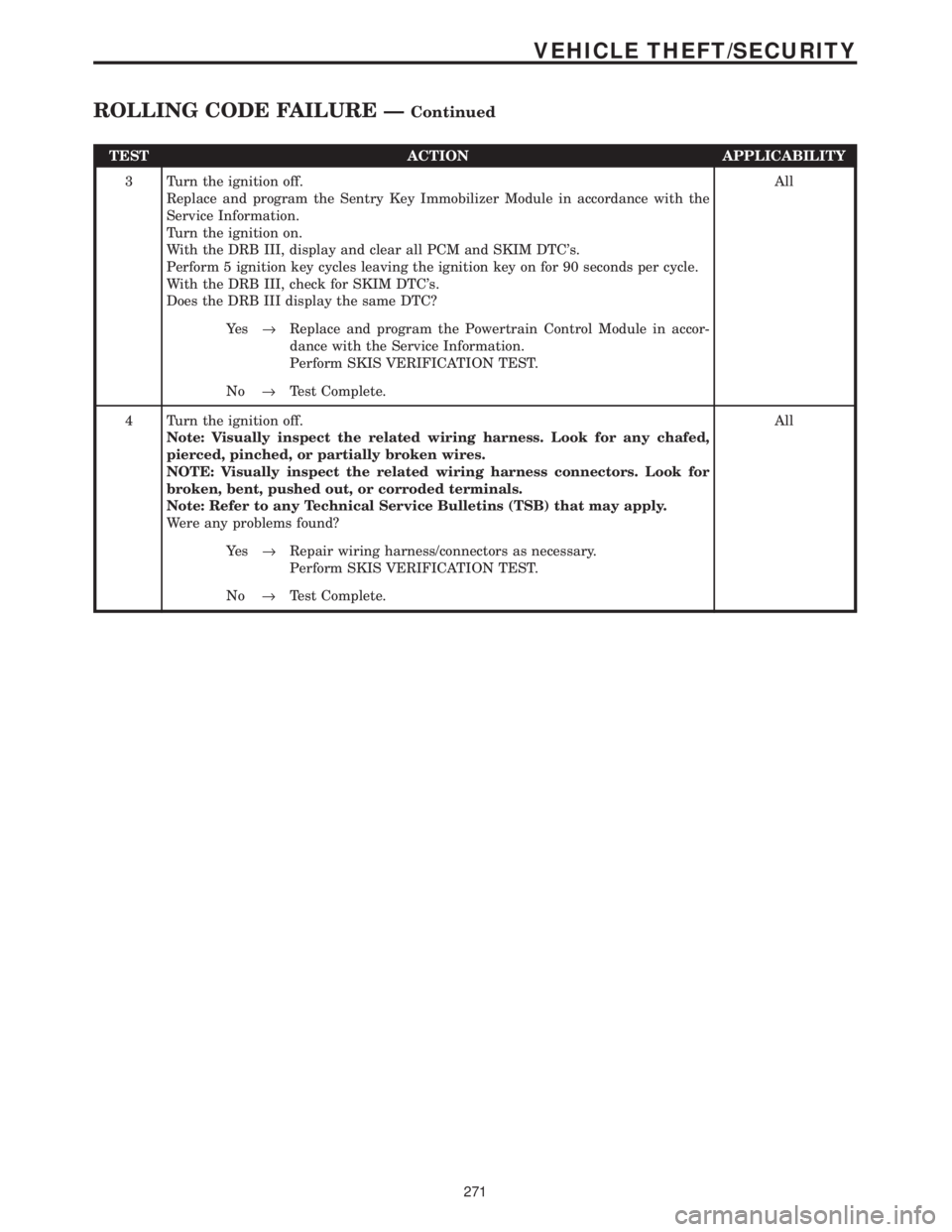
TEST ACTION APPLICABILITY
3 Turn the ignition off.
Replace and program the Sentry Key Immobilizer Module in accordance with the
Service Information.
Turn the ignition on.
With the DRB III, display and clear all PCM and SKIM DTC's.
Perform 5 ignition key cycles leaving the ignition key on for 90 seconds per cycle.
With the DRB III, check for SKIM DTC's.
Does the DRB III display the same DTC?All
Ye s®Replace and program the Powertrain Control Module in accor-
dance with the Service Information.
Perform SKIS VERIFICATION TEST.
No®Test Complete.
4 Turn the ignition off.
Note: Visually inspect the related wiring harness. Look for any chafed,
pierced, pinched, or partially broken wires.
NOTE: Visually inspect the related wiring harness connectors. Look for
broken, bent, pushed out, or corroded terminals.
Note: Refer to any Technical Service Bulletins (TSB) that may apply.
Were any problems found?All
Ye s®Repair wiring harness/connectors as necessary.
Perform SKIS VERIFICATION TEST.
No®Test Complete.
271
VEHICLE THEFT/SECURITY
ROLLING CODE FAILURE ÐContinued
Page 4067 of 4284
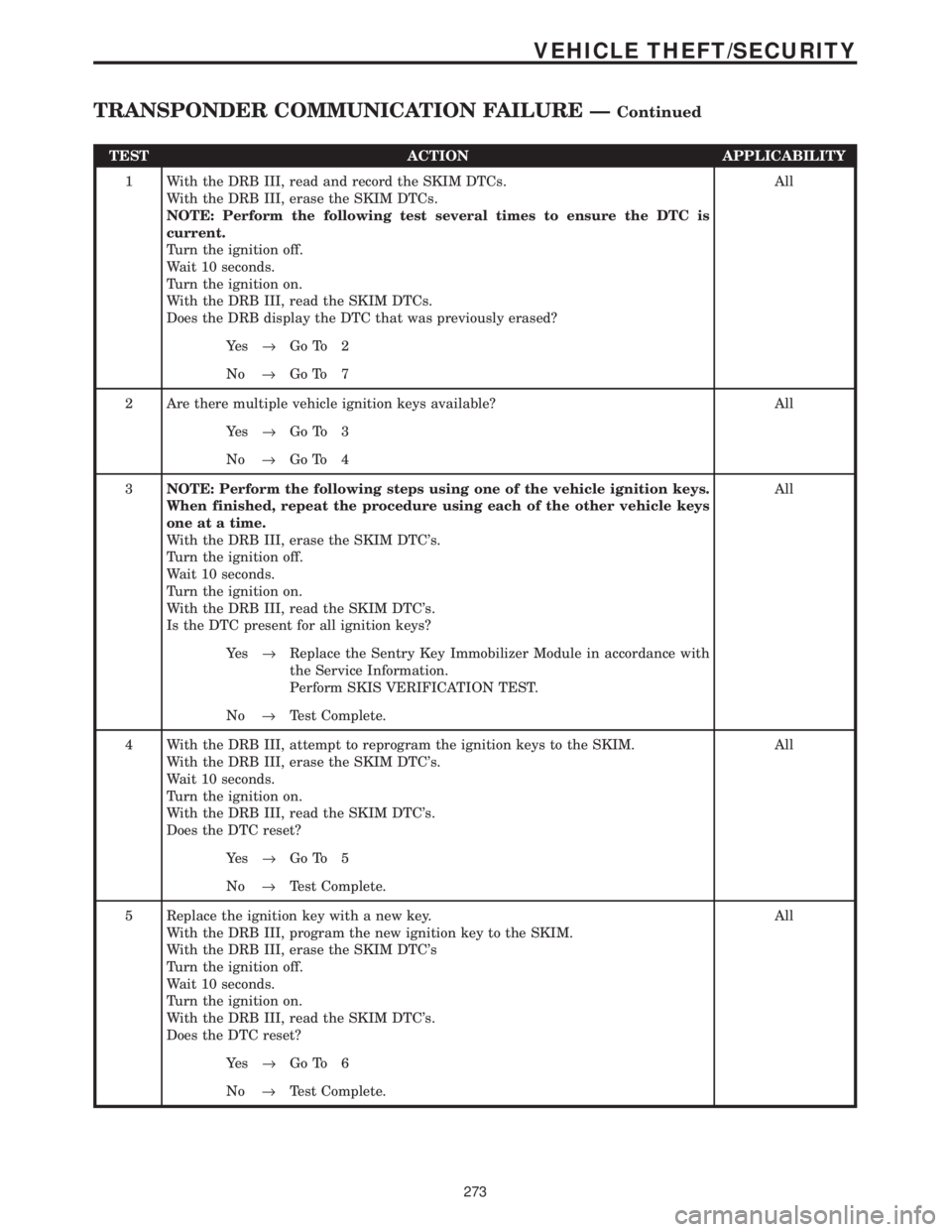
TEST ACTION APPLICABILITY
1 With the DRB III, read and record the SKIM DTCs.
With the DRB III, erase the SKIM DTCs.
NOTE: Perform the following test several times to ensure the DTC is
current.
Turn the ignition off.
Wait 10 seconds.
Turn the ignition on.
With the DRB III, read the SKIM DTCs.
Does the DRB display the DTC that was previously erased?All
Ye s®Go To 2
No®Go To 7
2 Are there multiple vehicle ignition keys available? All
Ye s®Go To 3
No®Go To 4
3NOTE: Perform the following steps using one of the vehicle ignition keys.
When finished, repeat the procedure using each of the other vehicle keys
one at a time.
With the DRB III, erase the SKIM DTC's.
Turn the ignition off.
Wait 10 seconds.
Turn the ignition on.
With the DRB III, read the SKIM DTC's.
Is the DTC present for all ignition keys?All
Ye s®Replace the Sentry Key Immobilizer Module in accordance with
the Service Information.
Perform SKIS VERIFICATION TEST.
No®Test Complete.
4 With the DRB III, attempt to reprogram the ignition keys to the SKIM.
With the DRB III, erase the SKIM DTC's.
Wait 10 seconds.
Turn the ignition on.
With the DRB III, read the SKIM DTC's.
Does the DTC reset?All
Ye s®Go To 5
No®Test Complete.
5 Replace the ignition key with a new key.
With the DRB III, program the new ignition key to the SKIM.
With the DRB III, erase the SKIM DTC's
Turn the ignition off.
Wait 10 seconds.
Turn the ignition on.
With the DRB III, read the SKIM DTC's.
Does the DTC reset?All
Ye s®Go To 6
No®Test Complete.
273
VEHICLE THEFT/SECURITY
TRANSPONDER COMMUNICATION FAILURE ÐContinued
Page 4069 of 4284
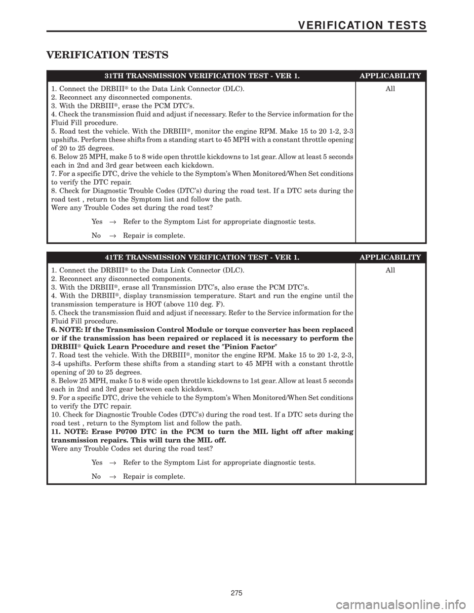
VERIFICATION TESTS
31TH TRANSMISSION VERIFICATION TEST - VER 1. APPLICABILITY
1. Connect the DRBIIItto the Data Link Connector (DLC).
2. Reconnect any disconnected components.
3. With the DRBIIIt, erase the PCM DTC's.
4. Check the transmission fluid and adjust if necessary. Refer to the Service information for the
Fluid Fill procedure.
5. Road test the vehicle. With the DRBIIIt, monitor the engine RPM. Make 15 to 20 1-2, 2-3
upshifts. Perform these shifts from a standing start to 45 MPH with a constant throttle opening
of 20 to 25 degrees.
6. Below 25 MPH, make 5 to 8 wide open throttle kickdowns to 1st gear. Allow at least 5 seconds
each in 2nd and 3rd gear between each kickdown.
7. For a specific DTC, drive the vehicle to the Symptom's When Monitored/When Set conditions
to verify the DTC repair.
8. Check for Diagnostic Trouble Codes (DTC's) during the road test. If a DTC sets during the
road test , return to the Symptom list and follow the path.
Were any Trouble Codes set during the road test?All
Ye s®Refer to the Symptom List for appropriate diagnostic tests.
No®Repair is complete.
41TE TRANSMISSION VERIFICATION TEST - VER 1. APPLICABILITY
1. Connect the DRBIIItto the Data Link Connector (DLC).
2. Reconnect any disconnected components.
3. With the DRBIIIt, erase all Transmission DTC's, also erase the PCM DTC's.
4. With the DRBIIIt, display transmission temperature. Start and run the engine until the
transmission temperature is HOT (above 110 deg. F).
5. Check the transmission fluid and adjust if necessary. Refer to the Service information for the
Fluid Fill procedure.
6. NOTE: If the Transmission Control Module or torque converter has been replaced
or if the transmission has been repaired or replaced it is necessary to perform the
DRBIIItQuick Learn Procedure and reset the(Pinion Factor(
7. Road test the vehicle. With the DRBIIIt, monitor the engine RPM. Make 15 to 20 1-2, 2-3,
3-4 upshifts. Perform these shifts from a standing start to 45 MPH with a constant throttle
opening of 20 to 25 degrees.
8. Below 25 MPH, make 5 to 8 wide open throttle kickdowns to 1st gear. Allow at least 5 seconds
each in 2nd and 3rd gear between each kickdown.
9. For a specific DTC, drive the vehicle to the Symptom's When Monitored/When Set conditions
to verify the DTC repair.
10. Check for Diagnostic Trouble Codes (DTC's) during the road test. If a DTC sets during the
road test , return to the Symptom list and follow the path.
11. NOTE: Erase P0700 DTC in the PCM to turn the MIL light off after making
transmission repairs. This will turn the MIL off.
Were any Trouble Codes set during the road test?All
Ye s®Refer to the Symptom List for appropriate diagnostic tests.
No®Repair is complete.
275
VERIFICATION TESTS
Page 4070 of 4284
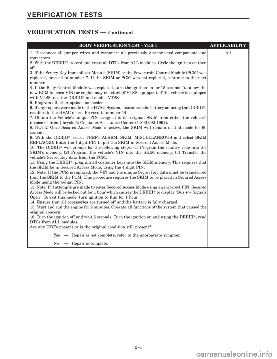
BODY VERIFICATION TEST - VER 1 APPLICABILITY
1. Disconnect all jumper wires and reconnect all previously disconnected components and
connectors.
2. With the DRBIIIt, record and erase all DTCs from ALL modules. Cycle the ignition on then
off
3. If the Sentry Key Immobilizer Module (SKIM) or the Powertrain Control Module (PCM) was
replaced, proceed to number 7. If the SKIM or PCM was not replaced, continue to the next
number.
4. If the Body Control Module was replaced, turn the ignition on for 15 seconds (to allow the
new BCM to learn VIN) or engine may not start (if VTSS equipped). If the vehicle is equipped
with VTSS, use the DRBIIItand enable VTSS.
5. Program all other options as needed.
6. If any repairs were made to the HVAC System, disconnect the battery or, using the DRBIIIt,
recalibrate the HVAC doors. Proceed to number 14.
7. Obtain the Vehicle's unique PIN assigned to it's original SKIM from either the vehicle's
invoice or from Chrysler's Customer Assistance Center (1-800-992-1997).
8. NOTE: Once Secured Access Mode is active, the SKIM will remain in that mode for 60
seconds.
9. With the DRBIIIt, select THEFT ALARM, SKIM, MISCELLANEOUS and select SKIM
REPLACED. Enter the 4 digit PIN to put the SKIM in Secured Access Mode.
10. The DRBIIItwill prompt for the following steps. (1) Program the country code into the
SKIM's memory. (2) Program the vehicle's VIN into the SKIM memory. (3) Transfer the
vehicle's Secret Key data from the PCM.
11. Using the DRBIIIt, program all customer keys into the SKIM memory. This requires that
the SKIM be in Secured Access Mode, using the 4 digit PIN.
12. Note: If the PCM is replaced, the VIN and the unique Secret Key data must be transferred
from the SKIM to the PCM. This procedure requires the SKIM to be placed in Secured Access
Mode using the 4-digit PIN.
13. Note: If 3 attempts are made to enter Secured Access Mode using an incorrect PIN, Secured
Access Mode will be locked out for 1 hour which causes the DRBIIItto display9Bus +\- Signals
Open9. To exit this mode, turn ignition to Run for 1 hour.
14. Ensure that all accessories are turned off and the battery is fully charged.
15. Start and run the engine for 2 minutes. Operate all functions of the system that caused the
original concern.
16. Turn the ignition off and wait 5 seconds. Turn the ignition on and using the DRBIIIt, read
DTCs from ALL modules.
Are any DTC's present or is the original condition still present?All
Ye s®Repair is not complete, refer to the appropriate symptom.
No®Repair is complete.
276
VERIFICATION TESTS
VERIFICATION TESTS ÐContinued