Page 3983 of 4284
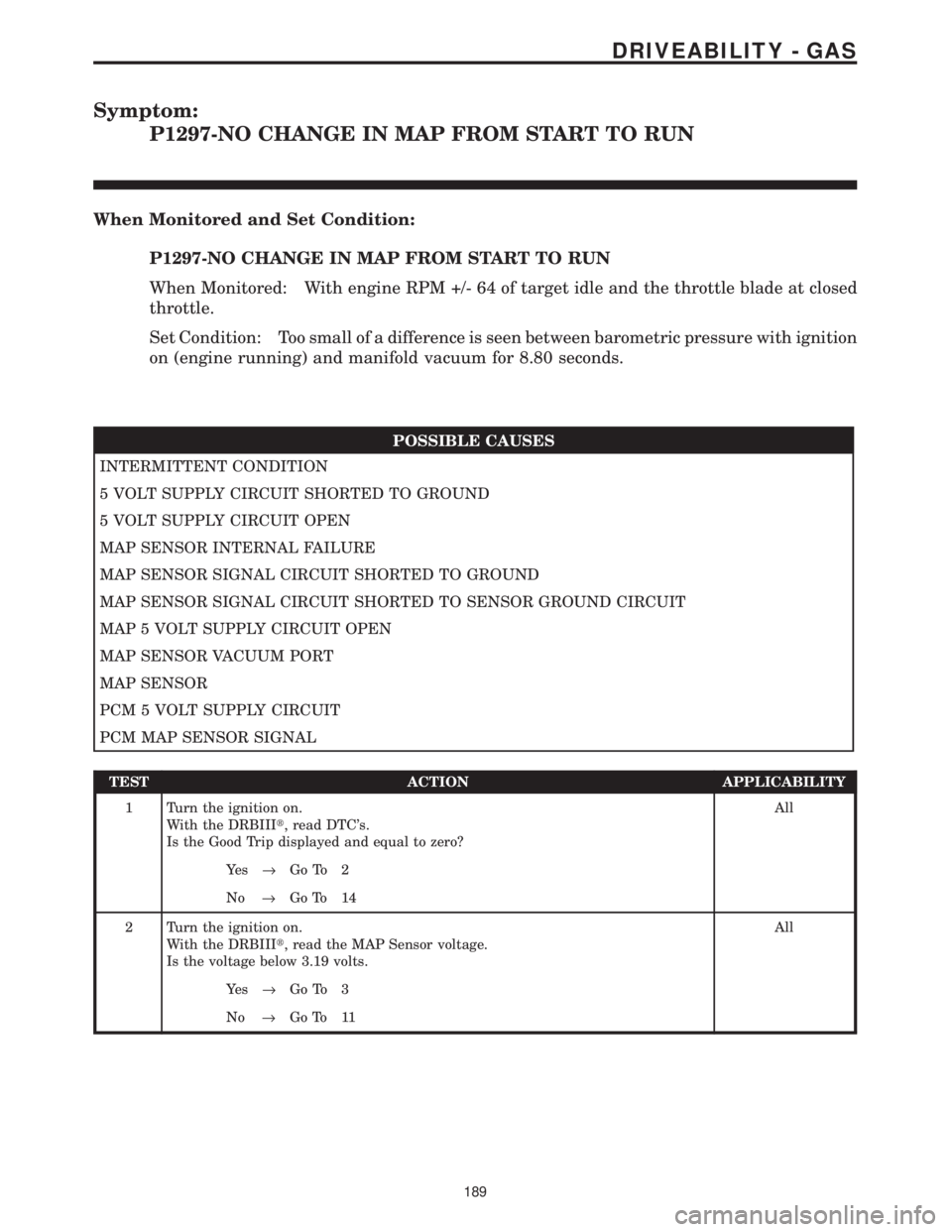
Symptom:
P1297-NO CHANGE IN MAP FROM START TO RUN
When Monitored and Set Condition:
P1297-NO CHANGE IN MAP FROM START TO RUN
When Monitored: With engine RPM +/- 64 of target idle and the throttle blade at closed
throttle.
Set Condition: Too small of a difference is seen between barometric pressure with ignition
on (engine running) and manifold vacuum for 8.80 seconds.
POSSIBLE CAUSES
INTERMITTENT CONDITION
5 VOLT SUPPLY CIRCUIT SHORTED TO GROUND
5 VOLT SUPPLY CIRCUIT OPEN
MAP SENSOR INTERNAL FAILURE
MAP SENSOR SIGNAL CIRCUIT SHORTED TO GROUND
MAP SENSOR SIGNAL CIRCUIT SHORTED TO SENSOR GROUND CIRCUIT
MAP 5 VOLT SUPPLY CIRCUIT OPEN
MAP SENSOR VACUUM PORT
MAP SENSOR
PCM 5 VOLT SUPPLY CIRCUIT
PCM MAP SENSOR SIGNAL
TEST ACTION APPLICABILITY
1 Turn the ignition on.
With the DRBIIIt, read DTC's.
Is the Good Trip displayed and equal to zero?All
Ye s®Go To 2
No®Go To 14
2 Turn the ignition on.
With the DRBIIIt, read the MAP Sensor voltage.
Is the voltage below 3.19 volts.All
Ye s®Go To 3
No®Go To 11
189
DRIVEABILITY - GAS
Page 3995 of 4284
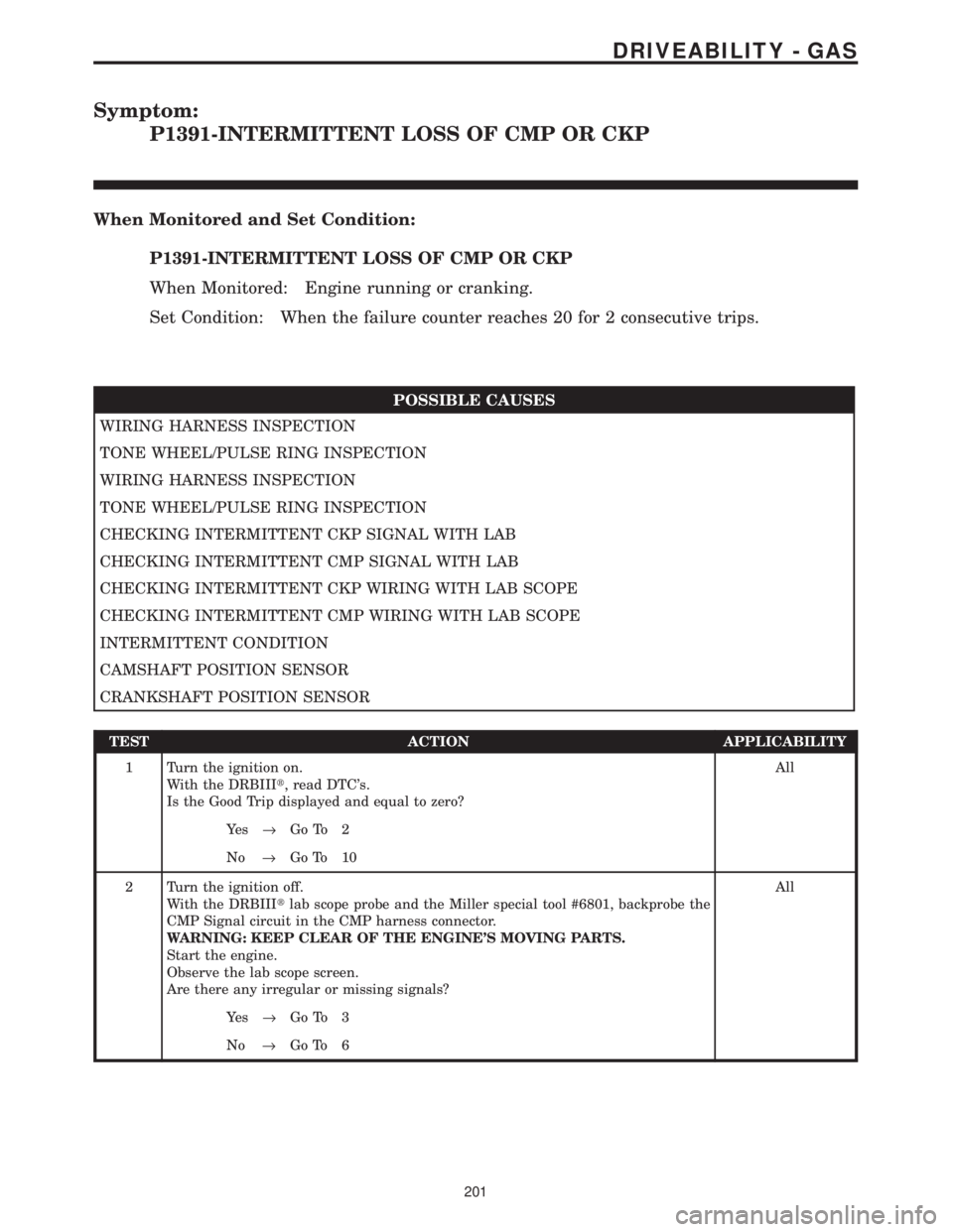
Symptom:
P1391-INTERMITTENT LOSS OF CMP OR CKP
When Monitored and Set Condition:
P1391-INTERMITTENT LOSS OF CMP OR CKP
When Monitored: Engine running or cranking.
Set Condition: When the failure counter reaches 20 for 2 consecutive trips.
POSSIBLE CAUSES
WIRING HARNESS INSPECTION
TONE WHEEL/PULSE RING INSPECTION
WIRING HARNESS INSPECTION
TONE WHEEL/PULSE RING INSPECTION
CHECKING INTERMITTENT CKP SIGNAL WITH LAB
CHECKING INTERMITTENT CMP SIGNAL WITH LAB
CHECKING INTERMITTENT CKP WIRING WITH LAB SCOPE
CHECKING INTERMITTENT CMP WIRING WITH LAB SCOPE
INTERMITTENT CONDITION
CAMSHAFT POSITION SENSOR
CRANKSHAFT POSITION SENSOR
TEST ACTION APPLICABILITY
1 Turn the ignition on.
With the DRBIIIt, read DTC's.
Is the Good Trip displayed and equal to zero?All
Ye s®Go To 2
No®Go To 10
2 Turn the ignition off.
With the DRBIIItlab scope probe and the Miller special tool #6801, backprobe the
CMP Signal circuit in the CMP harness connector.
WARNING: KEEP CLEAR OF THE ENGINE'S MOVING PARTS.
Start the engine.
Observe the lab scope screen.
Are there any irregular or missing signals?All
Ye s®Go To 3
No®Go To 6
201
DRIVEABILITY - GAS
Page 4001 of 4284
Symptom:
P1486-EVAP LEAK MONITOR PINCHED HOSE FOUND
When Monitored and Set Condition:
P1486-EVAP LEAK MONITOR PINCHED HOSE FOUND
When Monitored: Immediately after a cold start, with battery/ambient temperature
between 4ÉC (40ÉF) and 32ÉC (90ÉF) and coolant temperature within -12ÉC (10ÉF) of
battery/ambient.
Set Condition: LDP Switch does not reach at least 3 closures with 10 seconds. LDP must
initial in normal conditions to mature failure.
POSSIBLE CAUSES
INTERMITTENT LDP MONITOR FAILURE
OBSTRUCTION IN EVAP SYSTEM BETWEEN EVAP CANISTER AND FUEL TANK
EVAP CANISTER OBSTRUCTED
OBSTRUCTION IN HOSE/TUBE BETWEEN EVAP CANISTER AND PURGE SOLENOID
LDP PRESSURE HOSE OBSTRUCTED
LEAK DETECTION PUMP
TEST ACTION APPLICABILITY
1 Turn the ignition on.
With the DRBIIIt, read DTC's.
Is the Good Trip displayed and equal to zero?All
Ye s®Go To 2
No®Go To 6
207
DRIVEABILITY - GAS
Page 4008 of 4284
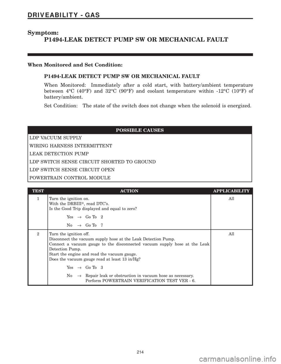
Symptom:
P1494-LEAK DETECT PUMP SW OR MECHANICAL FAULT
When Monitored and Set Condition:
P1494-LEAK DETECT PUMP SW OR MECHANICAL FAULT
When Monitored: Immediately after a cold start, with battery/ambient temperature
between 4ÉC (40ÉF) and 32ÉC (90ÉF) and coolant temperature within -12ÉC (10ÉF) of
battery/ambient.
Set Condition: The state of the switch does not change when the solenoid is energized.
POSSIBLE CAUSES
LDP VACUUM SUPPLY
WIRING HARNESS INTERMITTENT
LEAK DETECTION PUMP
LDP SWITCH SENSE CIRCUIT SHORTED TO GROUND
LDP SWITCH SENSE CIRCUIT OPEN
POWERTRAIN CONTROL MODULE
TEST ACTION APPLICABILITY
1 Turn the ignition on.
With the DRBIIIt, read DTC's.
Is the Good Trip displayed and equal to zero?All
Ye s®Go To 2
No®Go To 7
2 Turn the ignition off.
Disconnect the vacuum supply hose at the Leak Detection Pump.
Connect a vacuum gauge to the disconnected vacuum supply hose at the Leak
Detection Pump.
Start the engine and read the vacuum gauge.
Does the vacuum gauge read at least 13 in/Hg?All
Ye s®Go To 3
No®Repair leak or obstruction in vacuum hose as necessary.
Perform POWERTRAIN VERIFICATION TEST VER - 6.
214
DRIVEABILITY - GAS
Page 4010 of 4284
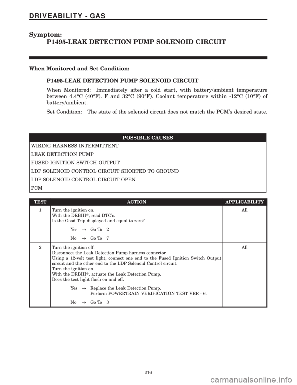
Symptom:
P1495-LEAK DETECTION PUMP SOLENOID CIRCUIT
When Monitored and Set Condition:
P1495-LEAK DETECTION PUMP SOLENOID CIRCUIT
When Monitored: Immediately after a cold start, with battery/ambient temperature
between 4.4ÉC (40ÉF). F and 32ÉC (90ÉF). Coolant temperature within -12ÉC (10ÉF) of
battery/ambient.
Set Condition: The state of the solenoid circuit does not match the PCM's desired state.
POSSIBLE CAUSES
WIRING HARNESS INTERMITTENT
LEAK DETECTION PUMP
FUSED IGNITION SWITCH OUTPUT
LDP SOLENOID CONTROL CIRCUIT SHORTED TO GROUND
LDP SOLENOID CONTROL CIRCUIT OPEN
PCM
TEST ACTION APPLICABILITY
1 Turn the ignition on.
With the DRBIIIt, read DTC's.
Is the Good Trip displayed and equal to zero?All
Ye s®Go To 2
No®Go To 7
2 Turn the ignition off.
Disconnect the Leak Detection Pump harness connector.
Using a 12-volt test light, connect one end to the Fused Ignition Switch Output
circuit and the other end to the LDP Solenoid Control circuit.
Turn the ignition on.
With the DRBIIIt, actuate the Leak Detection Pump.
Does the test light flash on and off.All
Ye s®Replace the Leak Detection Pump.
Perform POWERTRAIN VERIFICATION TEST VER - 6.
No®Go To 3
216
DRIVEABILITY - GAS
Page 4012 of 4284
Symptom:
P1496-5 VOLT SUPPLY, OUTPUT TOO LOW
When Monitored and Set Condition:
P1496-5 VOLT SUPPLY, OUTPUT TOO LOW
When Monitored: With the ignition on.
Set Condition: The 5-volt supply to the sensors is below 3.5 volts for 4 seconds.
POSSIBLE CAUSES
INTERMITTENT CONDITION
THROTTLE POSITION SENSOR
MAP SENSOR
A/C PRESSURE SENSOR
EGR SOLENOID
5 VOLT SUPPLY SHORTED TO GROUND
PCM
TEST ACTION APPLICABILITY
1 Turn the ignition on.
With the DRBIIIt, read the DTC's.
Is the Good Trip displayed and equal to zero?All
Ye s®Go To 2
No®Go To 9
2 Turn the ignition off.
Disconnect the Throttle Position Sensor harness connector.
Turn the ignition on.
Measure the 5 Volt Supply circuit at the Throttle Position Sensor harness connector.
Is the Voltage below 4.5 Volts?All
Ye s®Go To 3
No®Go To 8
218
DRIVEABILITY - GAS
Page 4013 of 4284
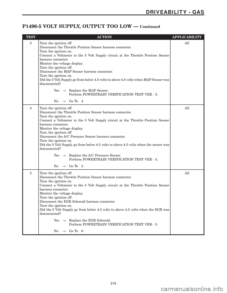
TEST ACTION APPLICABILITY
3 Turn the ignition off.
Disconnect the Throttle Position Sensor harness connector.
Turn the ignition on.
Connect a Voltmeter to the 5 Volt Supply circuit at the Throttle Position Sensor
harness connector.
Monitor the voltage display.
Turn the ignition off.
Disconnect the MAP Sensor harness connector.
Turn the ignition on.
Did the 5 Volt Supply go from below 4.5 volts to above 4.5 volts when MAP Sensor was
disconnected?All
Ye s®Replace the MAP Sensor.
Perform POWERTRAIN VERIFICATION TEST VER - 5.
No®Go To 4
4 Turn the ignition off.
Disconnect the Throttle Position Sensor harness connector.
Turn the ignition on.
Connect a Voltmeter to the 5 Volt Supply circuit at the Throttle Position Sensor
harness connector.
Monitor the voltage display.
Turn the ignition off.
Disconnect the A/C Pressure Sensor harness connector.
Turn the ignition on.
Did the 5 Volt Supply go from below 4.5 volts to above 4.5 volts when the sensor was
disconnected?All
Ye s®Replace the A/C Pressure Sensor.
Perform POWERTRAIN VERIFICATION TEST VER - 5.
No®Go To 5
5 Turn the ignition off.
Disconnect the Throttle Position Sensor harness connector.
Turn the ignition on.
Connect a Voltmeter to the 5 Volt Supply circuit at the Throttle Position Sensor
harness connector.
Monitor the voltage display.
Turn the ignition off.
Disconnect the EGR Solenoid harness connector.
Turn the ignition on.
Did the 5 Volt Supply go from below 4.5 volts to above 4.5 volts when the EGR was
disconnected?All
Ye s®Replace the EGR Solenoid.
Perform POWERTRAIN VERIFICATION TEST VER - 5.
No®Go To 6
219
DRIVEABILITY - GAS
P1496-5 VOLT SUPPLY, OUTPUT TOO LOW ÐContinued
Page 4016 of 4284
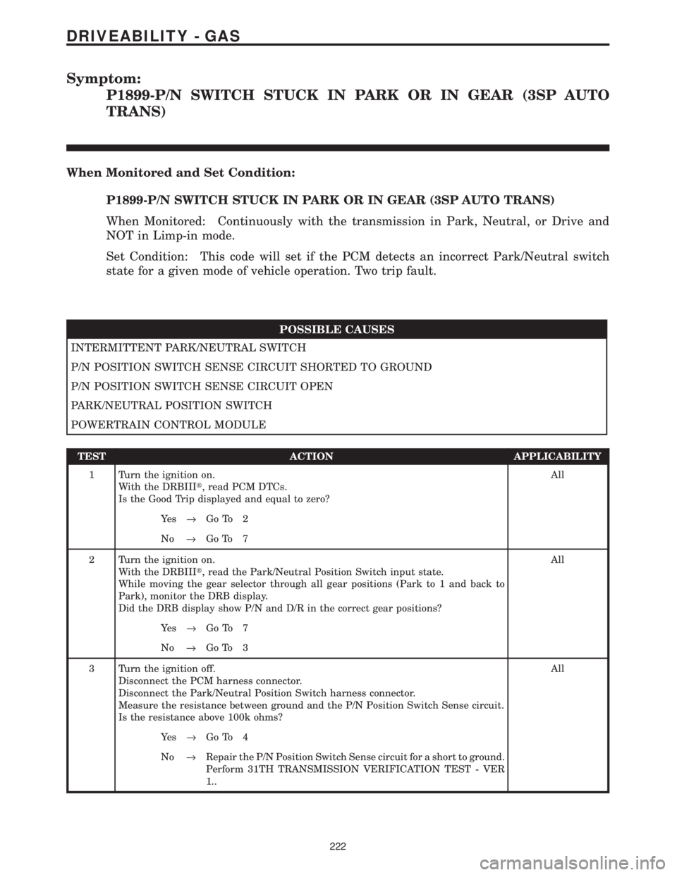
Symptom:
P1899-P/N SWITCH STUCK IN PARK OR IN GEAR (3SP AUTO
TRANS)
When Monitored and Set Condition:
P1899-P/N SWITCH STUCK IN PARK OR IN GEAR (3SP AUTO TRANS)
When Monitored: Continuously with the transmission in Park, Neutral, or Drive and
NOT in Limp-in mode.
Set Condition: This code will set if the PCM detects an incorrect Park/Neutral switch
state for a given mode of vehicle operation. Two trip fault.
POSSIBLE CAUSES
INTERMITTENT PARK/NEUTRAL SWITCH
P/N POSITION SWITCH SENSE CIRCUIT SHORTED TO GROUND
P/N POSITION SWITCH SENSE CIRCUIT OPEN
PARK/NEUTRAL POSITION SWITCH
POWERTRAIN CONTROL MODULE
TEST ACTION APPLICABILITY
1 Turn the ignition on.
With the DRBIIIt, read PCM DTCs.
Is the Good Trip displayed and equal to zero?All
Ye s®Go To 2
No®Go To 7
2 Turn the ignition on.
With the DRBIIIt, read the Park/Neutral Position Switch input state.
While moving the gear selector through all gear positions (Park to 1 and back to
Park), monitor the DRB display.
Did the DRB display show P/N and D/R in the correct gear positions?All
Ye s®Go To 7
No®Go To 3
3 Turn the ignition off.
Disconnect the PCM harness connector.
Disconnect the Park/Neutral Position Switch harness connector.
Measure the resistance between ground and the P/N Position Switch Sense circuit.
Is the resistance above 100k ohms?All
Ye s®Go To 4
No®Repair the P/N Position Switch Sense circuit for a short to ground.
Perform 31TH TRANSMISSION VERIFICATION TEST - VER
1..
222
DRIVEABILITY - GAS