2001 CHRYSLER VOYAGER display
[x] Cancel search: displayPage 4075 of 4284
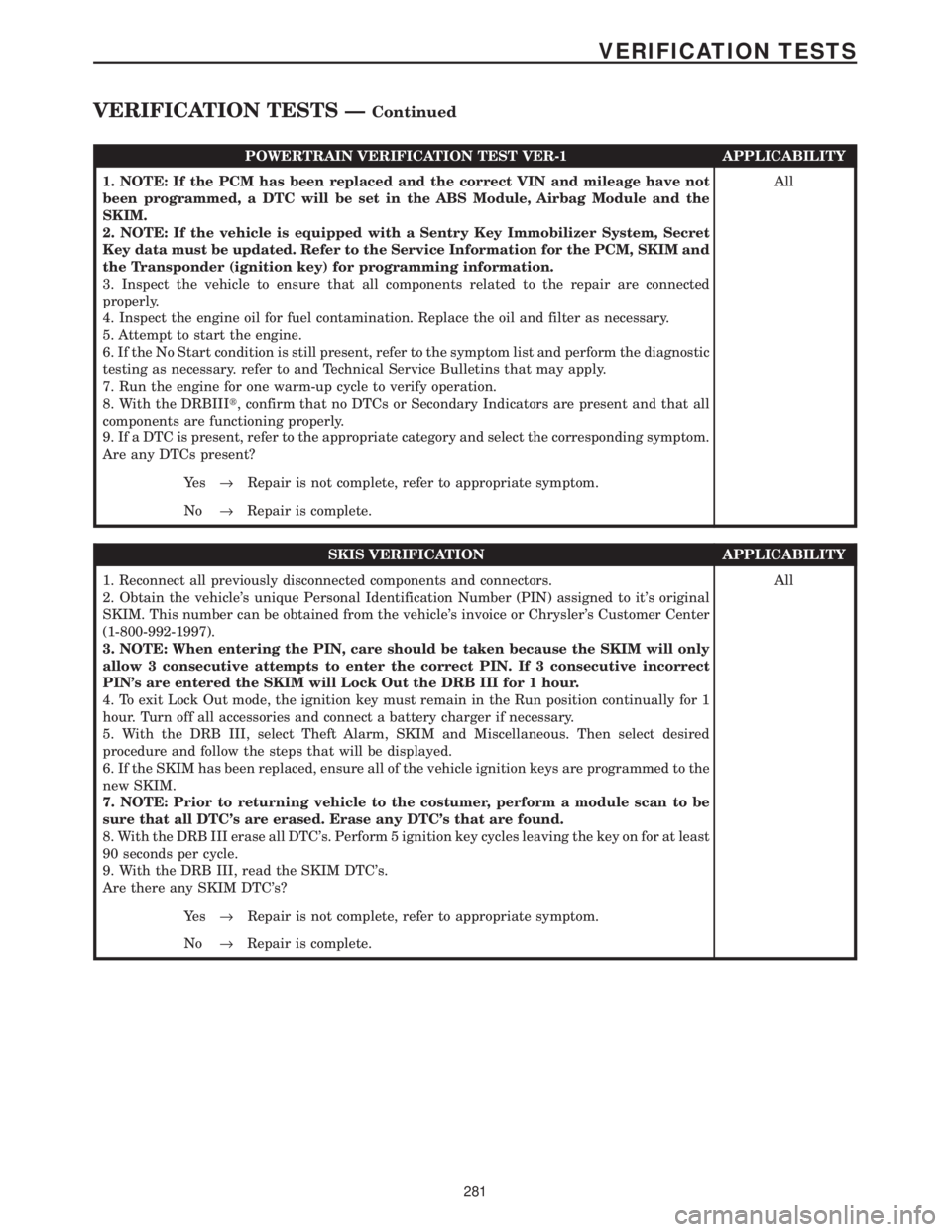
POWERTRAIN VERIFICATION TEST VER-1 APPLICABILITY
1. NOTE: If the PCM has been replaced and the correct VIN and mileage have not
been programmed, a DTC will be set in the ABS Module, Airbag Module and the
SKIM.
2. NOTE: If the vehicle is equipped with a Sentry Key Immobilizer System, Secret
Key data must be updated. Refer to the Service Information for the PCM, SKIM and
the Transponder (ignition key) for programming information.
3. Inspect the vehicle to ensure that all components related to the repair are connected
properly.
4. Inspect the engine oil for fuel contamination. Replace the oil and filter as necessary.
5. Attempt to start the engine.
6. If the No Start condition is still present, refer to the symptom list and perform the diagnostic
testing as necessary. refer to and Technical Service Bulletins that may apply.
7. Run the engine for one warm-up cycle to verify operation.
8. With the DRBIIIt, confirm that no DTCs or Secondary Indicators are present and that all
components are functioning properly.
9. If a DTC is present, refer to the appropriate category and select the corresponding symptom.
Are any DTCs present?All
Ye s®Repair is not complete, refer to appropriate symptom.
No®Repair is complete.
SKIS VERIFICATION APPLICABILITY
1. Reconnect all previously disconnected components and connectors.
2. Obtain the vehicle's unique Personal Identification Number (PIN) assigned to it's original
SKIM. This number can be obtained from the vehicle's invoice or Chrysler's Customer Center
(1-800-992-1997).
3. NOTE: When entering the PIN, care should be taken because the SKIM will only
allow 3 consecutive attempts to enter the correct PIN. If 3 consecutive incorrect
PIN's are entered the SKIM will Lock Out the DRB III for 1 hour.
4. To exit Lock Out mode, the ignition key must remain in the Run position continually for 1
hour. Turn off all accessories and connect a battery charger if necessary.
5. With the DRB III, select Theft Alarm, SKIM and Miscellaneous. Then select desired
procedure and follow the steps that will be displayed.
6. If the SKIM has been replaced, ensure all of the vehicle ignition keys are programmed to the
new SKIM.
7. NOTE: Prior to returning vehicle to the costumer, perform a module scan to be
sure that all DTC's are erased. Erase any DTC's that are found.
8. With the DRB III erase all DTC's. Perform 5 ignition key cycles leaving the key on for at least
90 seconds per cycle.
9. With the DRB III, read the SKIM DTC's.
Are there any SKIM DTC's?All
Ye s®Repair is not complete, refer to appropriate symptom.
No®Repair is complete.
281
VERIFICATION TESTS
VERIFICATION TESTS ÐContinued
Page 4101 of 4284
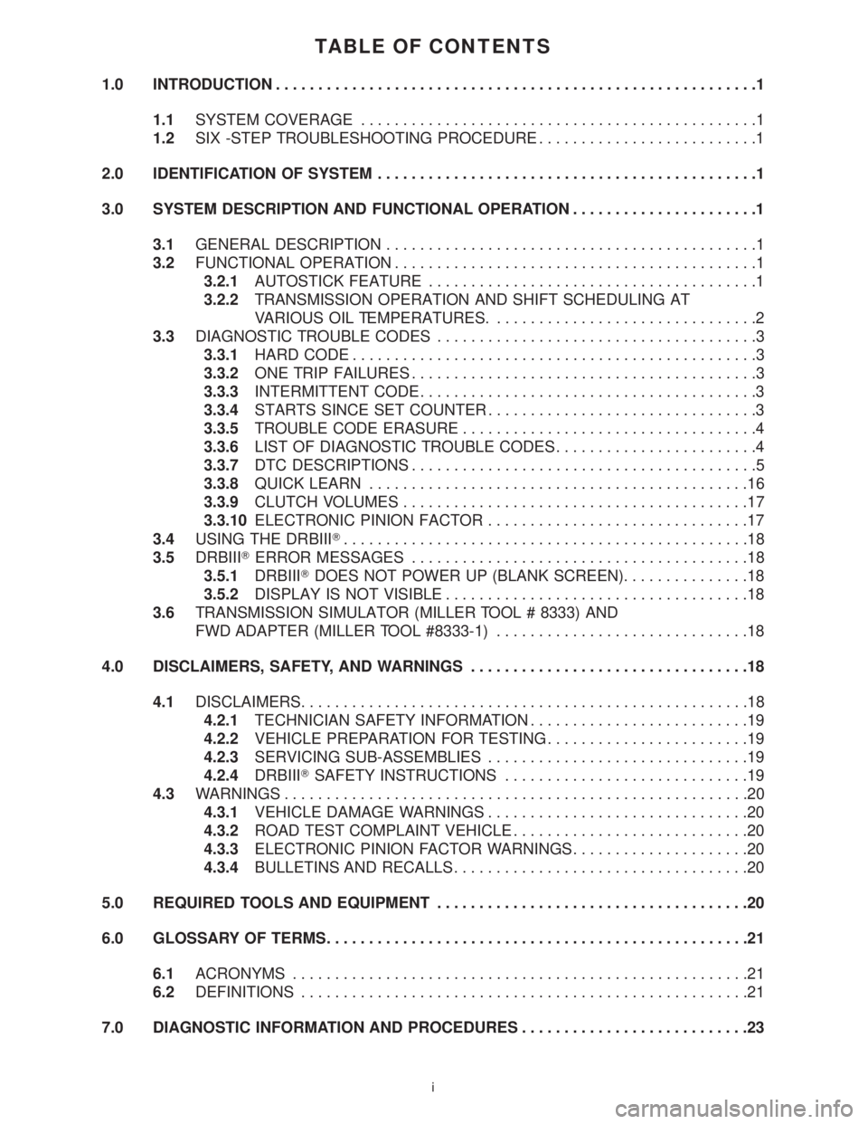
TABLE OF CONTENTS
1.0 INTRODUCTION.........................................................1
1.1SYSTEM COVERAGE...............................................1
1.2SIX -STEP TROUBLESHOOTING PROCEDURE..........................1
2.0 IDENTIFICATION OF SYSTEM.............................................1
3.0 SYSTEM DESCRIPTION AND FUNCTIONAL OPERATION......................1
3.1GENERAL DESCRIPTION............................................1
3.2FUNCTIONAL OPERATION...........................................1
3.2.1AUTOSTICK FEATURE.......................................1
3.2.2TRANSMISSION OPERATION AND SHIFT SCHEDULING AT
VARIOUS OIL TEMPERATURES................................2
3.3DIAGNOSTIC TROUBLE CODES......................................3
3.3.1HARD CODE................................................3
3.3.2ONE TRIP FAILURES.........................................3
3.3.3INTERMITTENT CODE........................................3
3.3.4STARTS SINCE SET COUNTER................................3
3.3.5TROUBLE CODE ERASURE...................................4
3.3.6LIST OF DIAGNOSTIC TROUBLE CODES........................4
3.3.7DTC DESCRIPTIONS.........................................5
3.3.8QUICK LEARN.............................................16
3.3.9CLUTCH VOLUMES.........................................17
3.3.10ELECTRONIC PINION FACTOR...............................17
3.4USING THE DRBIIIT................................................18
3.5DRBIIITERROR MESSAGES........................................18
3.5.1DRBIIITDOES NOT POWER UP (BLANK SCREEN)...............18
3.5.2DISPLAY IS NOT VISIBLE....................................18
3.6TRANSMISSION SIMULATOR (MILLER TOOL # 8333) AND
FWD ADAPTER (MILLER TOOL #8333-1)..............................18
4.0 DISCLAIMERS, SAFETY, AND WARNINGS.................................18
4.1DISCLAIMERS.....................................................18
4.2.1TECHNICIAN SAFETY INFORMATION..........................19
4.2.2VEHICLE PREPARATION FOR TESTING........................19
4.2.3SERVICING SUB-ASSEMBLIES...............................19
4.2.4DRBIIITSAFETY INSTRUCTIONS.............................19
4.3WARNINGS.......................................................20
4.3.1VEHICLE DAMAGE WARNINGS...............................20
4.3.2ROAD TEST COMPLAINT VEHICLE............................20
4.3.3ELECTRONIC PINION FACTOR WARNINGS.....................20
4.3.4BULLETINS AND RECALLS...................................20
5.0 REQUIRED TOOLS AND EQUIPMENT.....................................20
6.0 GLOSSARY OF TERMS..................................................21
6.1ACRONYMS......................................................21
6.2DEFINITIONS.....................................................21
7.0 DIAGNOSTIC INFORMATION AND PROCEDURES...........................23
i
Page 4105 of 4284

1.0 INTRODUCTION
The procedures contained in this manual include
all of the specifications, instructions, and graphics
needed to diagnose 41TE/AE Electronic Automatic
Transaxle (EATX) problems. The diagnostics in this
manual are based on the failure condition or symp-
tom being present at the time of diagnosis.
When repairs are required, refer to the appropri-
ate volume of the service manual for the proper
removal and repair procedure.
Diagnostic procedures change every year. New
diagnostic systems may be added and/or carryover
systems may be enhanced. READ THIS MANUAL
BEFORE TRYING TO DIAGNOSE A VEHICLE
TROUBLE CODE. It is recommended that you
review the entire manual to become familiar with
all new and changed diagnostic procedures.
This book reflects many suggested changes from
readers of past issues. After using this book, if you
have any comments or recommendations, please fill
out the form at the back of the book and mail it back
to us.
1.1 SYSTEM COVERAGE
This diagnostic procedures manual covers all
2001 RG equipped with a 41TE/AE transaxle.
1.2 SIX -STEP TROUBLESHOOTING
PROCEDURE
Diagnosis of the 41TE/AE electronic transaxle is
done in six basic steps:
verification of complaint
verification of any related symptoms
symptom analysis
problem isolation
repair of isolated problem
verification of proper operation
2.0 IDENTIFICATION OF
SYSTEM
RG series vehicles equipped with a 4 speed trans-
mission.
3.0 SYSTEM DESCRIPTION AND
FUNCTIONAL OPERATION
3.1 GENERAL DESCRIPTION
The 41TE/AE electronic transaxle is a conven-
tional transaxle in that it uses hydraulically ap-
plied clutches to shift a planetary gear train. How-
ever, the electronic control system replaces many of
the mechanical and hydraulic components used in
conventional transmission valve bodies.
3.2 FUNCTIONAL OPERATION
The 41TE/AE electronic transaxle has a fully
adaptive control system. The system performs it's
functions based on continuous real-time sensor
feedback information. The control system automat-
ically adapts to changes in engine performance and
friction element variations to provide consistent
shift quality. The control system ensures that clutch
operation during upshifting and downshifting is
more responsive without increased harshness.
The Transmission Control Module (TCM) contin-
uously checks for electrical problems, mechanical
problems, and some hydraulic problems. When a
problem is sensed, the TCM stores a diagnostic
trouble code. Some of these codes cause the tran-
saxle to go into limp-in or default mode.
While in this mode, electrical power is taken
away from the transaxle via the TCM, de-
energizing the transmission control relay, and tak-
ing power from the solenoid pack. When this hap-
pens, the only transaxle mechanical functions are:
Park and Neutral
Reverse
Second Gear
No upshifts or downshifts are possible. The posi-
tion of the manual valve alone allows the three
ranges that are available. Although vehicle perfor-
mance is seriously degraded while in this mode, it
allows the owner to drive the vehicle in for service.
Once the DRBIIItis in the EATX portion of the
diagnostic program, it constantly monitors the
TCM to see if the system is in limp-in mode. If the
transaxle is in limp-in mode, the DRBIIIž will flash
the red LED.
3.2.1 AUTOSTICK FEATURE
This feature allows the driver to manually shift
the transaxle when the shift lever is pulled back
into the AutoStick position. When in AutoStick
mode, the instrument cluster displays the current
gear.
1
GENERAL INFORMATION
Page 4107 of 4284
> Trailer towing in OD gear position (use 3 position
(or A/S 3rd) if frequent shifting occurs)
> Cooling system failure causing engine to operate
over 110C (230ÉF)
> Engine coolant temperature stays low too long -
If engine coolant temperature drops below 65C
(150ÉF), the transmission will disengage EMCC.
Extended operation with the EMCC disengaged
will cause the transmission to overheat.
> A brake switch issue will cause the EMCC to
disengage. Extended operation with the EMCC
disengaged will cause the transmission to over-
heat.
> Transmission fluid overfilled
> Transmission cooler or cooler lines restricted
> Transmission Temperature Sensor circuit
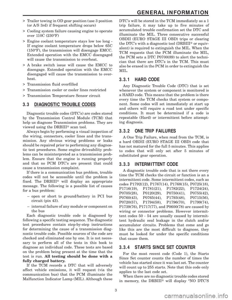
3.3 DIAGNOSTIC TROUBLE CODES
Diagnostic trouble codes (DTC's) are codes stored
by the Transmission Control Module (TCM) that
help us diagnose Transmission problems. They are
viewed using the DRBIIItscan tool.
Always begin by performing a visual inspection of
the wiring, connectors, cooler lines and the trans-
mission. Any obvious wiring problems or leaks
should be repaired prior to performing any diagnos-
tic test procedures. Some engine driveability prob-
lems can be misinterpreted as a transmission prob-
lem. Ensure that the engine is running properly
and that no PCM DTC's are present that could
cause a transmission complaint.
If there is a communication bus problem, trouble
codes will not be accessible until the problem is
fixed. The DRBIIItwill display an appropriate
message. The following is a possible list of causes
for a bus problem:
± open or short to ground/battery in PCI bus
circuit (pin 43).
± internal failure of any module or component on
the bus
Each diagnostic trouble code is diagnosed by
following a specific testing sequence. The diagnostic
test procedures contain step-by-step instructions
for determining the cause of a transmission diag-
nostic trouble code. Possible sources of the code are
checked and eliminated one by one. It is not neces-
sary to perform all of the tests in this book to
diagnose an individual code. These tests are based
on the problem being present at the time that the
test is run.All testing should be done with a
fully charged battery.
If the TCM records a DTC that will adversely
affect vehicle emissions, it will request (via the
communication bus) that the PCM illuminate the
Malfunction Indicator Lamp (MIL). Although theseDTC's will be stored in the TCM immediately as a 1
trip failure, it may take up to five minutes of
accumulated trouble confirmation set the DTC and
illuminate the MIL. Three consecutive successful
OBDII (EURO STAGE III OBD) trips or clearing
the DTC's with a diagnostic tool (DRBIIItor equiv-
alent) is required to extinguish the MIL. When the
TCM requests that the PCM illuminate the MIL,
the PCM sets a DTC P0700(89) to alert the techni-
cian that there are DTC's in the TCM. This must
also be erased in the PCM in order to extinguish the
MIL.
3.3.1 HARD CODE
Any Diagnostic Trouble Code (DTC) that is set
whenever the system or component is monitored is
a HARD code. This means that the problem is there
every time the TCM checks that system or compo-
nent. Some codes will set immediately at start up
and others will require a road test under specific
conditions. It must be determined if a code is
repeatable (Hard) or intermittent before attempt-
ing diagnosis.
3.3.2 ONE TRIP FAILURES
A One Trip Failure, when read from the TCM, is
a hard OBDII (EURO STAGE III OBD) code that
has not matured for the full 5 minutes. This applies
to codes that will only set after 5 minutes of
substituted gear operation.
3.3.3 INTERMITTENT CODE
A diagnostic trouble code that is not there every
time the TCM checks the circuit or function is an a
intermittent code. Some intermittent codes, such as
codes P1792(12), P1767(14), P1768(15), P0725(18),
P1716(19), P1781(21), P1782(22), P1724(24),
P0705(28), P0120(29), P0750(41), P0755(42),
P0760(43), P0765(44), P1793(48), P0715(56),
P0720(57), P1794(58), P1796(70), P1799(74),
P1739(76), P1717(77), and P0600(78) are caused by
wiring or connector problems. However intermit-
tent codes 50 - 54 are usually caused by intermit-
tent hydraulic seal leakage in the clutch and/or
accumulator circuits. Problems that come and go
like this are the most difficult to diagnose, they
must be looked for under the specific conditions
that cause them.
3.3.4 STARTS SINCE SET COUNTER
For the most recent code (Code 1), the Starts
Since Set counter counts the number of times the
vehicle has started since it was last set. The counter
will count up to 255 starts. Note that this code only
applies to the last code set.
When there are no diagnostic trouble codes stored
in memory, the DRBIIItwill display ``NO DTC'S
3
GENERAL INFORMATION
Page 4113 of 4284
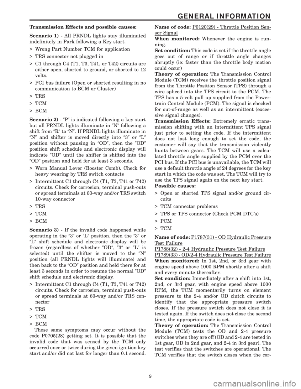
Transmission Effects and possible causes:
Scenario 1)- All PRNDL lights stay illuminated
indefinitely in Park following a Key start.
> Wrong Part Number TCM for application
> TRS connector not plugged in
> C1 through C4 (T1, T3, T41, or T42) circuits are
either open, shorted to ground, or shorted to 12
volts.
> PCI bus failure (Open or shorted resulting in no
communication to BCM or Cluster)
> TRS
> TCM
> BCM
Scenario 2)-9P9is indicated following a key start
but all PRNDL lights illuminate in9N9following a
shift from9R9to9N9. If PRNDL lights illuminate in
9N9and shifter is moved directly into939or9L9
position without pausing in9OD9, then the9OD9
position shift schedule and electronic display will
indicate9OD9until the shifter is shifted into the
9OD9position and held for at least 3 seconds.
> Worn Manual Lever (Rooster Comb). Check for
heavy wearing by TRS switch contacts
> Intermittent C1 through C4 (T1, T3, T41 or T42)
circuits. Check for corrosion, terminal push-outs
or spread terminals at 60-way and/or TRS switch
10-way connector
> TRS
> TCM
> BCM
Scenario 3)- If the invalid code happened while
operating in the939or9L9position, then the939or
9L9shift schedule and electronic display will be
frozen (regardless of whether9OD9,939or9L9is
selected) until the shifter is moved to the9N9
position (all PRNDL lights will illuminate) and
then back to the9OD9position and held there for at
least 3 seconds in order to resume the normal9OD9
shift schedule and electronic display.
> Intermittent C1 through C4 (T1, T3, T41 or T42)
circuits. Check for corrosion, terminal push-outs
or spread terminals at 60-way and/or TRS con-
nector
> TRS
> TCM
> BCM
These same symptoms may occur without the
code P0705(28) getting set. It is possible that the
invalid code that was sensed by the TCM only
occurred once or twice during the given ignition key
start and/or did not last for longer than 0.1 second.Name of code:P0120(29) - Throttle Position Sen-
sor Signal
When monitored:Whenever the engine is run-
ning.
Set condition:This code is set if the throttle angle
goes out of range or if throttle angle changes
abruptly (ie: faster than the throttle body motion
could occur)
Theory of operation:The Transmission Control
Module (TCM) receives the throttle position signal
from the Throttle Position Sensor (TPS) through a
wire spliced into the TPS circuit to the PCM. The
TPS has a 5-volt pull up supplied from the Power-
train Control Module (PCM). The signal is checked
for out-of-range as well as an intermittent (exces-
sive signal changes).
Transmission Effects:Extremely erratic trans-
mission shifting with an intermittent TPS signal
just prior to setting the code. If the intermittent
does not last long enough to set the code, the
customer will say that the transmission violently
hunts between gears. The TCM will use a calcu-
lated throttle angle supplied by the PCM over the
PCI bus. If the PCI bus is unavailable, the TCM will
use a default throttle angle of 24 degrees for the key
start in which the code was set. The TCM will try to
use the TPS signal again on the next key start.
Possible causes:
> Open or shorted TPS signal and/or ground cir-
cuits
> TCM connector problems
> TPS or TPS connector (Check PCM DTC's)
> PCM
> TCM
Name of code:P1787(31) - OD Hydraulic Pressure
Test Failure
P1788(32) - 2-4 Hydraulic Pressure Test Failure
P1789(33) - OD/2-4 Hydraulic Pressure Test Failure
When monitored:In 1st, 2nd, or 3rd gear with
engine speed above 1000 RPM shortly after a shift
and every minute thereafter.
Set condition:Immediately after a shift into 1st,
2nd, or 3rd gear, with engine speed above 1000
RPM, the TCM momentarily turns on element
pressure to the 2-4 and/or OD clutch circuits to
identify that the appropriate pressure switch
closes. If the pressure switch does not close it is
tested again. If the switch does not close the second
time, the appropriate code is set.
Theory of operation:The Transmission Control
Module (TCM) tests the OD and 2-4 pressure
switches when they are off (OD and 2-4 are tested in
1st gear, OD in 2nd gear, and 2-4 in 3rd gear). The
test verifies that the switches are operational. The
TCM verifies that the switch closes when the cor-
9
GENERAL INFORMATION
Page 4121 of 4284
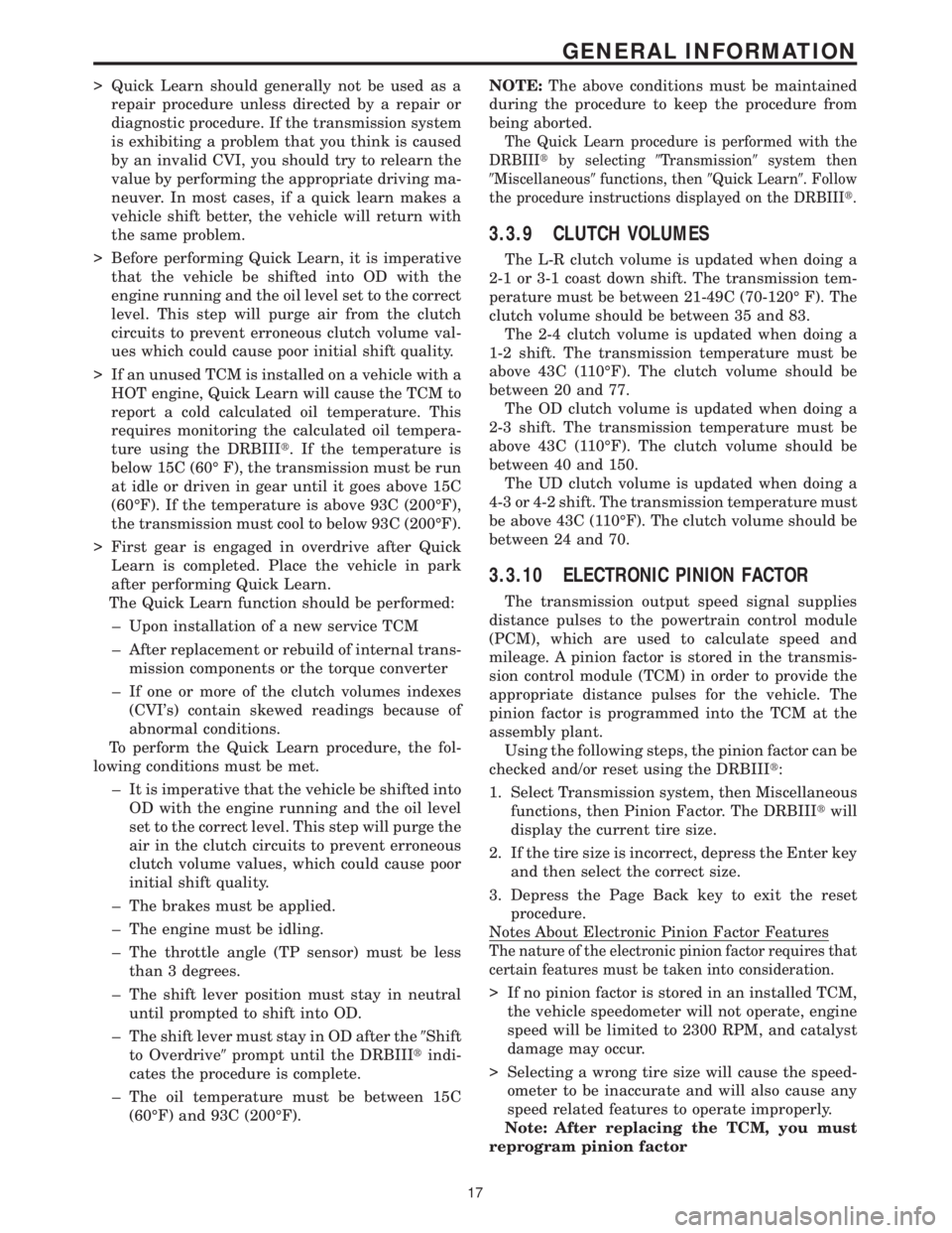
> Quick Learn should generally not be used as a
repair procedure unless directed by a repair or
diagnostic procedure. If the transmission system
is exhibiting a problem that you think is caused
by an invalid CVI, you should try to relearn the
value by performing the appropriate driving ma-
neuver. In most cases, if a quick learn makes a
vehicle shift better, the vehicle will return with
the same problem.
> Before performing Quick Learn, it is imperative
that the vehicle be shifted into OD with the
engine running and the oil level set to the correct
level. This step will purge air from the clutch
circuits to prevent erroneous clutch volume val-
ues which could cause poor initial shift quality.
> If an unused TCM is installed on a vehicle with a
HOT engine, Quick Learn will cause the TCM to
report a cold calculated oil temperature. This
requires monitoring the calculated oil tempera-
ture using the DRBIIIt. If the temperature is
below 15C (60É F), the transmission must be run
at idle or driven in gear until it goes above 15C
(60ÉF). If the temperature is above 93C (200ÉF),
the transmission must cool to below 93C (200ÉF).
> First gear is engaged in overdrive after Quick
Learn is completed. Place the vehicle in park
after performing Quick Learn.
The Quick Learn function should be performed:
± Upon installation of a new service TCM
± After replacement or rebuild of internal trans-
mission components or the torque converter
± If one or more of the clutch volumes indexes
(CVI's) contain skewed readings because of
abnormal conditions.
To perform the Quick Learn procedure, the fol-
lowing conditions must be met.
± It is imperative that the vehicle be shifted into
OD with the engine running and the oil level
set to the correct level. This step will purge the
air in the clutch circuits to prevent erroneous
clutch volume values, which could cause poor
initial shift quality.
± The brakes must be applied.
± The engine must be idling.
± The throttle angle (TP sensor) must be less
than 3 degrees.
± The shift lever position must stay in neutral
until prompted to shift into OD.
± The shift lever must stay in OD after the9Shift
to Overdrive9prompt until the DRBIIItindi-
cates the procedure is complete.
± The oil temperature must be between 15C
(60ÉF) and 93C (200ÉF).NOTE:The above conditions must be maintained
during the procedure to keep the procedure from
being aborted.
The Quick Learn procedure is performed with the
DRBIIItby selecting9Transmission9system then
9Miscellaneous9functions, then9Quick Learn9. Follow
the procedure instructions displayed on the DRBIIIt.
3.3.9 CLUTCH VOLUMES
The L-R clutch volume is updated when doing a
2-1 or 3-1 coast down shift. The transmission tem-
perature must be between 21-49C (70-120É F). The
clutch volume should be between 35 and 83.
The 2-4 clutch volume is updated when doing a
1-2 shift. The transmission temperature must be
above 43C (110ÉF). The clutch volume should be
between 20 and 77.
The OD clutch volume is updated when doing a
2-3 shift. The transmission temperature must be
above 43C (110ÉF). The clutch volume should be
between 40 and 150.
The UD clutch volume is updated when doing a
4-3 or 4-2 shift. The transmission temperature must
be above 43C (110ÉF). The clutch volume should be
between 24 and 70.
3.3.10 ELECTRONIC PINION FACTOR
The transmission output speed signal supplies
distance pulses to the powertrain control module
(PCM), which are used to calculate speed and
mileage. A pinion factor is stored in the transmis-
sion control module (TCM) in order to provide the
appropriate distance pulses for the vehicle. The
pinion factor is programmed into the TCM at the
assembly plant.
Using the following steps, the pinion factor can be
checked and/or reset using the DRBIIIt:
1. Select Transmission system, then Miscellaneous
functions, then Pinion Factor. The DRBIIItwill
display the current tire size.
2. If the tire size is incorrect, depress the Enter key
and then select the correct size.
3. Depress the Page Back key to exit the reset
procedure.
Notes About Electronic Pinion Factor Features
The nature of the electronic pinion factor requires that
certain features must be taken into consideration.
> If no pinion factor is stored in an installed TCM,
the vehicle speedometer will not operate, engine
speed will be limited to 2300 RPM, and catalyst
damage may occur.
> Selecting a wrong tire size will cause the speed-
ometer to be inaccurate and will also cause any
speed related features to operate improperly.
Note: After replacing the TCM, you must
reprogram pinion factor
17
GENERAL INFORMATION
Page 4122 of 4284
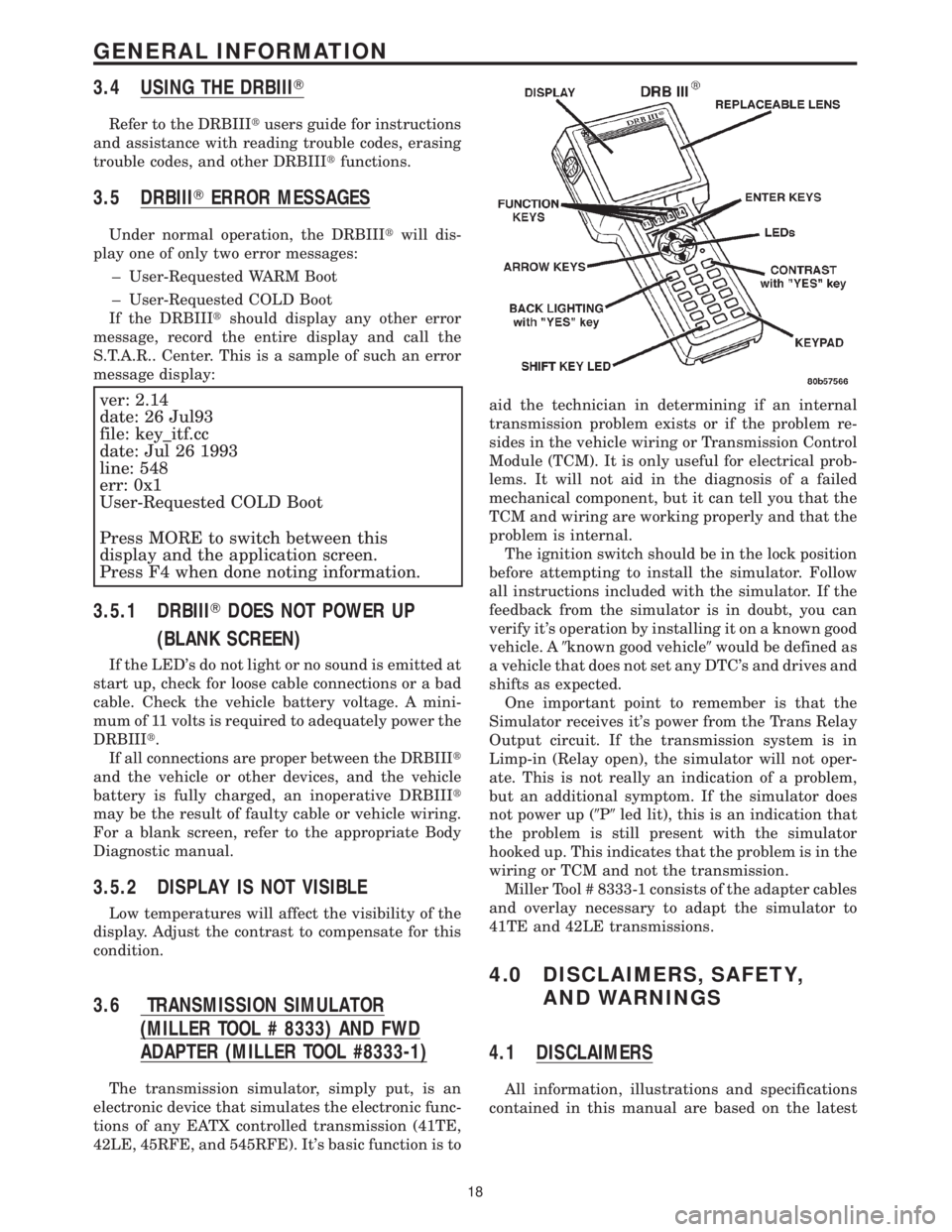
3.4 USING THE DRBIIIT
Refer to the DRBIIItusers guide for instructions
and assistance with reading trouble codes, erasing
trouble codes, and other DRBIIItfunctions.
3.5 DRBIIITERROR MESSAGES
Under normal operation, the DRBIIItwill dis-
play one of only two error messages:
± User-Requested WARM Boot
± User-Requested COLD Boot
If the DRBIIItshould display any other error
message, record the entire display and call the
S.T.A.R.. Center. This is a sample of such an error
message display:
ver: 2.14
date: 26 Jul93
file: key_itf.cc
date: Jul 26 1993
line: 548
err: 0x1
User-Requested COLD Boot
Press MORE to switch between this
display and the application screen.
Press F4 when done noting information.
3.5.1 DRBIIITDOES NOT POWER UP
(BLANK SCREEN)
If the LED's do not light or no sound is emitted at
start up, check for loose cable connections or a bad
cable. Check the vehicle battery voltage. A mini-
mum of 11 volts is required to adequately power the
DRBIIIt.
If all connections are proper between the DRBIIIt
and the vehicle or other devices, and the vehicle
battery is fully charged, an inoperative DRBIIIt
may be the result of faulty cable or vehicle wiring.
For a blank screen, refer to the appropriate Body
Diagnostic manual.
3.5.2 DISPLAY IS NOT VISIBLE
Low temperatures will affect the visibility of the
display. Adjust the contrast to compensate for this
condition.
3.6 TRANSMISSION SIMULATOR
(MILLER TOOL # 8333) AND FWD
ADAPTER (MILLER TOOL #8333-1)
The transmission simulator, simply put, is an
electronic device that simulates the electronic func-
tions of any EATX controlled transmission (41TE,
42LE, 45RFE, and 545RFE). It's basic function is toaid the technician in determining if an internal
transmission problem exists or if the problem re-
sides in the vehicle wiring or Transmission Control
Module (TCM). It is only useful for electrical prob-
lems. It will not aid in the diagnosis of a failed
mechanical component, but it can tell you that the
TCM and wiring are working properly and that the
problem is internal.
The ignition switch should be in the lock position
before attempting to install the simulator. Follow
all instructions included with the simulator. If the
feedback from the simulator is in doubt, you can
verify it's operation by installing it on a known good
vehicle. A9known good vehicle9would be defined as
a vehicle that does not set any DTC's and drives and
shifts as expected.
One important point to remember is that the
Simulator receives it's power from the Trans Relay
Output circuit. If the transmission system is in
Limp-in (Relay open), the simulator will not oper-
ate. This is not really an indication of a problem,
but an additional symptom. If the simulator does
not power up (9P9led lit), this is an indication that
the problem is still present with the simulator
hooked up. This indicates that the problem is in the
wiring or TCM and not the transmission.
Miller Tool # 8333-1 consists of the adapter cables
and overlay necessary to adapt the simulator to
41TE and 42LE transmissions.
4.0 DISCLAIMERS, SAFETY,
AND WARNINGS
4.1 DISCLAIMERS
All information, illustrations and specifications
contained in this manual are based on the latest
18
GENERAL INFORMATION
Page 4130 of 4284
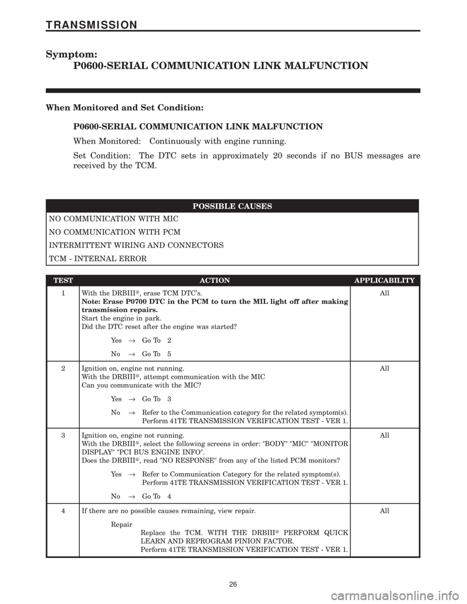
Symptom:
P0600-SERIAL COMMUNICATION LINK MALFUNCTION
When Monitored and Set Condition:
P0600-SERIAL COMMUNICATION LINK MALFUNCTION
When Monitored: Continuously with engine running.
Set Condition: The DTC sets in approximately 20 seconds if no BUS messages are
received by the TCM.
POSSIBLE CAUSES
NO COMMUNICATION WITH MIC
NO COMMUNICATION WITH PCM
INTERMITTENT WIRING AND CONNECTORS
TCM - INTERNAL ERROR
TEST ACTION APPLICABILITY
1 With the DRBIIIt, erase TCM DTC's.
Note: Erase P0700 DTC in the PCM to turn the MIL light off after making
transmission repairs.
Start the engine in park.
Did the DTC reset after the engine was started?All
Ye s®Go To 2
No®Go To 5
2 Ignition on, engine not running.
With the DRBIIIt, attempt communication with the MIC
Can you communicate with the MIC?All
Ye s®Go To 3
No®Refer to the Communication category for the related symptom(s).
Perform 41TE TRANSMISSION VERIFICATION TEST - VER 1.
3 Ignition on, engine not running.
With the DRBIIIt, select the following screens in order:9BODY99MIC99MONITOR
DISPLAY99PCI BUS ENGINE INFO9.
Does the DRBIIIt, read9NO RESPONSE9from any of the listed PCM monitors?All
Ye s®Refer to Communication Category for the related symptom(s).
Perform 41TE TRANSMISSION VERIFICATION TEST - VER 1.
No®Go To 4
4 If there are no possible causes remaining, view repair. All
Repair
Replace the TCM. WITH THE DRBIIItPERFORM QUICK
LEARN AND REPROGRAM PINION FACTOR.
Perform 41TE TRANSMISSION VERIFICATION TEST - VER 1.
26
TRANSMISSION