Page 4183 of 4284
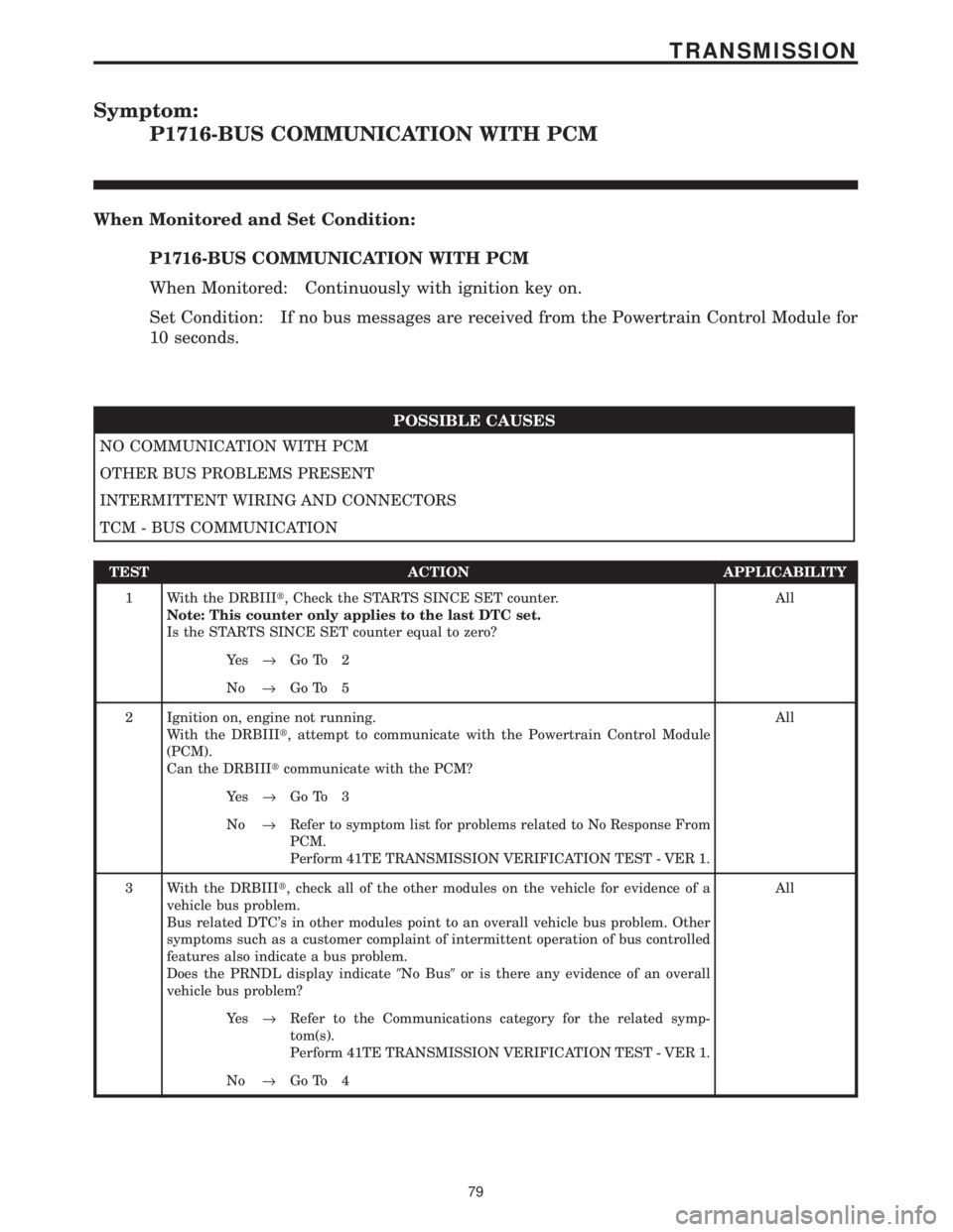
Symptom:
P1716-BUS COMMUNICATION WITH PCM
When Monitored and Set Condition:
P1716-BUS COMMUNICATION WITH PCM
When Monitored: Continuously with ignition key on.
Set Condition: If no bus messages are received from the Powertrain Control Module for
10 seconds.
POSSIBLE CAUSES
NO COMMUNICATION WITH PCM
OTHER BUS PROBLEMS PRESENT
INTERMITTENT WIRING AND CONNECTORS
TCM - BUS COMMUNICATION
TEST ACTION APPLICABILITY
1 With the DRBIIIt, Check the STARTS SINCE SET counter.
Note: This counter only applies to the last DTC set.
Is the STARTS SINCE SET counter equal to zero?All
Ye s®Go To 2
No®Go To 5
2 Ignition on, engine not running.
With the DRBIIIt, attempt to communicate with the Powertrain Control Module
(PCM).
Can the DRBIIItcommunicate with the PCM?All
Ye s®Go To 3
No®Refer to symptom list for problems related to No Response From
PCM.
Perform 41TE TRANSMISSION VERIFICATION TEST - VER 1.
3 With the DRBIIIt, check all of the other modules on the vehicle for evidence of a
vehicle bus problem.
Bus related DTC's in other modules point to an overall vehicle bus problem. Other
symptoms such as a customer complaint of intermittent operation of bus controlled
features also indicate a bus problem.
Does the PRNDL display indicate9No Bus9or is there any evidence of an overall
vehicle bus problem?All
Ye s®Refer to the Communications category for the related symp-
tom(s).
Perform 41TE TRANSMISSION VERIFICATION TEST - VER 1.
No®Go To 4
79
TRANSMISSION
Page 4185 of 4284
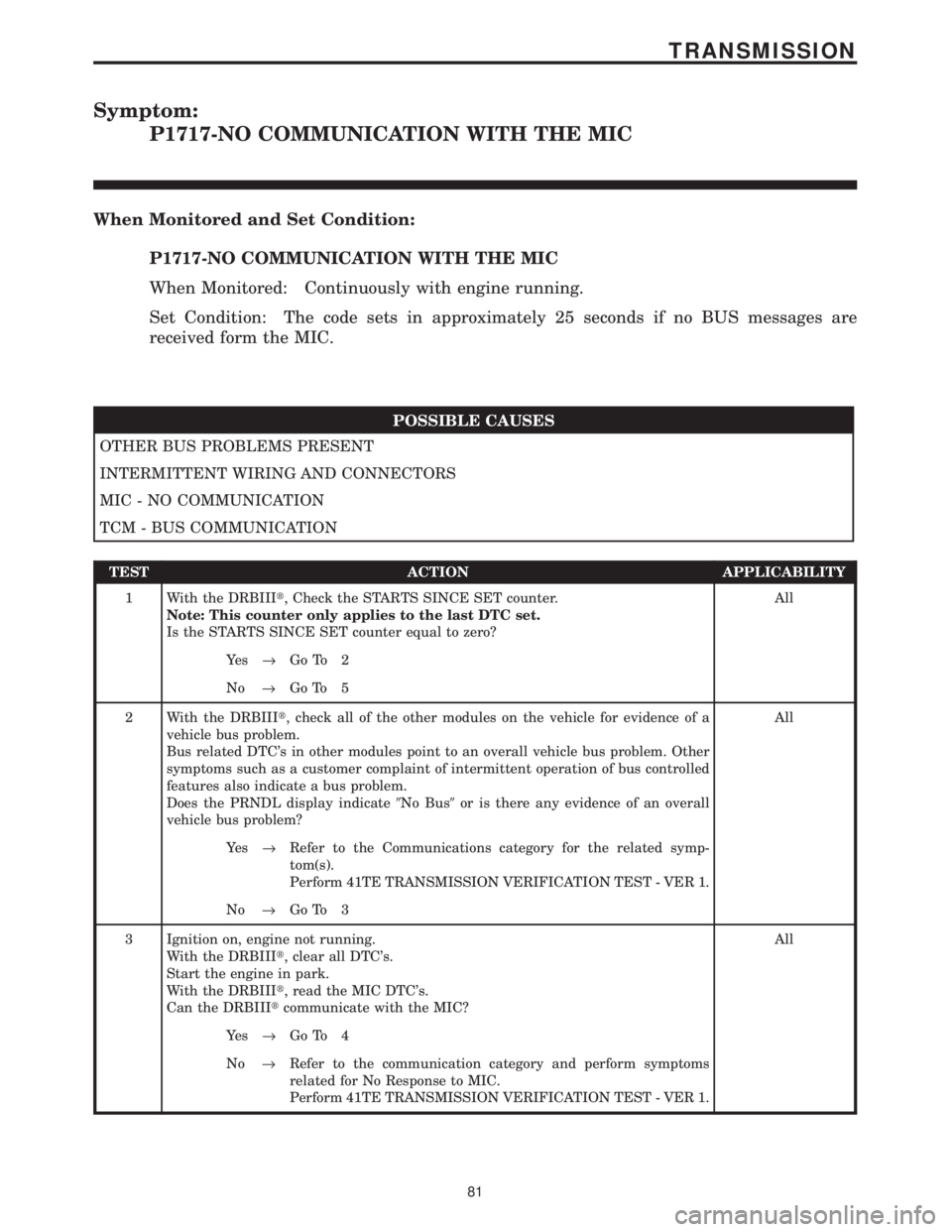
Symptom:
P1717-NO COMMUNICATION WITH THE MIC
When Monitored and Set Condition:
P1717-NO COMMUNICATION WITH THE MIC
When Monitored: Continuously with engine running.
Set Condition: The code sets in approximately 25 seconds if no BUS messages are
received form the MIC.
POSSIBLE CAUSES
OTHER BUS PROBLEMS PRESENT
INTERMITTENT WIRING AND CONNECTORS
MIC - NO COMMUNICATION
TCM - BUS COMMUNICATION
TEST ACTION APPLICABILITY
1 With the DRBIIIt, Check the STARTS SINCE SET counter.
Note: This counter only applies to the last DTC set.
Is the STARTS SINCE SET counter equal to zero?All
Ye s®Go To 2
No®Go To 5
2 With the DRBIIIt, check all of the other modules on the vehicle for evidence of a
vehicle bus problem.
Bus related DTC's in other modules point to an overall vehicle bus problem. Other
symptoms such as a customer complaint of intermittent operation of bus controlled
features also indicate a bus problem.
Does the PRNDL display indicate9No Bus9or is there any evidence of an overall
vehicle bus problem?All
Ye s®Refer to the Communications category for the related symp-
tom(s).
Perform 41TE TRANSMISSION VERIFICATION TEST - VER 1.
No®Go To 3
3 Ignition on, engine not running.
With the DRBIIIt, clear all DTC's.
Start the engine in park.
With the DRBIIIt, read the MIC DTC's.
Can the DRBIIItcommunicate with the MIC?All
Ye s®Go To 4
No®Refer to the communication category and perform symptoms
related for No Response to MIC.
Perform 41TE TRANSMISSION VERIFICATION TEST - VER 1.
81
TRANSMISSION
Page 4250 of 4284
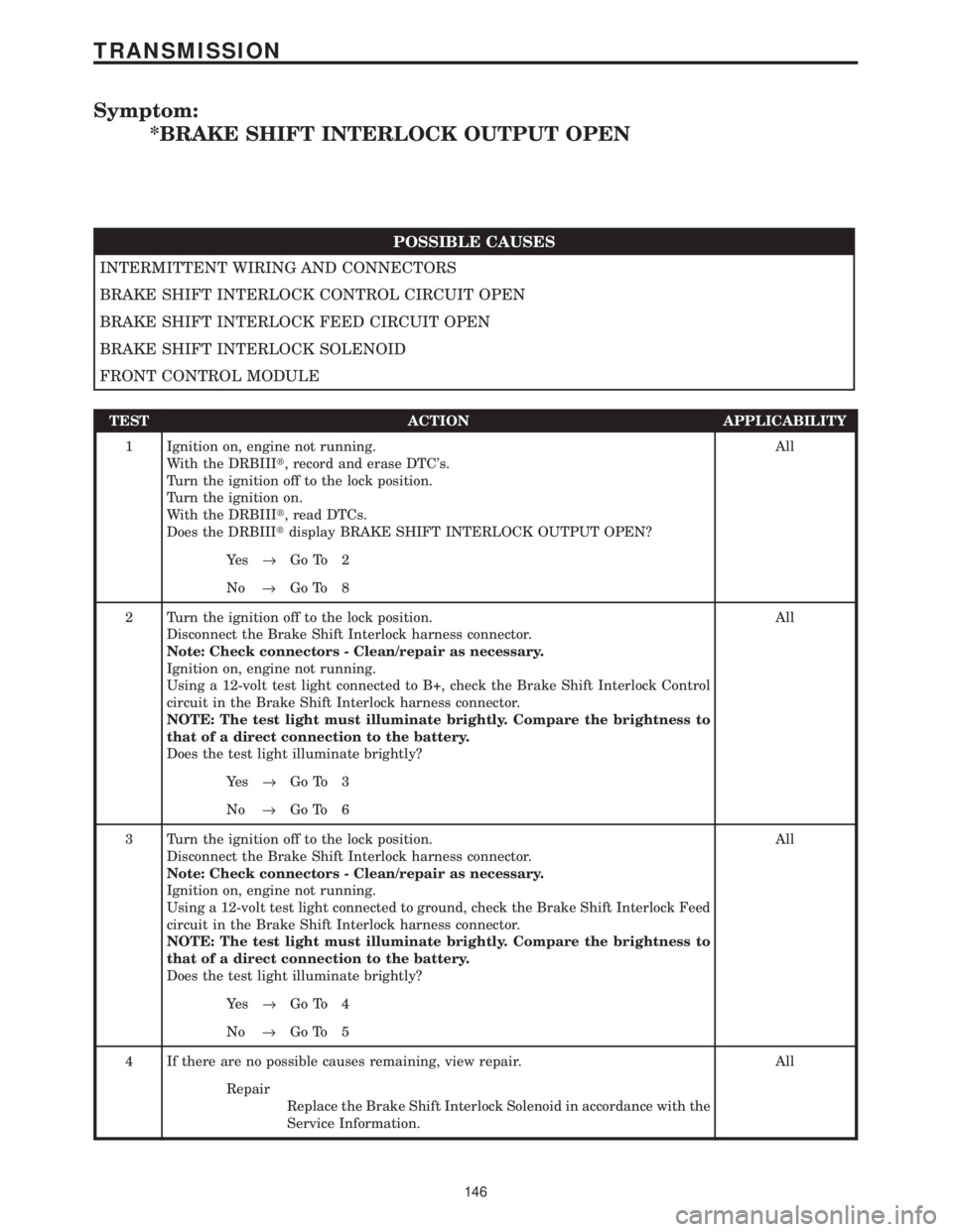
Symptom:
*BRAKE SHIFT INTERLOCK OUTPUT OPEN
POSSIBLE CAUSES
INTERMITTENT WIRING AND CONNECTORS
BRAKE SHIFT INTERLOCK CONTROL CIRCUIT OPEN
BRAKE SHIFT INTERLOCK FEED CIRCUIT OPEN
BRAKE SHIFT INTERLOCK SOLENOID
FRONT CONTROL MODULE
TEST ACTION APPLICABILITY
1 Ignition on, engine not running.
With the DRBIIIt, record and erase DTC's.
Turn the ignition off to the lock position.
Turn the ignition on.
With the DRBIIIt, read DTCs.
Does the DRBIIItdisplay BRAKE SHIFT INTERLOCK OUTPUT OPEN?All
Ye s®Go To 2
No®Go To 8
2 Turn the ignition off to the lock position.
Disconnect the Brake Shift Interlock harness connector.
Note: Check connectors - Clean/repair as necessary.
Ignition on, engine not running.
Using a 12-volt test light connected to B+, check the Brake Shift Interlock Control
circuit in the Brake Shift Interlock harness connector.
NOTE: The test light must illuminate brightly. Compare the brightness to
that of a direct connection to the battery.
Does the test light illuminate brightly?All
Ye s®Go To 3
No®Go To 6
3 Turn the ignition off to the lock position.
Disconnect the Brake Shift Interlock harness connector.
Note: Check connectors - Clean/repair as necessary.
Ignition on, engine not running.
Using a 12-volt test light connected to ground, check the Brake Shift Interlock Feed
circuit in the Brake Shift Interlock harness connector.
NOTE: The test light must illuminate brightly. Compare the brightness to
that of a direct connection to the battery.
Does the test light illuminate brightly?All
Ye s®Go To 4
No®Go To 5
4 If there are no possible causes remaining, view repair. All
Repair
Replace the Brake Shift Interlock Solenoid in accordance with the
Service Information.
146
TRANSMISSION
Page 4252 of 4284
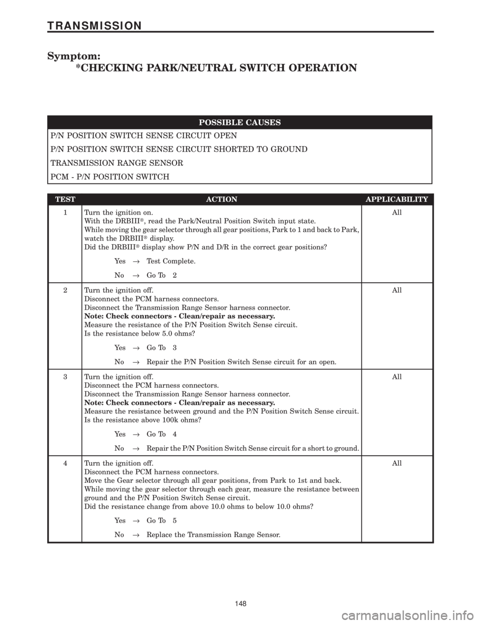
Symptom:
*CHECKING PARK/NEUTRAL SWITCH OPERATION
POSSIBLE CAUSES
P/N POSITION SWITCH SENSE CIRCUIT OPEN
P/N POSITION SWITCH SENSE CIRCUIT SHORTED TO GROUND
TRANSMISSION RANGE SENSOR
PCM - P/N POSITION SWITCH
TEST ACTION APPLICABILITY
1 Turn the ignition on.
With the DRBIIIt, read the Park/Neutral Position Switch input state.
While moving the gear selector through all gear positions, Park to 1 and back to Park,
watch the DRBIIItdisplay.
Did the DRBIIItdisplay show P/N and D/R in the correct gear positions?All
Ye s®Test Complete.
No®Go To 2
2 Turn the ignition off.
Disconnect the PCM harness connectors.
Disconnect the Transmission Range Sensor harness connector.
Note: Check connectors - Clean/repair as necessary.
Measure the resistance of the P/N Position Switch Sense circuit.
Is the resistance below 5.0 ohms?All
Ye s®Go To 3
No®Repair the P/N Position Switch Sense circuit for an open.
3 Turn the ignition off.
Disconnect the PCM harness connectors.
Disconnect the Transmission Range Sensor harness connector.
Note: Check connectors - Clean/repair as necessary.
Measure the resistance between ground and the P/N Position Switch Sense circuit.
Is the resistance above 100k ohms?All
Ye s®Go To 4
No®Repair the P/N Position Switch Sense circuit for a short to ground.
4 Turn the ignition off.
Disconnect the PCM harness connectors.
Move the Gear selector through all gear positions, from Park to 1st and back.
While moving the gear selector through each gear, measure the resistance between
ground and the P/N Position Switch Sense circuit.
Did the resistance change from above 10.0 ohms to below 10.0 ohms?All
Ye s®Go To 5
No®Replace the Transmission Range Sensor.
148
TRANSMISSION
Page 4261 of 4284
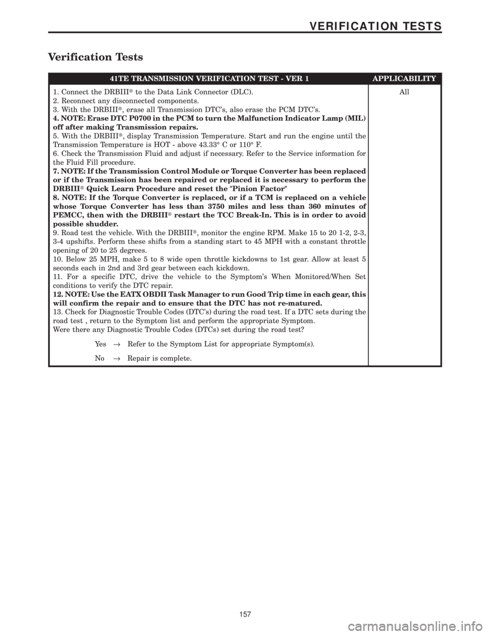
Verification Tests
41TE TRANSMISSION VERIFICATION TEST - VER 1 APPLICABILITY
1. Connect the DRBIIItto the Data Link Connector (DLC).
2. Reconnect any disconnected components.
3. With the DRBIIIt, erase all Transmission DTC's, also erase the PCM DTC's.
4. NOTE: Erase DTC P0700 in the PCM to turn the Malfunction Indicator Lamp (MIL)
off after making Transmission repairs.
5. With the DRBIIIt, display Transmission Temperature. Start and run the engine until the
Transmission Temperature is HOT - above 43.33É C or 110É F.
6. Check the Transmission Fluid and adjust if necessary. Refer to the Service information for
the Fluid Fill procedure.
7. NOTE: If the Transmission Control Module or Torque Converter has been replaced
or if the Transmission has been repaired or replaced it is necessary to perform the
DRBIIItQuick Learn Procedure and reset the(Pinion Factor(
8. NOTE: If the Torque Converter is replaced, or if a TCM is replaced on a vehicle
whose Torque Converter has less than 3750 miles and less than 360 minutes of
PEMCC, then with the DRBIIItrestart the TCC Break-In. This is in order to avoid
possible shudder.
9. Road test the vehicle. With the DRBIIIt, monitor the engine RPM. Make 15 to 20 1-2, 2-3,
3-4 upshifts. Perform these shifts from a standing start to 45 MPH with a constant throttle
opening of 20 to 25 degrees.
10. Below 25 MPH, make 5 to 8 wide open throttle kickdowns to 1st gear. Allow at least 5
seconds each in 2nd and 3rd gear between each kickdown.
11. For a specific DTC, drive the vehicle to the Symptom's When Monitored/When Set
conditions to verify the DTC repair.
12. NOTE: Use the EATX OBDII Task Manager to run Good Trip time in each gear, this
will confirm the repair and to ensure that the DTC has not re-matured.
13. Check for Diagnostic Trouble Codes (DTC's) during the road test. If a DTC sets during the
road test , return to the Symptom list and perform the appropriate Symptom.
Were there any Diagnostic Trouble Codes (DTCs) set during the road test?All
Ye s®Refer to the Symptom List for appropriate Symptom(s).
No®Repair is complete.
157
VERIFICATION TESTS