2001 CHRYSLER VOYAGER display
[x] Cancel search: displayPage 3907 of 4284
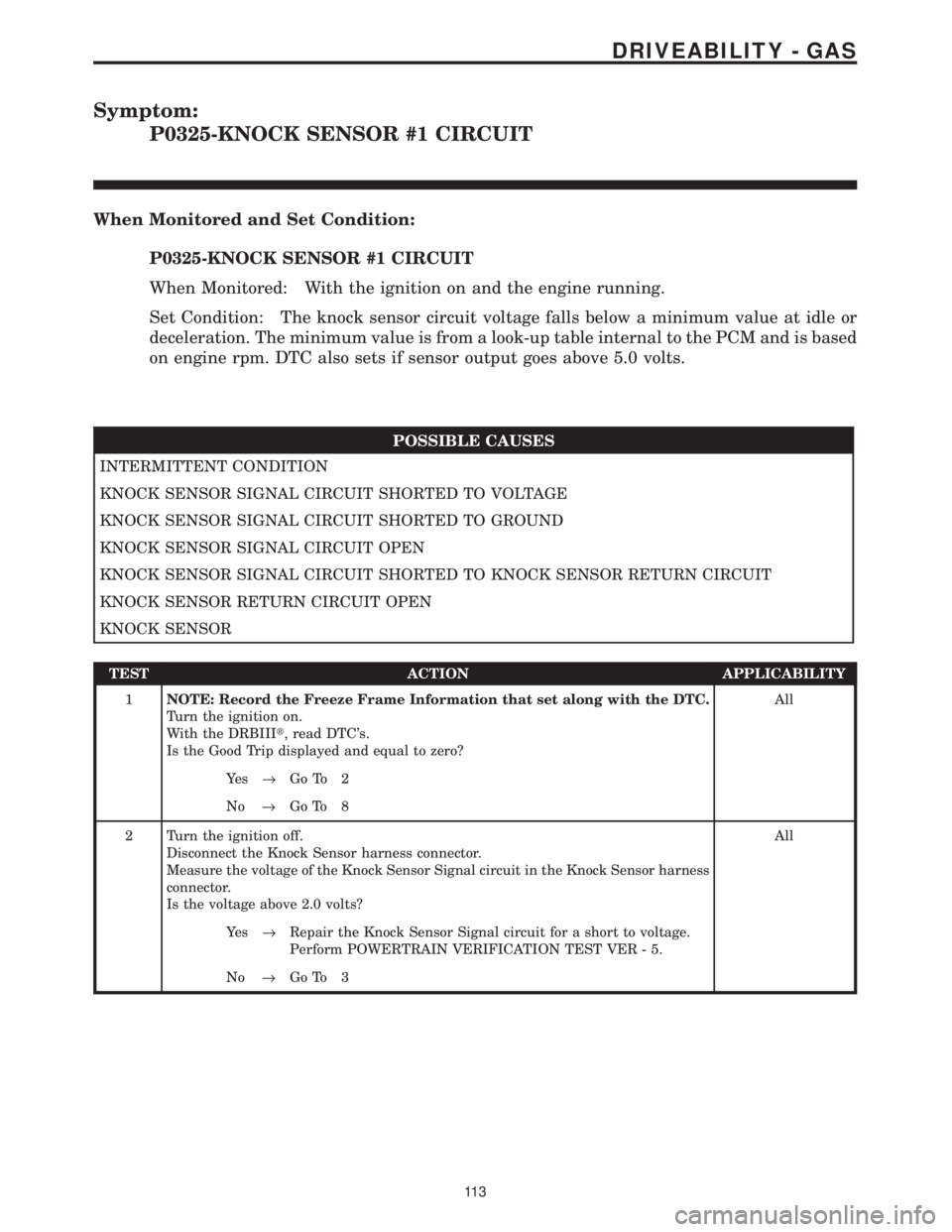
Symptom:
P0325-KNOCK SENSOR #1 CIRCUIT
When Monitored and Set Condition:
P0325-KNOCK SENSOR #1 CIRCUIT
When Monitored: With the ignition on and the engine running.
Set Condition: The knock sensor circuit voltage falls below a minimum value at idle or
deceleration. The minimum value is from a look-up table internal to the PCM and is based
on engine rpm. DTC also sets if sensor output goes above 5.0 volts.
POSSIBLE CAUSES
INTERMITTENT CONDITION
KNOCK SENSOR SIGNAL CIRCUIT SHORTED TO VOLTAGE
KNOCK SENSOR SIGNAL CIRCUIT SHORTED TO GROUND
KNOCK SENSOR SIGNAL CIRCUIT OPEN
KNOCK SENSOR SIGNAL CIRCUIT SHORTED TO KNOCK SENSOR RETURN CIRCUIT
KNOCK SENSOR RETURN CIRCUIT OPEN
KNOCK SENSOR
TEST ACTION APPLICABILITY
1NOTE: Record the Freeze Frame Information that set along with the DTC.
Turn the ignition on.
With the DRBIIIt, read DTC's.
Is the Good Trip displayed and equal to zero?All
Ye s®Go To 2
No®Go To 8
2 Turn the ignition off.
Disconnect the Knock Sensor harness connector.
Measure the voltage of the Knock Sensor Signal circuit in the Knock Sensor harness
connector.
Is the voltage above 2.0 volts?All
Ye s®Repair the Knock Sensor Signal circuit for a short to voltage.
Perform POWERTRAIN VERIFICATION TEST VER - 5.
No®Go To 3
11 3
DRIVEABILITY - GAS
Page 3908 of 4284
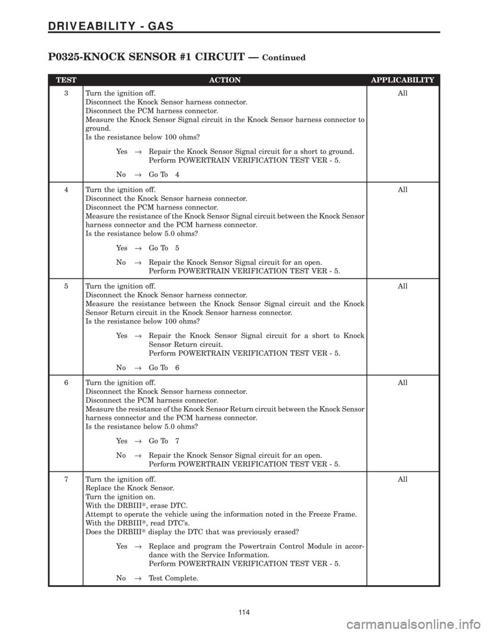
TEST ACTION APPLICABILITY
3 Turn the ignition off.
Disconnect the Knock Sensor harness connector.
Disconnect the PCM harness connector.
Measure the Knock Sensor Signal circuit in the Knock Sensor harness connector to
ground.
Is the resistance below 100 ohms?All
Ye s®Repair the Knock Sensor Signal circuit for a short to ground.
Perform POWERTRAIN VERIFICATION TEST VER - 5.
No®Go To 4
4 Turn the ignition off.
Disconnect the Knock Sensor harness connector.
Disconnect the PCM harness connector.
Measure the resistance of the Knock Sensor Signal circuit between the Knock Sensor
harness connector and the PCM harness connector.
Is the resistance below 5.0 ohms?All
Ye s®Go To 5
No®Repair the Knock Sensor Signal circuit for an open.
Perform POWERTRAIN VERIFICATION TEST VER - 5.
5 Turn the ignition off.
Disconnect the Knock Sensor harness connector.
Measure the resistance between the Knock Sensor Signal circuit and the Knock
Sensor Return circuit in the Knock Sensor harness connector.
Is the resistance below 100 ohms?All
Ye s®Repair the Knock Sensor Signal circuit for a short to Knock
Sensor Return circuit.
Perform POWERTRAIN VERIFICATION TEST VER - 5.
No®Go To 6
6 Turn the ignition off.
Disconnect the Knock Sensor harness connector.
Disconnect the PCM harness connector.
Measure the resistance of the Knock Sensor Return circuit between the Knock Sensor
harness connector and the PCM harness connector.
Is the resistance below 5.0 ohms?All
Ye s®Go To 7
No®Repair the Knock Sensor Signal circuit for an open.
Perform POWERTRAIN VERIFICATION TEST VER - 5.
7 Turn the ignition off.
Replace the Knock Sensor.
Turn the ignition on.
With the DRBIIIt, erase DTC.
Attempt to operate the vehicle using the information noted in the Freeze Frame.
With the DRBIIIt, read DTC's.
Does the DRBIIItdisplay the DTC that was previously erased?All
Ye s®Replace and program the Powertrain Control Module in accor-
dance with the Service Information.
Perform POWERTRAIN VERIFICATION TEST VER - 5.
No®Test Complete.
11 4
DRIVEABILITY - GAS
P0325-KNOCK SENSOR #1 CIRCUIT ÐContinued
Page 3910 of 4284
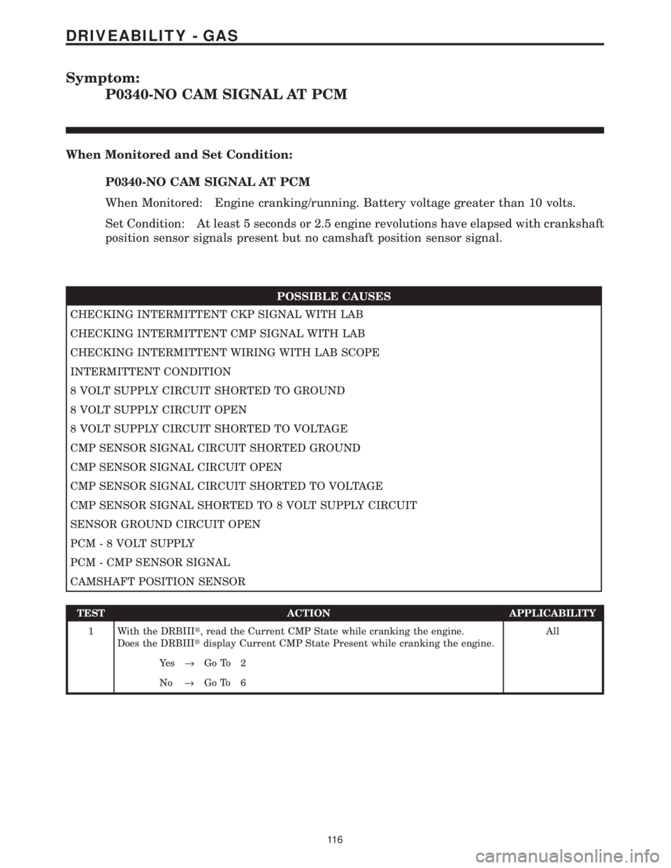
Symptom:
P0340-NO CAM SIGNAL AT PCM
When Monitored and Set Condition:
P0340-NO CAM SIGNAL AT PCM
When Monitored: Engine cranking/running. Battery voltage greater than 10 volts.
Set Condition: At least 5 seconds or 2.5 engine revolutions have elapsed with crankshaft
position sensor signals present but no camshaft position sensor signal.
POSSIBLE CAUSES
CHECKING INTERMITTENT CKP SIGNAL WITH LAB
CHECKING INTERMITTENT CMP SIGNAL WITH LAB
CHECKING INTERMITTENT WIRING WITH LAB SCOPE
INTERMITTENT CONDITION
8 VOLT SUPPLY CIRCUIT SHORTED TO GROUND
8 VOLT SUPPLY CIRCUIT OPEN
8 VOLT SUPPLY CIRCUIT SHORTED TO VOLTAGE
CMP SENSOR SIGNAL CIRCUIT SHORTED GROUND
CMP SENSOR SIGNAL CIRCUIT OPEN
CMP SENSOR SIGNAL CIRCUIT SHORTED TO VOLTAGE
CMP SENSOR SIGNAL SHORTED TO 8 VOLT SUPPLY CIRCUIT
SENSOR GROUND CIRCUIT OPEN
PCM - 8 VOLT SUPPLY
PCM - CMP SENSOR SIGNAL
CAMSHAFT POSITION SENSOR
TEST ACTION APPLICABILITY
1 With the DRBIIIt, read the Current CMP State while cranking the engine.
Does the DRBIIItdisplay Current CMP State Present while cranking the engine.All
Ye s®Go To 2
No®Go To 6
11 6
DRIVEABILITY - GAS
Page 3916 of 4284
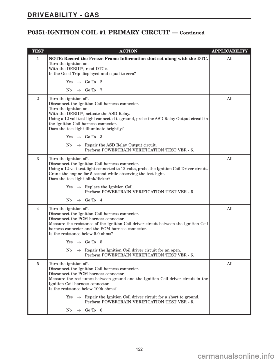
TEST ACTION APPLICABILITY
1NOTE: Record the Freeze Frame Information that set along with the DTC.
Turn the ignition on.
With the DRBIIIt, read DTC's.
Is the Good Trip displayed and equal to zero?All
Ye s®Go To 2
No®Go To 7
2 Turn the ignition off.
Disconnect the Ignition Coil harness connector.
Turn the ignition on.
With the DRBIIIt, actuate the ASD Relay.
Using a 12 volt test light connected to ground, probe the ASD Relay Output circuit in
the Ignition Coil harness connector.
Does the test light illuminate brightly?All
Ye s®Go To 3
No®Repair the ASD Relay Output circuit.
Perform POWERTRAIN VERIFICATION TEST VER - 5.
3 Turn the ignition off.
Disconnect the Ignition Coil harness connector.
Using a 12-volt test light connected to 12-volts, probe the Ignition Coil Driver circuit.
Crank the engine for 5 second while observing the test light.
Does the test light blink/flicker?All
Ye s®Replace the Ignition Coil.
Perform POWERTRAIN VERIFICATION TEST VER - 5.
No®Go To 4
4 Turn the ignition off.
Disconnect the Ignition Coil harness connector.
Disconnect the PCM harness connector.
Measure the resistance of the Ignition Coil driver circuit between the Ignition Coil
harness connector and the PCM harness connector.
Is the resistance below 5.0 ohms?All
Ye s®Go To 5
No®Repair the Ignition Coil driver circuit for an open.
Perform POWERTRAIN VERIFICATION TEST VER - 5.
5 Turn the ignition off.
Disconnect the Ignition Coil harness connector.
Disconnect the PCM harness connector.
Measure the resistance between ground and the Ignition Coil driver circuit in the
Ignition Coil harness connector.
Is the resistance below 100k ohms?All
Ye s®Repair the Ignition Coil driver circuit for a short to ground.
Perform POWERTRAIN VERIFICATION TEST VER - 5.
No®Go To 6
122
DRIVEABILITY - GAS
P0351-IGNITION COIL #1 PRIMARY CIRCUIT ÐContinued
Page 3918 of 4284
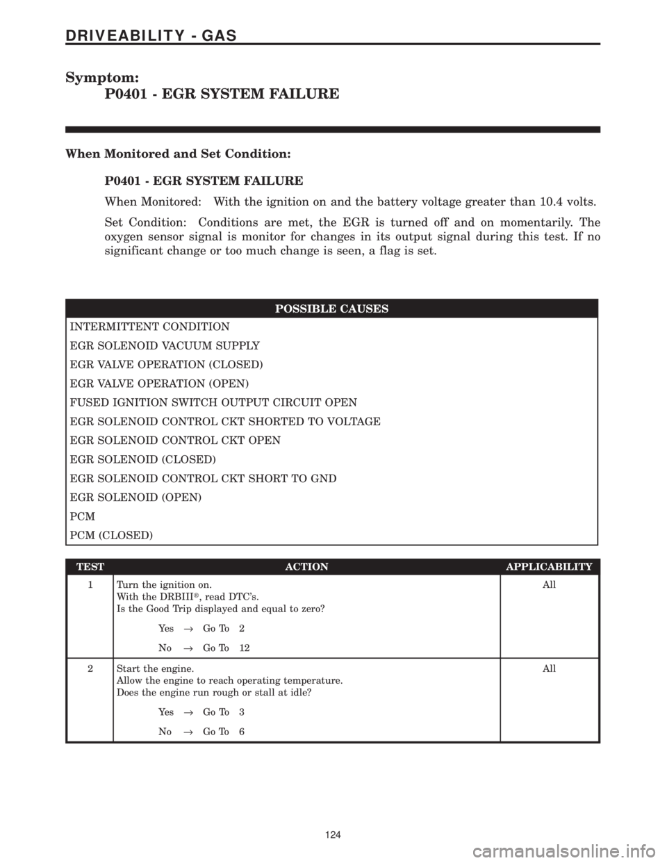
Symptom:
P0401 - EGR SYSTEM FAILURE
When Monitored and Set Condition:
P0401 - EGR SYSTEM FAILURE
When Monitored: With the ignition on and the battery voltage greater than 10.4 volts.
Set Condition: Conditions are met, the EGR is turned off and on momentarily. The
oxygen sensor signal is monitor for changes in its output signal during this test. If no
significant change or too much change is seen, a flag is set.
POSSIBLE CAUSES
INTERMITTENT CONDITION
EGR SOLENOID VACUUM SUPPLY
EGR VALVE OPERATION (CLOSED)
EGR VALVE OPERATION (OPEN)
FUSED IGNITION SWITCH OUTPUT CIRCUIT OPEN
EGR SOLENOID CONTROL CKT SHORTED TO VOLTAGE
EGR SOLENOID CONTROL CKT OPEN
EGR SOLENOID (CLOSED)
EGR SOLENOID CONTROL CKT SHORT TO GND
EGR SOLENOID (OPEN)
PCM
PCM (CLOSED)
TEST ACTION APPLICABILITY
1 Turn the ignition on.
With the DRBIIIt, read DTC's.
Is the Good Trip displayed and equal to zero?All
Ye s®Go To 2
No®Go To 12
2 Start the engine.
Allow the engine to reach operating temperature.
Does the engine run rough or stall at idle?All
Ye s®Go To 3
No®Go To 6
124
DRIVEABILITY - GAS
Page 3922 of 4284
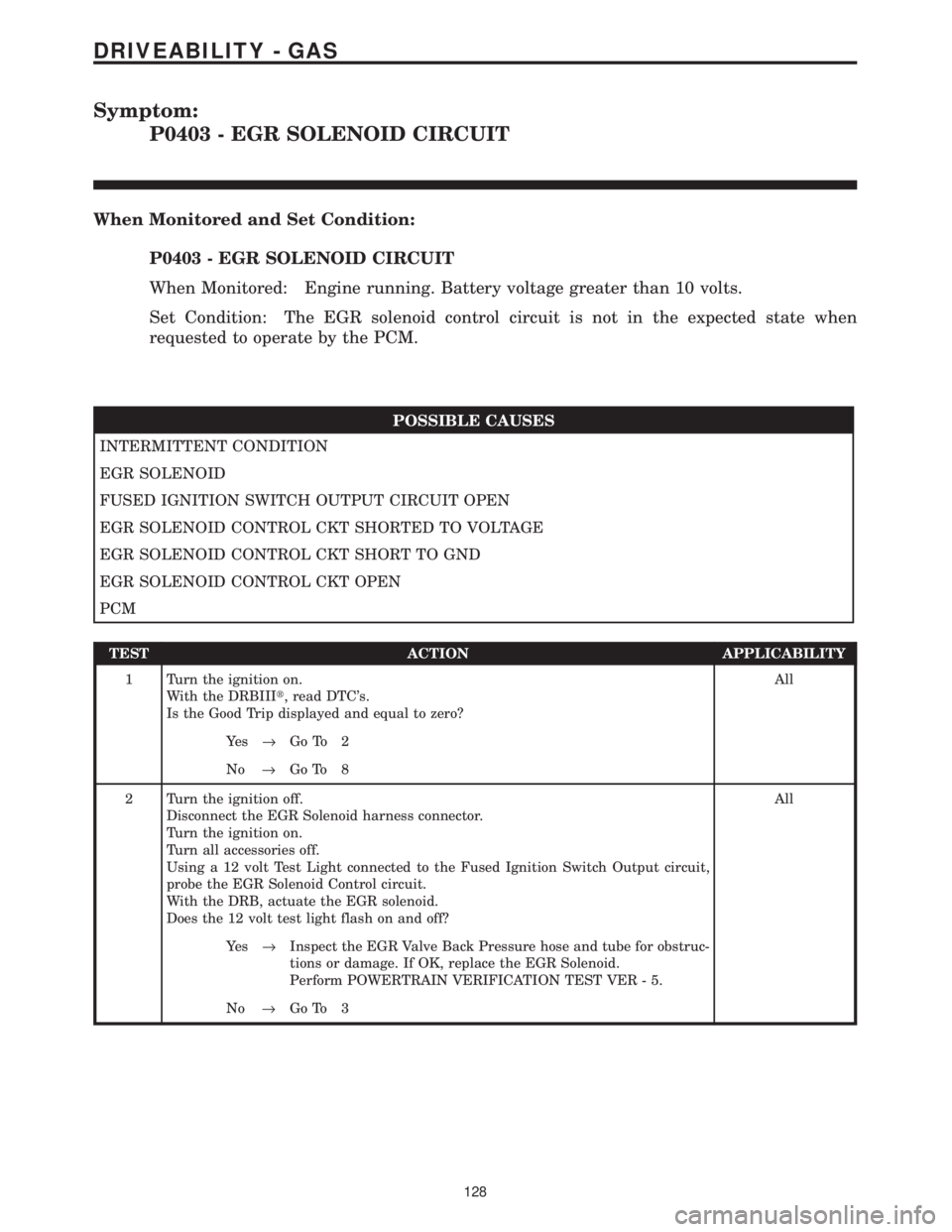
Symptom:
P0403 - EGR SOLENOID CIRCUIT
When Monitored and Set Condition:
P0403 - EGR SOLENOID CIRCUIT
When Monitored: Engine running. Battery voltage greater than 10 volts.
Set Condition: The EGR solenoid control circuit is not in the expected state when
requested to operate by the PCM.
POSSIBLE CAUSES
INTERMITTENT CONDITION
EGR SOLENOID
FUSED IGNITION SWITCH OUTPUT CIRCUIT OPEN
EGR SOLENOID CONTROL CKT SHORTED TO VOLTAGE
EGR SOLENOID CONTROL CKT SHORT TO GND
EGR SOLENOID CONTROL CKT OPEN
PCM
TEST ACTION APPLICABILITY
1 Turn the ignition on.
With the DRBIIIt, read DTC's.
Is the Good Trip displayed and equal to zero?All
Ye s®Go To 2
No®Go To 8
2 Turn the ignition off.
Disconnect the EGR Solenoid harness connector.
Turn the ignition on.
Turn all accessories off.
Using a 12 volt Test Light connected to the Fused Ignition Switch Output circuit,
probe the EGR Solenoid Control circuit.
With the DRB, actuate the EGR solenoid.
Does the 12 volt test light flash on and off?All
Ye s®Inspect the EGR Valve Back Pressure hose and tube for obstruc-
tions or damage. If OK, replace the EGR Solenoid.
Perform POWERTRAIN VERIFICATION TEST VER - 5.
No®Go To 3
128
DRIVEABILITY - GAS
Page 3925 of 4284
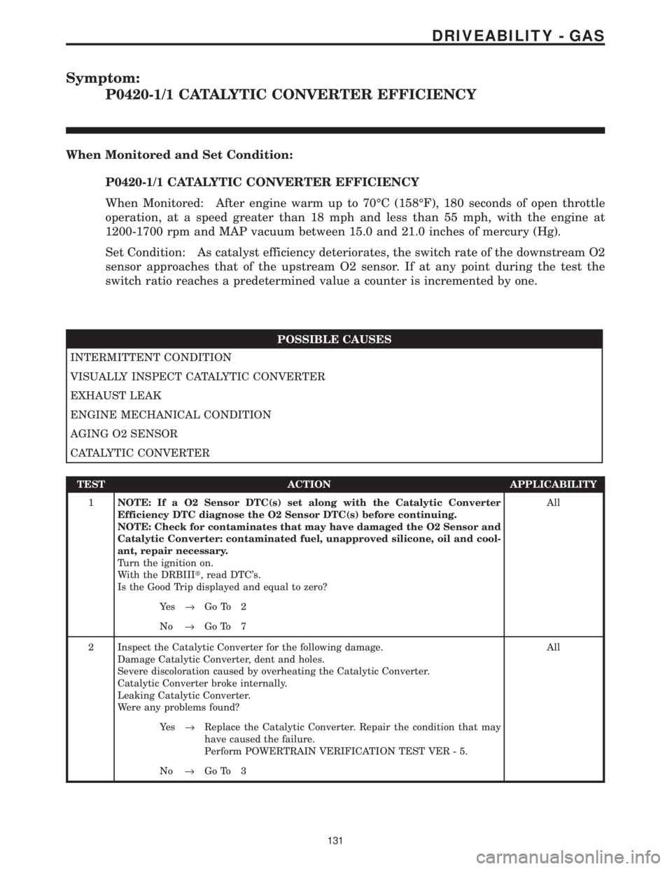
Symptom:
P0420-1/1 CATALYTIC CONVERTER EFFICIENCY
When Monitored and Set Condition:
P0420-1/1 CATALYTIC CONVERTER EFFICIENCY
When Monitored: After engine warm up to 70ÉC (158ÉF), 180 seconds of open throttle
operation, at a speed greater than 18 mph and less than 55 mph, with the engine at
1200-1700 rpm and MAP vacuum between 15.0 and 21.0 inches of mercury (Hg).
Set Condition: As catalyst efficiency deteriorates, the switch rate of the downstream O2
sensor approaches that of the upstream O2 sensor. If at any point during the test the
switch ratio reaches a predetermined value a counter is incremented by one.
POSSIBLE CAUSES
INTERMITTENT CONDITION
VISUALLY INSPECT CATALYTIC CONVERTER
EXHAUST LEAK
ENGINE MECHANICAL CONDITION
AGING O2 SENSOR
CATALYTIC CONVERTER
TEST ACTION APPLICABILITY
1NOTE: If a O2 Sensor DTC(s) set along with the Catalytic Converter
Efficiency DTC diagnose the O2 Sensor DTC(s) before continuing.
NOTE: Check for contaminates that may have damaged the O2 Sensor and
Catalytic Converter: contaminated fuel, unapproved silicone, oil and cool-
ant, repair necessary.
Turn the ignition on.
With the DRBIIIt, read DTC's.
Is the Good Trip displayed and equal to zero?All
Ye s®Go To 2
No®Go To 7
2 Inspect the Catalytic Converter for the following damage.
Damage Catalytic Converter, dent and holes.
Severe discoloration caused by overheating the Catalytic Converter.
Catalytic Converter broke internally.
Leaking Catalytic Converter.
Were any problems found?All
Ye s®Replace the Catalytic Converter. Repair the condition that may
have caused the failure.
Perform POWERTRAIN VERIFICATION TEST VER - 5.
No®Go To 3
131
DRIVEABILITY - GAS
Page 3927 of 4284
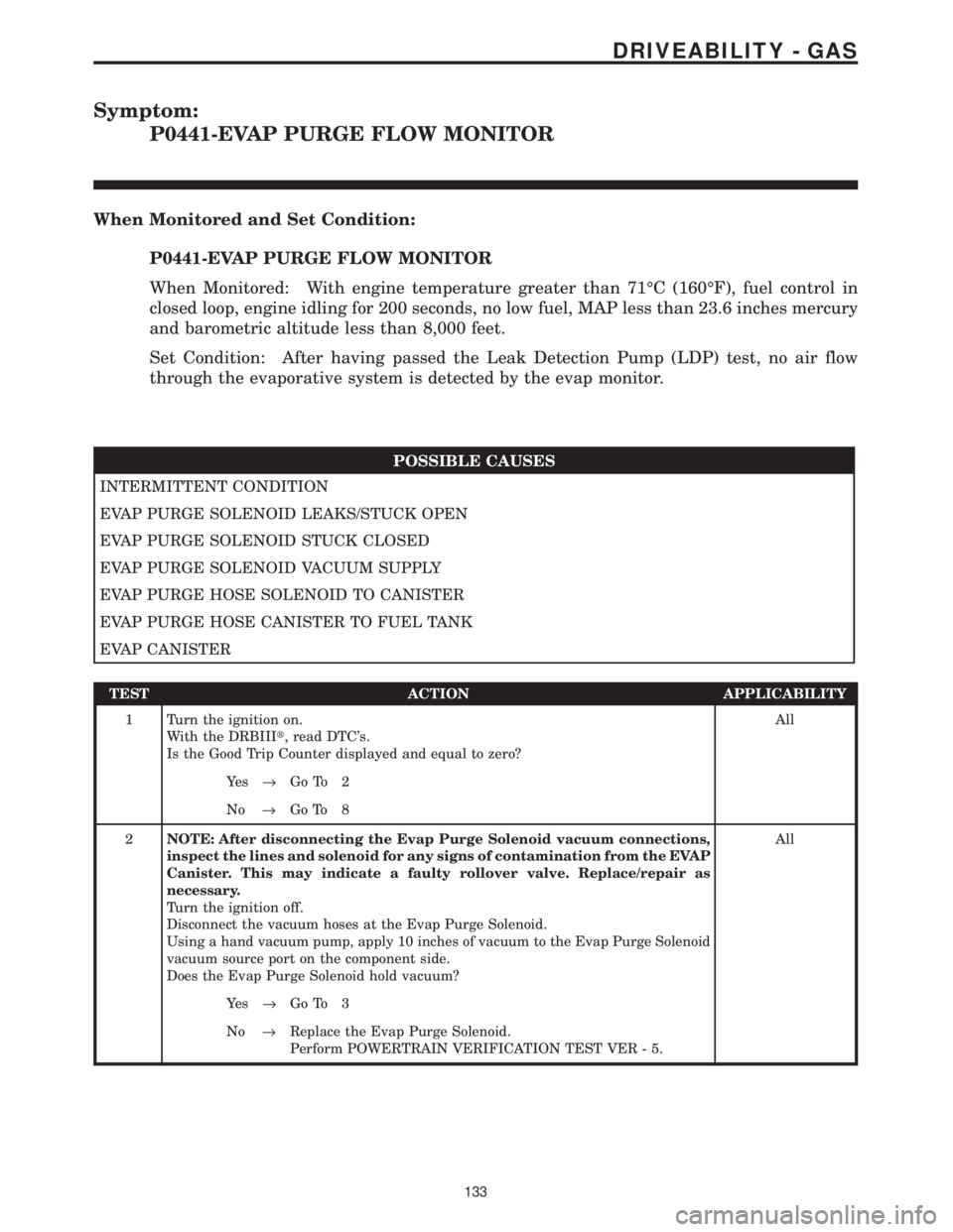
Symptom:
P0441-EVAP PURGE FLOW MONITOR
When Monitored and Set Condition:
P0441-EVAP PURGE FLOW MONITOR
When Monitored: With engine temperature greater than 71ÉC (160ÉF), fuel control in
closed loop, engine idling for 200 seconds, no low fuel, MAP less than 23.6 inches mercury
and barometric altitude less than 8,000 feet.
Set Condition: After having passed the Leak Detection Pump (LDP) test, no air flow
through the evaporative system is detected by the evap monitor.
POSSIBLE CAUSES
INTERMITTENT CONDITION
EVAP PURGE SOLENOID LEAKS/STUCK OPEN
EVAP PURGE SOLENOID STUCK CLOSED
EVAP PURGE SOLENOID VACUUM SUPPLY
EVAP PURGE HOSE SOLENOID TO CANISTER
EVAP PURGE HOSE CANISTER TO FUEL TANK
EVAP CANISTER
TEST ACTION APPLICABILITY
1 Turn the ignition on.
With the DRBIIIt, read DTC's.
Is the Good Trip Counter displayed and equal to zero?All
Ye s®Go To 2
No®Go To 8
2NOTE: After disconnecting the Evap Purge Solenoid vacuum connections,
inspect the lines and solenoid for any signs of contamination from the EVAP
Canister. This may indicate a faulty rollover valve. Replace/repair as
necessary.
Turn the ignition off.
Disconnect the vacuum hoses at the Evap Purge Solenoid.
Using a hand vacuum pump, apply 10 inches of vacuum to the Evap Purge Solenoid
vacuum source port on the component side.
Does the Evap Purge Solenoid hold vacuum?All
Ye s®Go To 3
No®Replace the Evap Purge Solenoid.
Perform POWERTRAIN VERIFICATION TEST VER - 5.
133
DRIVEABILITY - GAS