2001 CHRYSLER VOYAGER display
[x] Cancel search: displayPage 3777 of 4284
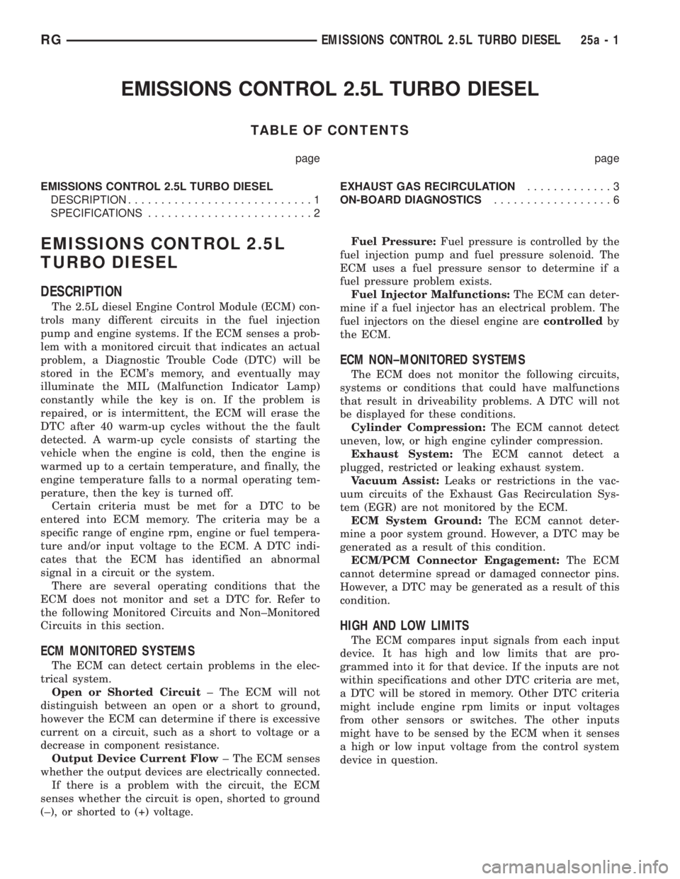
EMISSIONS CONTROL 2.5L TURBO DIESEL
TABLE OF CONTENTS
page page
EMISSIONS CONTROL 2.5L TURBO DIESEL
DESCRIPTION............................1
SPECIFICATIONS.........................2EXHAUST GAS RECIRCULATION.............3
ON-BOARD DIAGNOSTICS..................6
EMISSIONS CONTROL 2.5L
TURBO DIESEL
DESCRIPTION
The 2.5L diesel Engine Control Module (ECM) con-
trols many different circuits in the fuel injection
pump and engine systems. If the ECM senses a prob-
lem with a monitored circuit that indicates an actual
problem, a Diagnostic Trouble Code (DTC) will be
stored in the ECM's memory, and eventually may
illuminate the MIL (Malfunction Indicator Lamp)
constantly while the key is on. If the problem is
repaired, or is intermittent, the ECM will erase the
DTC after 40 warm-up cycles without the the fault
detected. A warm-up cycle consists of starting the
vehicle when the engine is cold, then the engine is
warmed up to a certain temperature, and finally, the
engine temperature falls to a normal operating tem-
perature, then the key is turned off.
Certain criteria must be met for a DTC to be
entered into ECM memory. The criteria may be a
specific range of engine rpm, engine or fuel tempera-
ture and/or input voltage to the ECM. A DTC indi-
cates that the ECM has identified an abnormal
signal in a circuit or the system.
There are several operating conditions that the
ECM does not monitor and set a DTC for. Refer to
the following Monitored Circuits and Non±Monitored
Circuits in this section.
ECM MONITORED SYSTEMS
The ECM can detect certain problems in the elec-
trical system.
Open or Shorted Circuit± The ECM will not
distinguish between an open or a short to ground,
however the ECM can determine if there is excessive
current on a circuit, such as a short to voltage or a
decrease in component resistance.
Output Device Current Flow± The ECM senses
whether the output devices are electrically connected.
If there is a problem with the circuit, the ECM
senses whether the circuit is open, shorted to ground
(±), or shorted to (+) voltage.Fuel Pressure:Fuel pressure is controlled by the
fuel injection pump and fuel pressure solenoid. The
ECM uses a fuel pressure sensor to determine if a
fuel pressure problem exists.
Fuel Injector Malfunctions:The ECM can deter-
mine if a fuel injector has an electrical problem. The
fuel injectors on the diesel engine arecontrolledby
the ECM.
ECM NON±MONITORED SYSTEMS
The ECM does not monitor the following circuits,
systems or conditions that could have malfunctions
that result in driveability problems. A DTC will not
be displayed for these conditions.
Cylinder Compression:The ECM cannot detect
uneven, low, or high engine cylinder compression.
Exhaust System:The ECM cannot detect a
plugged, restricted or leaking exhaust system.
Vacuum Assist:Leaks or restrictions in the vac-
uum circuits of the Exhaust Gas Recirculation Sys-
tem (EGR) are not monitored by the ECM.
ECM System Ground:The ECM cannot deter-
mine a poor system ground. However, a DTC may be
generated as a result of this condition.
ECM/PCM Connector Engagement:The ECM
cannot determine spread or damaged connector pins.
However, a DTC may be generated as a result of this
condition.
HIGH AND LOW LIMITS
The ECM compares input signals from each input
device. It has high and low limits that are pro-
grammed into it for that device. If the inputs are not
within specifications and other DTC criteria are met,
a DTC will be stored in memory. Other DTC criteria
might include engine rpm limits or input voltages
from other sensors or switches. The other inputs
might have to be sensed by the ECM when it senses
a high or low input voltage from the control system
device in question.
RGEMISSIONS CONTROL 2.5L TURBO DIESEL25a-1
Page 3782 of 4284
ON-BOARD DIAGNOSTICS
TABLE OF CONTENTS
page
ON-BOARD DIAGNOSTICS
DESCRIPTION............................6
ON-BOARD DIAGNOSTICS
DESCRIPTION - DIAGNOSTIC TROUBLE CODES
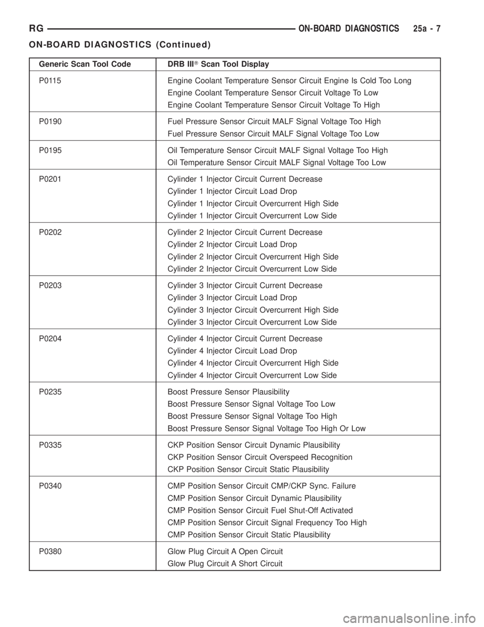
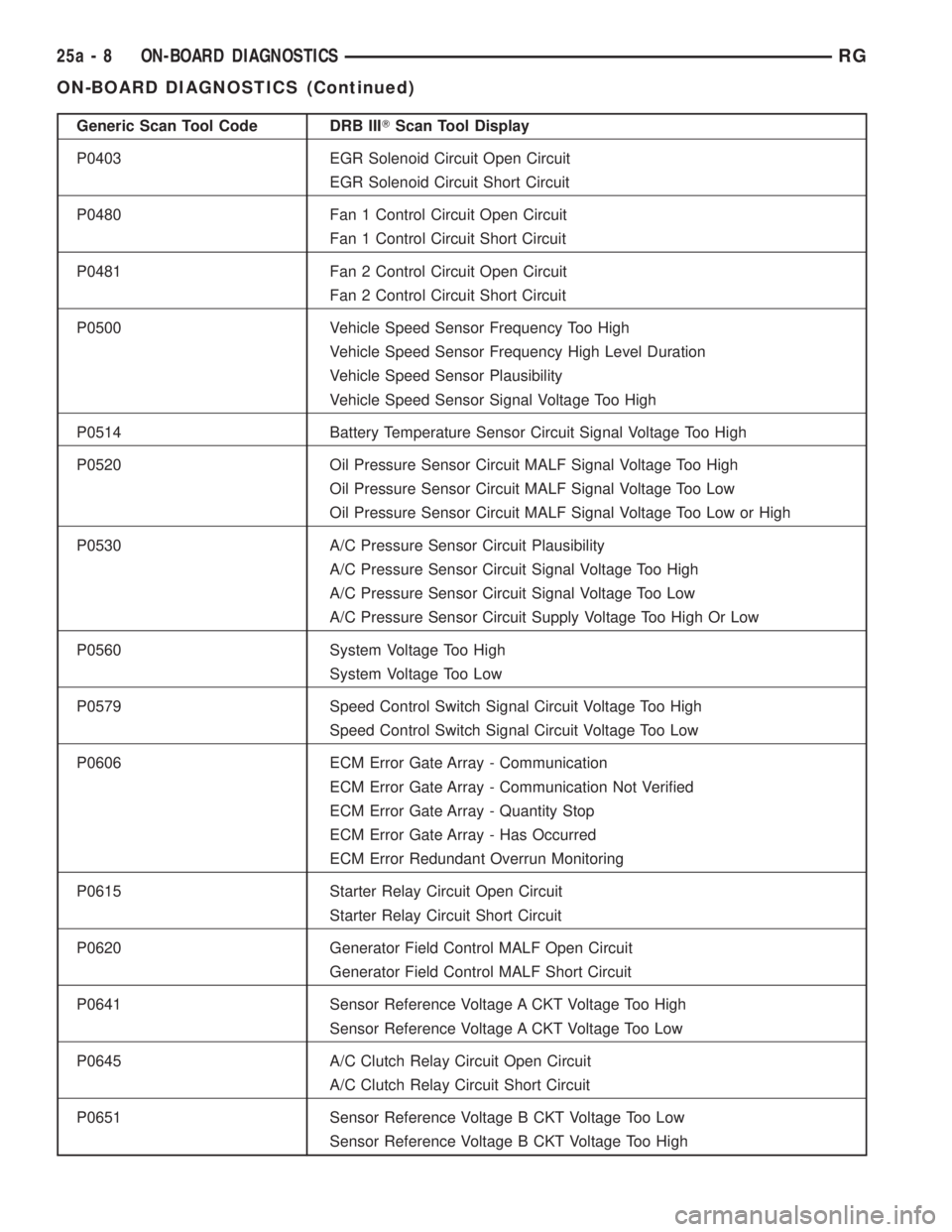
On the following pages, a list of DTC's is provided
for the 2.5L diesel engine. A DTC indicates that the
ECM has recognized an abnormal signal in a circuit
or the system. A DTC may indicate the result of a
failure, but most likely will not identify the failed
component directly. Refer to the appropriate diagnos-
tic manual for more information on diagnosis of trou-
ble codes.
ACCESSING DIAGNOSTIC TROUBLE CODES
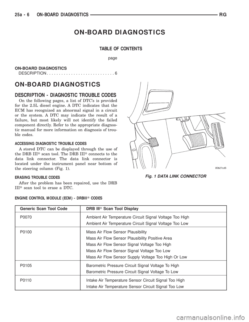
A stored DTC can be displayed through the use of
the DRB IIItscan tool. The DRB IIItconnects to the
data link connector. The data link connector is
located under the instrument panel near bottom of
the steering column (Fig. 1).
ERASING TROUBLE CODES
After the problem has been repaired, use the DRB
IIItscan tool to erase a DTC.
ENGINE CONTROL MODULE (ECM) - DRBIIITCODES
Generic Scan Tool Code DRB IIITScan Tool Display
P0070 Ambient Air Temperature Circuit Signal Voltage Too High
Ambient Air Temperature Circuit Signal Voltage Too Low
P0100 Mass Air Flow Sensor Plausibility
Mass Air Flow Sensor Plausibility Positive Area
Mass Air Flow Sensor Signal Voltage Too High
Mass Air Flow Sensor Signal Voltage Too Low
Mass Air Flow Sensor Supply Voltage Too High Or Low
P0105 Barometric Pressure Circuit Signal Voltage To High
Barometric Pressure Circuit Signal Voltage To Low
P0110 Intake Air Temperature Sensor Circuit Signal Too High
Intake Air Temperature Sensor Circuit Signal Too Low
Fig. 1 DATA LINK CONNECTOR
25a - 6 ON-BOARD DIAGNOSTICSRG
Page 3783 of 4284
Generic Scan Tool Code DRB IIITScan Tool Display
P0115 Engine Coolant Temperature Sensor Circuit Engine Is Cold Too Long
Engine Coolant Temperature Sensor Circuit Voltage To Low
Engine Coolant Temperature Sensor Circuit Voltage To High
P0190 Fuel Pressure Sensor Circuit MALF Signal Voltage Too High
Fuel Pressure Sensor Circuit MALF Signal Voltage Too Low
P0195 Oil Temperature Sensor Circuit MALF Signal Voltage Too High
Oil Temperature Sensor Circuit MALF Signal Voltage Too Low
P0201 Cylinder 1 Injector Circuit Current Decrease
Cylinder 1 Injector Circuit Load Drop
Cylinder 1 Injector Circuit Overcurrent High Side
Cylinder 1 Injector Circuit Overcurrent Low Side
P0202 Cylinder 2 Injector Circuit Current Decrease
Cylinder 2 Injector Circuit Load Drop
Cylinder 2 Injector Circuit Overcurrent High Side
Cylinder 2 Injector Circuit Overcurrent Low Side
P0203 Cylinder 3 Injector Circuit Current Decrease
Cylinder 3 Injector Circuit Load Drop
Cylinder 3 Injector Circuit Overcurrent High Side
Cylinder 3 Injector Circuit Overcurrent Low Side
P0204 Cylinder 4 Injector Circuit Current Decrease
Cylinder 4 Injector Circuit Load Drop
Cylinder 4 Injector Circuit Overcurrent High Side
Cylinder 4 Injector Circuit Overcurrent Low Side
P0235 Boost Pressure Sensor Plausibility
Boost Pressure Sensor Signal Voltage Too Low
Boost Pressure Sensor Signal Voltage Too High
Boost Pressure Sensor Signal Voltage Too High Or Low
P0335 CKP Position Sensor Circuit Dynamic Plausibility
CKP Position Sensor Circuit Overspeed Recognition
CKP Position Sensor Circuit Static Plausibility
P0340 CMP Position Sensor Circuit CMP/CKP Sync. Failure
CMP Position Sensor Circuit Dynamic Plausibility
CMP Position Sensor Circuit Fuel Shut-Off Activated
CMP Position Sensor Circuit Signal Frequency Too High
CMP Position Sensor Circuit Static Plausibility
P0380 Glow Plug Circuit A Open Circuit
Glow Plug Circuit A Short Circuit
RGON-BOARD DIAGNOSTICS25a-7
ON-BOARD DIAGNOSTICS (Continued)
Page 3784 of 4284
Generic Scan Tool Code DRB IIITScan Tool Display
P0403 EGR Solenoid Circuit Open Circuit
EGR Solenoid Circuit Short Circuit
P0480 Fan 1 Control Circuit Open Circuit
Fan 1 Control Circuit Short Circuit
P0481 Fan 2 Control Circuit Open Circuit
Fan 2 Control Circuit Short Circuit
P0500 Vehicle Speed Sensor Frequency Too High
Vehicle Speed Sensor Frequency High Level Duration
Vehicle Speed Sensor Plausibility
Vehicle Speed Sensor Signal Voltage Too High
P0514 Battery Temperature Sensor Circuit Signal Voltage Too High
P0520 Oil Pressure Sensor Circuit MALF Signal Voltage Too High
Oil Pressure Sensor Circuit MALF Signal Voltage Too Low
Oil Pressure Sensor Circuit MALF Signal Voltage Too Low or High
P0530 A/C Pressure Sensor Circuit Plausibility
A/C Pressure Sensor Circuit Signal Voltage Too High
A/C Pressure Sensor Circuit Signal Voltage Too Low
A/C Pressure Sensor Circuit Supply Voltage Too High Or Low
P0560 System Voltage Too High
System Voltage Too Low
P0579 Speed Control Switch Signal Circuit Voltage Too High
Speed Control Switch Signal Circuit Voltage Too Low
P0606 ECM Error Gate Array - Communication
ECM Error Gate Array - Communication Not Verified
ECM Error Gate Array - Quantity Stop
ECM Error Gate Array - Has Occurred
ECM Error Redundant Overrun Monitoring
P0615 Starter Relay Circuit Open Circuit
Starter Relay Circuit Short Circuit
P0620 Generator Field Control MALF Open Circuit
Generator Field Control MALF Short Circuit
P0641 Sensor Reference Voltage A CKT Voltage Too High
Sensor Reference Voltage A CKT Voltage Too Low
P0645 A/C Clutch Relay Circuit Open Circuit
A/C Clutch Relay Circuit Short Circuit
P0651 Sensor Reference Voltage B CKT Voltage Too Low
Sensor Reference Voltage B CKT Voltage Too High
25a - 8 ON-BOARD DIAGNOSTICSRG
ON-BOARD DIAGNOSTICS (Continued)
Page 3785 of 4284
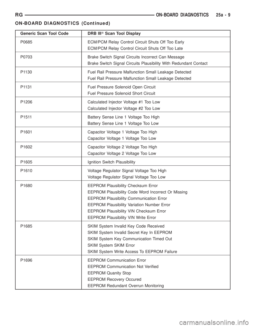
Generic Scan Tool Code DRB IIITScan Tool Display
P0685 ECM/PCM Relay Control Circuit Shuts Off Too Early
ECM/PCM Relay Control Circuit Shuts Off Too Late
P0703 Brake Switch Signal Circuits Incorrect Can Message
Brake Switch Signal Circuits Plausibility With Redundant Contact
P1130 Fuel Rail Pressure Malfunction Small Leakage Detected
Fuel Rail Pressure Malfunction Small Leakage Detected
P1131 Fuel Pressure Solenoid Open Circuit
Fuel Pressure Solenoid Short Circuit
P1206 Calculated Injector Voltage #1 Too Low
Calculated Injector Voltage #2 Too Low
P1511 Battery Sense Line 1 Voltage Too High
Battery Sense Line 1 Voltage Too Low
P1601 Capacitor Voltage 1 Voltage Too High
Capacitor Voltage 1 Voltage Too Low
P1602 Capacitor Voltage 2 Voltage Too High
Capacitor Voltage 2 Voltage Too Low
P1605 Ignition Switch Plausibility
P1610 Voltage Regulator Signal Voltage Too High
Voltage Regulator Signal Voltage Too Low
P1680 EEPROM Plausibility Checksum Error
EEPROM Plausibility Code Word Incorrect Or Missing
EEPROM Plausibility Communication Error
EEPROM Plausibility Variation Number Error
EEPROM Plausibility VIN Checksum Error
EEPROM Plausibility VIN Write Error
P1685 SKIM System Invalid Key Code Received
SKIM System Invalid Secret Key In EEPROM
SKIM System Key Communication Timed Out
SKIM System SKIM Error
SKIM System Write Access To EEPROM Failure
P1696 EEPROM Communication Error
EEPROM Communication Not Verified
EEPROM Quanity Stop
EEPROM Recovery Occured
EEPROM Redundant Overrun Monitoring
RGON-BOARD DIAGNOSTICS25a-9
ON-BOARD DIAGNOSTICS (Continued)
Page 3786 of 4284

Generic Scan Tool Code DRB IIITScan Tool Display
P1703 Brake Switch Signal CKTS Plaus. With Redundant Contact After
Initialization
P2120 Acc. Pedal Position Sensor 1 CKT Plausibility
Acc. Pedal Position Sensor 1 CKT Plausibility With Brake Switch
Acc. Pedal Position Sensor 1 CKT Plausibility With Potentiometer
Acc. Pedal Position Sensor 1 CKT Signal Voltage Too High
Acc. Pedal Position Sensor 1 CKT Signal Voltage Too Low
Acc. Pedal Position Sensor 1 CKT Signal Voltage Too High or Low
25a - 10 ON-BOARD DIAGNOSTICSRG
ON-BOARD DIAGNOSTICS (Continued)
Page 3789 of 4284
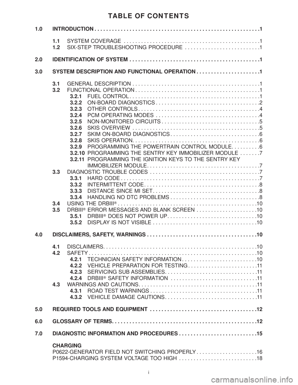
TABLE OF CONTENTS
1.0 INTRODUCTION.........................................................1
1.1SYSTEM COVERAGE...............................................1
1.2SIX-STEP TROUBLESHOOTING PROCEDURE..........................1
2.0 IDENTIFICATION OF SYSTEM.............................................1
3.0 SYSTEM DESCRIPTION AND FUNCTIONAL OPERATION......................1
3.1GENERAL DESCRIPTION............................................1
3.2FUNCTIONAL OPERATION...........................................1
3.2.1FUEL CONTROL.............................................1
3.2.2ON-BOARD DIAGNOSTICS....................................2
3.2.3OTHER CONTROLS..........................................4
3.2.4PCM OPERATING MODES....................................4
3.2.5NON-MONITORED CIRCUITS..................................5
3.2.6SKIS OVERVIEW............................................5
3.2.7SKIM ON-BOARD DIAGNOSTICS...............................6
3.2.8SKIS OPERATION............................................6
3.2.9PROGRAMMING THE POWERTRAIN CONTROL MODULE..........6
3.2.10PROGRAMMING THE SENTRY KEY IMMOBILIZER MODULE.......7
3.2.11PROGRAMMING THE IGNITION KEYS TO THE SENTRY KEY
IMMOBILIZER MODULE.......................................7
3.3DIAGNOSTIC TROUBLE CODES......................................7
3.3.1HARD CODE................................................7
3.3.2INTERMITTENT CODE........................................8
3.3.3DISTANCE SINCE MI SET.....................................8
3.3.4HANDLING NO DTC PROBLEMS...............................8
3.4USING THE DRBIIIT................................................10
3.5DRBIIITERROR MESSAGES AND BLANK SCREEN.....................10
3.5.1DRBIIITDOES NOT POWER UP...............................10
3.5.2DISPLAY IS NOT VISIBLE....................................10
4.0 DISCLAIMERS, SAFETY, WARNINGS......................................10
4.1DISCLAIMERS.....................................................10
4.2SAFETY..........................................................10
4.2.1TECHNICIAN SAFETY INFORMATION..........................10
4.2.2VEHICLE PREPARATION FOR TESTING........................11
4.2.3SERVICING SUB ASSEMBLIES................................11
4.2.4DRBIIITSAFETY INFORMATION..............................11
4.3WARNINGS AND CAUTIONS.........................................11
4.3.1ROAD TEST WARNINGS.....................................11
4.3.2VEHICLE DAMAGE CAUTIONS................................11
5.0 REQUIRED TOOLS AND EQUIPMENT.....................................12
6.0 GLOSSARY OF TERMS..................................................12
7.0 DIAGNOSTIC INFORMATION AND PROCEDURES...........................15
CHARGING
P0622-GENERATOR FIELD NOT SWITCHING PROPERLY.....................16
P1594-CHARGING SYSTEM VOLTAGE TOO HIGH...........................18
i
Page 3795 of 4284
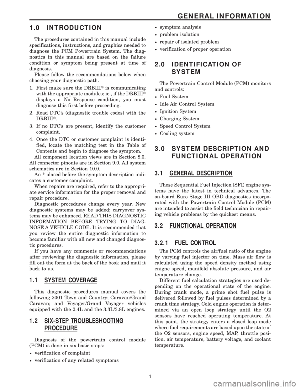
1.0 INTRODUCTION
The procedures contained in this manual include
specifications, instructions, and graphics needed to
diagnose the PCM Powertrain System. The diag-
nostics in this manual are based on the failure
condition or symptom being present at time of
diagnosis.
Please follow the recommendations below when
choosing your diagnostic path.
1. First make sure the DRBIIItis communicating
with the appropriate modules; ie., if the DRBIIIt
displays a No Response condition, you must
diagnose this first before proceeding.
2. Read DTC's (diagnostic trouble codes) with the
DRBIIIt.
3. If no DTC's are present, identify the customer
complaint.
4. Once the DTC or customer complaint is identi-
fied, locate the matching test in the Table of
Contents and begin to diagnose the symptom.
All component location views are in Section 8.0.
All connector pinouts are in Section 9.0. All system
schematics are in Section 10.0.
An * placed before the symptom description indi-
cates a customer complaint.
When repairs are required, refer to the appropri-
ate service information for the proper removal and
repair procedure.
Diagnostic procedures change every year. New
diagnostic systems may be added; carryover sys-
tems may be enhanced. READ THIS DIAGNOSTIC
INFORMATION BEFORE TRYING TO DIAG-
NOSE A VEHICLE CODE. It is recommended that
you review the entire diagnostic information to
become familiar with all new and changed diagnos-
tic procedures.
If you have any comments or recommendations
after reviewing the diagnostic information, please
fill out the form at the back of the book and mail it
back to us.
1.1 SYSTEM COVERAGE
This diagnostic procedures manual covers the
following 2001 Town and Country; Caravan/Grand
Caravan; and Voyager/Grand Voyager vehicles
equipped with the 2.4L and the 3.3L/3.8L engines.
1.2 SIX-STEP TROUBLESHOOTING
PROCEDURE
Diagnosis of the powertrain control module
(PCM) is done in six basic steps:
²verification of complaint
²verification of any related symptoms
²symptom analysis
²problem isolation
²repair of isolated problem
²verification of proper operation
2.0 IDENTIFICATION OF
SYSTEM
The Powertrain Control Module (PCM) monitors
and controls:
²Fuel System
²Idle Air Control System
²Ignition System
²Charging System
²Speed Control System
²Cooling system
3.0 SYSTEM DESCRIPTION AND
FUNCTIONAL OPERATION
3.1 GENERAL DESCRIPTION
These Sequential Fuel Injection (SFI) engine sys-
tems have the latest in technical advances. The
on-board Euro Stage III OBD diagnostics incorpo-
rated with the Powertrain Control Module (PCM)
are intended to assist the field technician in repair-
ing vehicle problems by the quickest means.
3.2 FUNCTIONAL OPERATION
3.2.1 FUEL CONTROL
The PCM controls the air/fuel ratio of the engine
by varying fuel injector on time. Mass air flow is
calculated using the speed density method using
enigne speed, manifold absolute pressure, and air
temperature change.
Different fuel calculation strategies are used de-
pending on the operational state of the engine.
During crank mode, a prime shot fuel pulse is
delivered followed by fuel pulses determined by a
crank time strategy. Cold engine operation is deter-
mined via an open loop strategy until the O2
sensors have reached operating temperature. At
this point, the strategy enters a closed loop mode
where fuel requirements are based upon the state of
the O2 sensors, engine speed, MAP, throttle posi-
tion, air temperature, battery voltage, and coolant
temperature.
1
GENERAL INFORMATION