2001 CHRYSLER VOYAGER display
[x] Cancel search: displayPage 3829 of 4284
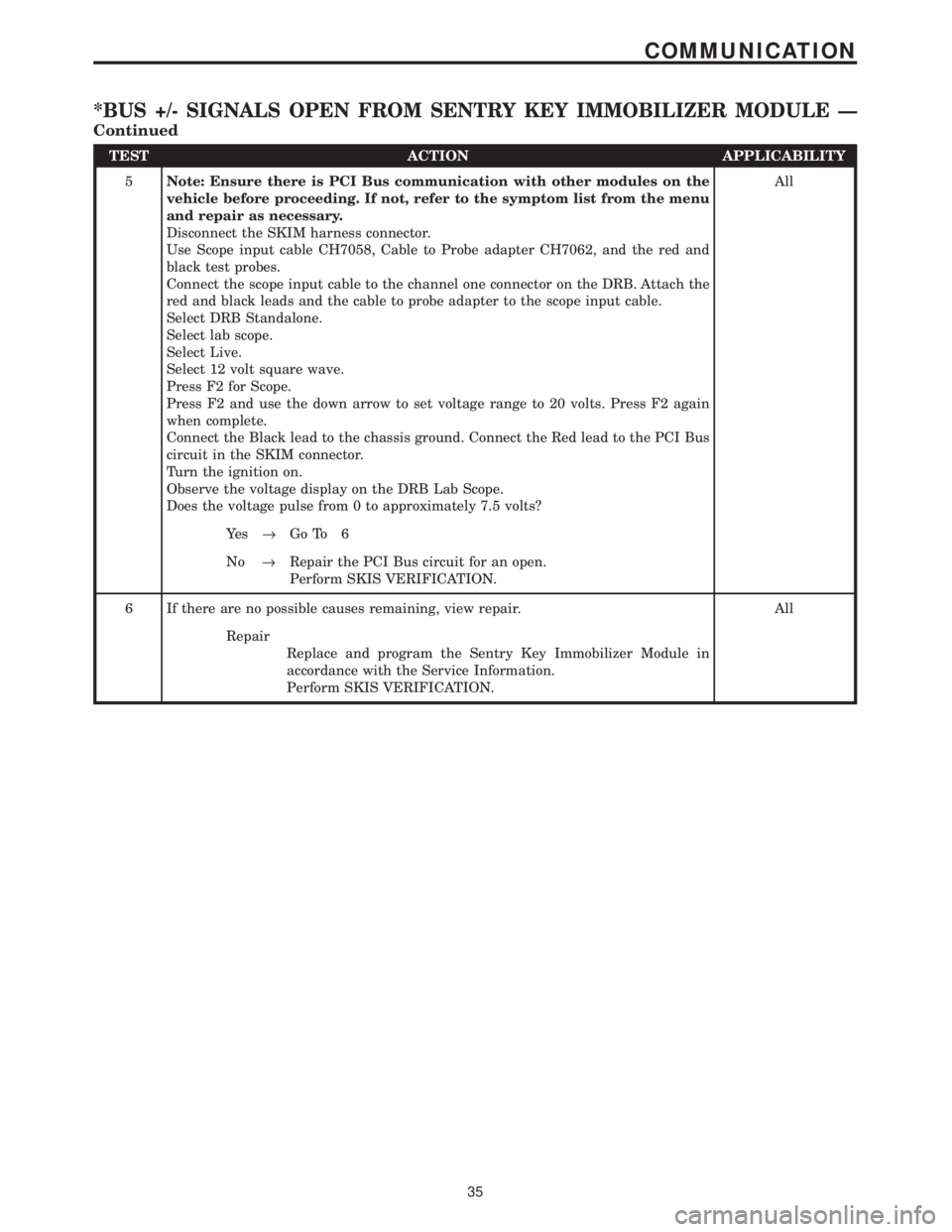
TEST ACTION APPLICABILITY
5Note: Ensure there is PCI Bus communication with other modules on the
vehicle before proceeding. If not, refer to the symptom list from the menu
and repair as necessary.
Disconnect the SKIM harness connector.
Use Scope input cable CH7058, Cable to Probe adapter CH7062, and the red and
black test probes.
Connect the scope input cable to the channel one connector on the DRB. Attach the
red and black leads and the cable to probe adapter to the scope input cable.
Select DRB Standalone.
Select lab scope.
Select Live.
Select 12 volt square wave.
Press F2 for Scope.
Press F2 and use the down arrow to set voltage range to 20 volts. Press F2 again
when complete.
Connect the Black lead to the chassis ground. Connect the Red lead to the PCI Bus
circuit in the SKIM connector.
Turn the ignition on.
Observe the voltage display on the DRB Lab Scope.
Does the voltage pulse from 0 to approximately 7.5 volts?All
Ye s®Go To 6
No®Repair the PCI Bus circuit for an open.
Perform SKIS VERIFICATION.
6 If there are no possible causes remaining, view repair. All
Repair
Replace and program the Sentry Key Immobilizer Module in
accordance with the Service Information.
Perform SKIS VERIFICATION.
35
COMMUNICATION
*BUS +/- SIGNALS OPEN FROM SENTRY KEY IMMOBILIZER MODULE Ð
Continued
Page 3830 of 4284
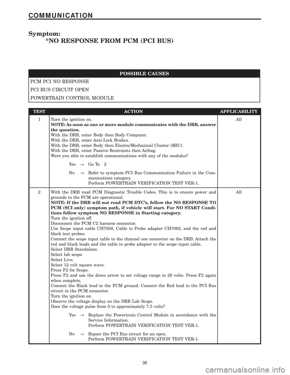
Symptom:
*NO RESPONSE FROM PCM (PCI BUS)
POSSIBLE CAUSES
PCM PCI NO RESPONSE
PCI BUS CIRCUIT OPEN
POWERTRAIN CONTROL MODULE
TEST ACTION APPLICABILITY
1 Turn the ignition on.
NOTE: As soon as one or more module communicates with the DRB, answer
the question.
With the DRB, enter Body then Body Computer.
With the DRB, enter Anti-Lock Brakes.
With the DRB, enter Body then Electro/Mechanical Cluster (MIC).
With the DRB, enter Passive Restraints then Airbag.
Were you able to establish communications with any of the modules?All
Ye s®Go To 2
No®Refer to symptom PCI Bus Communication Failure in the Com-
munications category.
Perform POWERTRAIN VERIFICATION TEST VER-1.
2 With the DRB read PCM Diagnostic Trouble Codes. This is to ensure power and
grounds to the PCM are operational.
NOTE: If the DRB will not read PCM DTC's, follow the NO RESPONSE TO
PCM (SCI only) symptom path, if vehicle will start. For NO START Condi-
tions follow symptom NO RESPONSE in Starting category.
Turn the ignition off.
Disconnect the PCM C2 harness connector.
Use Scope input cable CH7058, Cable to Probe adapter CH7062, and the red and
black test probes.
Connect the scope input cable to the channel one connector on the DRB. Attach the
red and black leads and the cable to probe adapter to the scope input cable.
Select DRB Standalone.
Select lab scope.
Select Live.
Select 12 volt square wave.
Press F2 for Scope.
Press F2 and use the down arrow to set voltage range to 20 volts. Press F2 again
when complete.
Connect the Black lead to the PCM ground. Connect the Red lead to the PCI Bus
circuit in the PCM connector.
Turn the ignition on.
Observe the voltage display on the DRB Lab Scope.
Does the voltage pulse from 0 to approximately 7.5 volts?All
Ye s®Replace the Powertrain Control Module in accordance with the
Service Information.
Perform POWERTRAIN VERIFICATION TEST VER-1.
No®Repair the PCI Bus circuit for an open.
Perform POWERTRAIN VERIFICATION TEST VER-1.
36
COMMUNICATION
Page 3835 of 4284
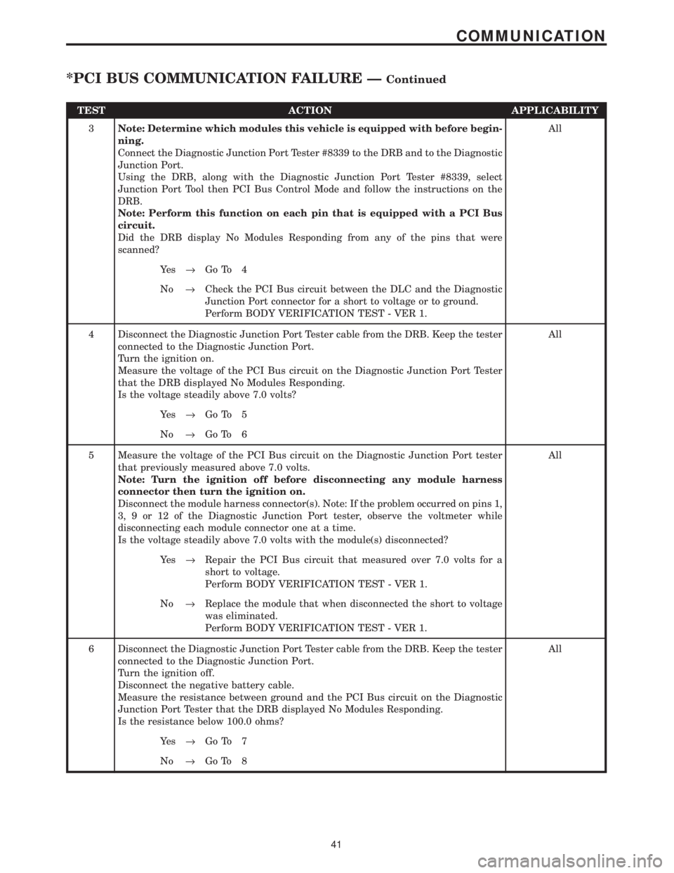
TEST ACTION APPLICABILITY
3Note: Determine which modules this vehicle is equipped with before begin-
ning.
Connect the Diagnostic Junction Port Tester #8339 to the DRB and to the Diagnostic
Junction Port.
Using the DRB, along with the Diagnostic Junction Port Tester #8339, select
Junction Port Tool then PCI Bus Control Mode and follow the instructions on the
DRB.
Note: Perform this function on each pin that is equipped with a PCI Bus
circuit.
Did the DRB display No Modules Responding from any of the pins that were
scanned?All
Ye s®Go To 4
No®Check the PCI Bus circuit between the DLC and the Diagnostic
Junction Port connector for a short to voltage or to ground.
Perform BODY VERIFICATION TEST - VER 1.
4 Disconnect the Diagnostic Junction Port Tester cable from the DRB. Keep the tester
connected to the Diagnostic Junction Port.
Turn the ignition on.
Measure the voltage of the PCI Bus circuit on the Diagnostic Junction Port Tester
that the DRB displayed No Modules Responding.
Is the voltage steadily above 7.0 volts?All
Ye s®Go To 5
No®Go To 6
5 Measure the voltage of the PCI Bus circuit on the Diagnostic Junction Port tester
that previously measured above 7.0 volts.
Note: Turn the ignition off before disconnecting any module harness
connector then turn the ignition on.
Disconnect the module harness connector(s). Note: If the problem occurred on pins 1,
3, 9 or 12 of the Diagnostic Junction Port tester, observe the voltmeter while
disconnecting each module connector one at a time.
Is the voltage steadily above 7.0 volts with the module(s) disconnected?All
Ye s®Repair the PCI Bus circuit that measured over 7.0 volts for a
short to voltage.
Perform BODY VERIFICATION TEST - VER 1.
No®Replace the module that when disconnected the short to voltage
was eliminated.
Perform BODY VERIFICATION TEST - VER 1.
6 Disconnect the Diagnostic Junction Port Tester cable from the DRB. Keep the tester
connected to the Diagnostic Junction Port.
Turn the ignition off.
Disconnect the negative battery cable.
Measure the resistance between ground and the PCI Bus circuit on the Diagnostic
Junction Port Tester that the DRB displayed No Modules Responding.
Is the resistance below 100.0 ohms?All
Ye s®Go To 7
No®Go To 8
41
COMMUNICATION
*PCI BUS COMMUNICATION FAILURE ÐContinued
Page 3837 of 4284
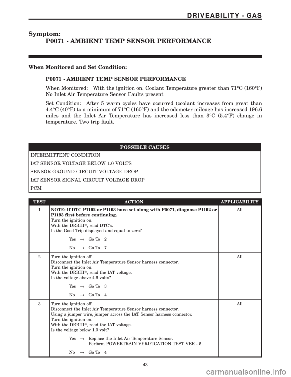
Symptom:
P0071 - AMBIENT TEMP SENSOR PERFORMANCE
When Monitored and Set Condition:
P0071 - AMBIENT TEMP SENSOR PERFORMANCE
When Monitored: With the ignition on. Coolant Temperature greater than 71ÉC (160ÉF)
No Inlet Air Temperature Sensor Faults present
Set Condition: After 5 warm cycles have occurred (coolant increases from great than
4.4ÉC (40ÉF) to a minimum of 71ÉC (160ÉF) and the odometer mileage has increased 196.6
miles and the Inlet Air Temperature has increased less than 3ÉC (5.4ÉF) change in
temperature. Two trip fault.
POSSIBLE CAUSES
INTERMITTENT CONDITION
IAT SENSOR VOLTAGE BELOW 1.0 VOLTS
SENSOR GROUND CIRCUIT VOLTAGE DROP
IAT SENSOR SIGNAL CIRCUIT VOLTAGE DROP
PCM
TEST ACTION APPLICABILITY
1NOTE: If DTC P1192 or P1193 have set along with P0071, diagnose P1192 or
P1193 first before continuing.
Turn the ignition on.
With the DRBIIIt, read DTC's.
Is the Good Trip displayed and equal to zero?All
Ye s®Go To 2
No®Go To 7
2 Turn the ignition off.
Disconnect the Inlet Air Temperature Sensor harness connector.
Turn the ignition on.
With the DRBIIIt, read the IAT voltage.
Is the voltage above 4.6 volts?All
Ye s®Go To 3
No®Go To 4
3 Turn the ignition off.
Disconnect the Inlet Air Temperature Sensor harness connector.
Using a jumper wire, jumper across the IAT Sensor harness connector.
Turn the ignition on.
With the DRBIIIt, read the IAT voltage.
Is the voltage below 1.0 volt?All
Ye s®Replace the Inlet Air Temperature Sensor.
Perform POWERTRAIN VERIFICATION TEST VER - 5.
No®Go To 4
43
DRIVEABILITY - GAS
Page 3853 of 4284
Symptom:
P0121-TPS VOLTAGE DOES NOT AGREE WITH MAP
When Monitored and Set Condition:
P0121-TPS VOLTAGE DOES NOT AGREE WITH MAP
When Monitored: With the engine running and no MAP Sensor or TP Sensor DTC's set.
Engine speed must be greater than 1600 RPM.
Set Condition: When the manifold vacuum is low, the TP sensor signal should be high.
Conversely, when manifold vacuum is high, the TP sensor signal should be low. If the MAP
Sensor and TP Sensor do not respond within 4 seconds as stated above, a DTC will be set.
POSSIBLE CAUSES
INTERMITTENT CONDITION
HIGH RESISTANCE IN 5 VOLT SUPPLY CIRCUIT
HIGH RESISTANCE TO GROUND IN 5 VOLT SUPPLY CIRCUIT
MAP SENSOR
HIGH RESISTANCE IN MAP SENSOR SIGNAL CIRCUIT
HIGH RESISTANCE TO GROUND IN MAP SENSOR SIGNAL CIRCUIT
HIGH RESISTANCE IN SENSOR GROUND CIRCUIT
PCM
HIGH RESISTANCE IN 5 VOLT SUPPLY CIRCUIT
HIGH RESISTANCE TO GROUND IN 5 VOLT SUPPLY CIRCUIT
TP SENSOR
HIGH RESISTANCE IN TP SENSOR SIGNAL CIRCUIT
HIGH RESISTANCE TO GROUND IN THROTTLE POSITION SENSOR SIGNAL CIRCUIT
HIGH RESISTANCE IN SENSOR GROUND CIRCUIT
PCM
TEST ACTION APPLICABILITY
1NOTE: Diagnose any TP Sensor or MAP Sensor component DTC first before
continuing.
NOTE: If the P0500 - No Vehicle Speed Signal is set long with this DTC, refer
to the P0500 diagnostics before continuing.
NOTE: The throttle plate and linkage should be free from binding and
carbon build up.
NOTE: Ensure the throttle plate is at the idle position.
Turn the ignition on.
With the DRBIIIt, read DTC's.
Is the Good Trip displayed and equal to zero?All
Ye s®Go To 2
No®Go To 18
59
DRIVEABILITY - GAS
Page 3854 of 4284
TEST ACTION APPLICABILITY
2 Start the engine.
With the DRBIIIt, monitor the MAP Sensor voltage.
Snap the throttle.
Is the MAP Sensor voltage from below 2.0 volts at idle to above 3.5 volts wide open
throttle?All
Ye s®Go To 3
No®Go To 11
3 Turn the ignition on.
With the DRBIIIt, monitor the TP Sensor voltage while slowly depressing the
throttle pedal from the idle position to the wide open throttle position.
Does voltage start approximately 0.8 volts and go above 3.5 volts with a smooth
voltage change?All
Ye s®Go To 18
No®Go To 4
4 Turn the ignition off.
Disconnect the TP Sensor harness connector.
Disconnect the PCM harness connector.
Measure the resistance of the 5 Volt Supply circuit from the TP Sensor harness
connector to the PCM harness connector.
Is the resistance below 5.0 ohms?All
Ye s®Go To 5
No®Repair the 5 Volt Supply circuit for high resistance.
Perform POWERTRAIN VERIFICATION TEST VER - 5.
5 Turn the ignition off.
Disconnect the TP Sensor harness connector.
Disconnect the PCM harness connector.
Measure the resistance of the 5 Volt Supply circuit from the TP Sensor harness
connector to ground.
Is the resistance above 100k ohms?All
Ye s®Go To 6
No®Repair the 5 Volt Supply circuit for high resistance to ground.
Perform POWERTRAIN VERIFICATION TEST VER - 5.
6 Turn the ignition off.
Disconnect the TP Sensor harness connector.
With the DRBIIIt, monitor the TP Sensor voltage.
Turn the ignition on.
Connect a jumper wire between the TP Sensor Signal circuit and the Sensor ground
circuit .
Does the DRBIIItdisplay TP voltage from approximately 4.9 volts to below 0.5 volt?All
Ye s®Replace the Throttle Position Sensor.
Perform POWERTRAIN VERIFICATION TEST VER - 5.
No®Go To 7
60
DRIVEABILITY - GAS
P0121-TPS VOLTAGE DOES NOT AGREE WITH MAP ÐContinued
Page 3856 of 4284
TEST ACTION APPLICABILITY
12 Turn the ignition off.
Disconnect the MAP Sensor harness connector.
Disconnect the PCM harness connector.
Measure the resistance of the 5 Volt Supply circuit from the MAP Sensor harness
connector to ground.
Is the resistance above 100k ohms?All
Ye s®Go To 13
No®Repair the 5 Volt Supply circuit for high resistance to ground.
Perform POWERTRAIN VERIFICATION TEST VER - 5.
13 Turn the ignition off.
Disconnect the MAP Sensor harness connector.
With the DRBIIIt, monitor the MAP Sensor voltage.
Turn the ignition on.
Connect a jumper wire between the MAP Sensor Signal circuit and the Sensor
ground circuit .
Cycle the ignition switch from off to on.
With the DRBIIIt, monitor the MAP Sensor voltage.
Does the DRBIIItdisplay MAP voltage from approximately 4.9 volts to below 0.5
volt?All
Ye s®Replace the MAP Sensor.
Perform POWERTRAIN VERIFICATION TEST VER - 5.
No®Go To 14
14 Turn the ignition off.
Disconnect the MAP Sensor harness connector.
Disconnect the PCM harness connector.
Measure the resistance of the MAP Sensor Signal circuit from the MAP Sensor
harness connector to the PCM harness connector.
Is the resistance below 5.0 ohms?All
Ye s®Go To 15
No®Repair the MAP Sensor Signal circuit for high resistance.
Perform POWERTRAIN VERIFICATION TEST VER - 5.
15 Turn the ignition off.
Disconnect the MAP Sensor harness connector.
Disconnect the PCM harness connector.
Measure the resistance of the MAP Sensor Signal circuit from the MAP Sensor
harness connector to ground.
Is the resistance above 100k ohms?All
Ye s®Go To 16
No®Repair the MAP Sensor Signal circuit for high resistance to
ground.
Perform POWERTRAIN VERIFICATION TEST VER - 5.
62
DRIVEABILITY - GAS
P0121-TPS VOLTAGE DOES NOT AGREE WITH MAP ÐContinued
Page 3873 of 4284
Symptom List:
P0133-1/1 O2 SENSOR SLOW RESPONSE
P0139-1/2 O2 SENSOR SLOW RESPONSE
Test Note: All symptoms listed above are diagnosed using the same tests.
The title for the tests will be P0133-1/1 O2 SENSOR SLOW
RESPONSE.
When Monitored and Set Condition:
P0133-1/1 O2 SENSOR SLOW RESPONSE
When Monitored: Start and drive vehicle greater than 10 MPH with throttle open for a
minimum 200 seconds. Coolant greater than 70ÉC (158ÉF). EVAP Purge is active. Test
performs in idle drive.
Set Condition: The oxygen sensor signal voltage is switching from below 0.39 volts to
above 0.58 volts and back fewer times than required in 60 seconds. Two trip fault..
P0139-1/2 O2 SENSOR SLOW RESPONSE
When Monitored: Start engine. Allow engine to idle. For 1st part of test, if limits are
exceeded, test passes. If not, 2nd part of test runs. Engine running for grater than 295
seconds. amb/batt temp >44ÉF, Baro >22.139HG, MAP >13.8 & <21.69HG, RPM >1400 &
<2500 (4cylinder) RPM > 1120 & <1950(6 cylinder) and vss >22 and < 60 MPH.
Set Condition: The oxygen sensor signal voltage is has not switched below 0.35 volts to
above 0.53 volts in 411 seconds of engine run. Two trip fault.
POSSIBLE CAUSES
INTERMITTENT CONDITION
EXHAUST LEAK
O2 SENSOR SIGNAL CIRCUIT VOLTAGE DROP
O2 SENSOR GROUND CIRCUIT VOLTAGE DROP
O2 SENSOR
TEST ACTION APPLICABILITY
1NOTE: Check for contaminates that may have damaged the O2 Sensor:
contaminated fuel, unapproved silicone, oil and coolant.
Turn the ignition on.
With the DRBIIIt, read DTC's.
Is the Good Trip displayed and equal to zero?All
Ye s®Go To 2
No®Go To 6
79
DRIVEABILITY - GAS