2001 CHRYSLER VOYAGER relay
[x] Cancel search: relayPage 2874 of 4284
The fuel filter is replaceable, it is mounted on the
outside and on top of the fuel tank. Refer to the
Maintenance Schedules in the Introduction section of
this manual for recommended fuel filter replacement
intervals.
FFV REPLACEMENT PARTS
Many components in a Flexible Fuel Vehicle (FFV)
are designed to be compatible with ethanol. Always
be sure that the vehicle is serviced with correct etha-
nol compatible parts.
CAUTION: Replacing fuel system components with
non-ethanol compatible components can damage
your vehicle and may void the warranty.
OPERATION
The fuel system is provided fuel pressure by an in-
tank pump module. The PCM controls the operation
of the fuel system by providing battery voltage to the
fuel pump through the fuel pump relay. The PCM
requires only three inputs and a good ground to oper-
ate the fuel pump relay. The three inputs are:
²Ignition voltage
²Crankshaft Position (CKP) sensor
²Camshaft Position (CMP) sensor
DIAGNOSIS AND TESTING - FUEL DELIVERY
SYSTEM
(Refer to Appropriate Diagnositic Information)
STANDARD PROCEDURE - FUEL SYSTEM
PRESSURE RELEASE PROCEDURE
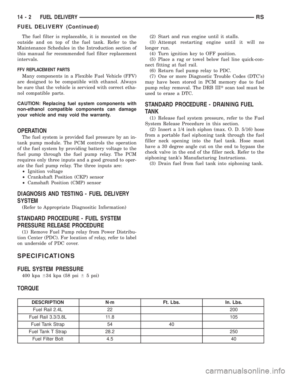
(1) Remove Fuel Pump relay from Power Distribu-
tion Center (PDC). For location of relay, refer to label
on underside of PDC cover.(2) Start and run engine until it stalls.
(3) Attempt restarting engine until it will no
longer run.
(4) Turn ignition key to OFF position.
(5) Place a rag or towel below fuel line quick-con-
nect fitting at fuel rail.
(6) Return fuel pump relay to PDC.
(7) One or more Diagnostic Trouble Codes (DTC's)
may have been stored in PCM memory due to fuel
pump relay removal. The DRB IIItscan tool must be
used to erase a DTC.
STANDARD PROCEDURE - DRAINING FUEL
TANK
(1) Release fuel system pressure, refer to the Fuel
System Release Procedure in this section.
(2) Insert a 1/4 inch siphon (max. O. D. 5/16) hose
from a portable fuel siphoning tank through the fuel
filler neck opening into the fuel tank. Hose most
have a 30 degree angle cut on the end to bypass the
check valve in the end of the filler neck. Refer to the
siphoning tank's Manufacturing Instructions.
(3) Drain fuel from fuel tank into siphoning tank.
SPECIFICATIONS
FUEL SYSTEM PRESSURE
400 kpa634 kpa (58 psi65 psi)
TORQUE
DESCRIPTION N´m Ft. Lbs. In. Lbs.
Fuel Rail 2.4L 22 200
Fuel Rail 3.3/3.8L 11.8 105
Fuel Tank Strap 54 40
Fuel Tank T Strap 28.2 250
Fuel Filter Bolt 4.5 40
14 - 2 FUEL DELIVERYRS
FUEL DELIVERY (Continued)
Page 2879 of 4284
The pressure regulator is a mechanical device that
is NOT controlled by the PCM or engine vacuum.
REMOVAL
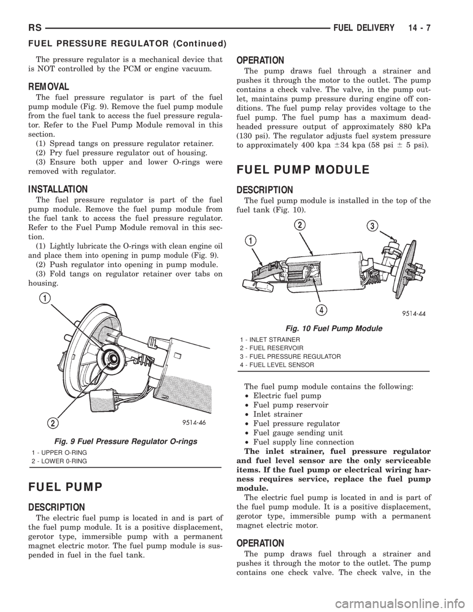
The fuel pressure regulator is part of the fuel
pump module (Fig. 9). Remove the fuel pump module
from the fuel tank to access the fuel pressure regula-
tor. Refer to the Fuel Pump Module removal in this
section.
(1) Spread tangs on pressure regulator retainer.
(2) Pry fuel pressure regulator out of housing.
(3) Ensure both upper and lower O-rings were
removed with regulator.
INSTALLATION
The fuel pressure regulator is part of the fuel
pump module. Remove the fuel pump module from
the fuel tank to access the fuel pressure regulator.
Refer to the Fuel Pump Module removal in this sec-
tion.
(1)
Lightly lubricate the O-rings with clean engine oil
and place them into opening in pump module (Fig. 9).
(2) Push regulator into opening in pump module.
(3) Fold tangs on regulator retainer over tabs on
housing.
FUEL PUMP
DESCRIPTION
The electric fuel pump is located in and is part of
the fuel pump module. It is a positive displacement,
gerotor type, immersible pump with a permanent
magnet electric motor. The fuel pump module is sus-
pended in fuel in the fuel tank.
OPERATION
The pump draws fuel through a strainer and
pushes it through the motor to the outlet. The pump
contains a check valve. The valve, in the pump out-
let, maintains pump pressure during engine off con-
ditions. The fuel pump relay provides voltage to the
fuel pump. The fuel pump has a maximum dead-
headed pressure output of approximately 880 kPa
(130 psi). The regulator adjusts fuel system pressure
to approximately 400 kpa634 kpa (58 psi65 psi).
FUEL PUMP MODULE
DESCRIPTION
The fuel pump module is installed in the top of the
fuel tank (Fig. 10).
The fuel pump module contains the following:
²Electric fuel pump
²Fuel pump reservoir
²Inlet strainer
²Fuel pressure regulator
²Fuel gauge sending unit
²Fuel supply line connection
The inlet strainer, fuel pressure regulator
and fuel level sensor are the only serviceable
items. If the fuel pump or electrical wiring har-
ness requires service, replace the fuel pump
module.
The electric fuel pump is located in and is part of
the fuel pump module. It is a positive displacement,
gerotor type, immersible pump with a permanent
magnet electric motor.
OPERATION
The pump draws fuel through a strainer and
pushes it through the motor to the outlet. The pump
contains one check valve. The check valve, in the
Fig. 9 Fuel Pressure Regulator O-rings
1 - UPPER O-RING
2 - LOWER 0-RING
Fig. 10 Fuel Pump Module
1 - INLET STRAINER
2 - FUEL RESERVOIR
3 - FUEL PRESSURE REGULATOR
4 - FUEL LEVEL SENSOR
RSFUEL DELIVERY14-7
FUEL PRESSURE REGULATOR (Continued)
Page 2880 of 4284
pump outlet, maintains pump pressure during engine
off conditions. The fuel pump relay provides voltage
to the fuel pump.
The fuel pump has a maximum deadheaded pres-
sure output of approximately 880 kPa (130 psi). The
regulator adjusts fuel system pressure to approxi-
mately 400634 kPa (5865 psi).
FUEL PUMP ELECTRICAL CONTROL
Voltage to operate the electric pump is supplied
through the fuel pump relay. For an electrical opera-
tional description of the fuel pump refer to fuel Pump
RelayÐPCM Output.
ELECTRICAL PUMP REPLACEMENT
The electric fuel pump is not serviceable. If the
fuel pump or electrical wiring harness needs replace-
ment, the complete fuel pump module must be
replaced. Perform the Fuel System Pressure Release
procedure before servicing the fuel pump.
REMOVAL
WARNING: RELEASE FUEL SYSTEM PRESSURE
BEFORE SERVICING FUEL SYSTEM COMPONENTS.
SERVICE VEHICLES IN WELL VENTILATED AREAS
AND AVOID IGNITION SOURCES. NEVER SMOKE
WHILE SERVICING THE VEHICLE.
(1) Remove fuel filler cap and perform Fuel Sys-
tem Pressure Release procedure.
(2) Disconnect negative cable from auxiliary
jumper terminal.
(3) Drain fuel tank, refer to the Fuel Tank proce-
dure in the Fuel Delivery section.
(4) Remove fuel tank, refer to the Fuel Tank
removal section.
(5) Clean top of tank to remove loose dirt and
debris.
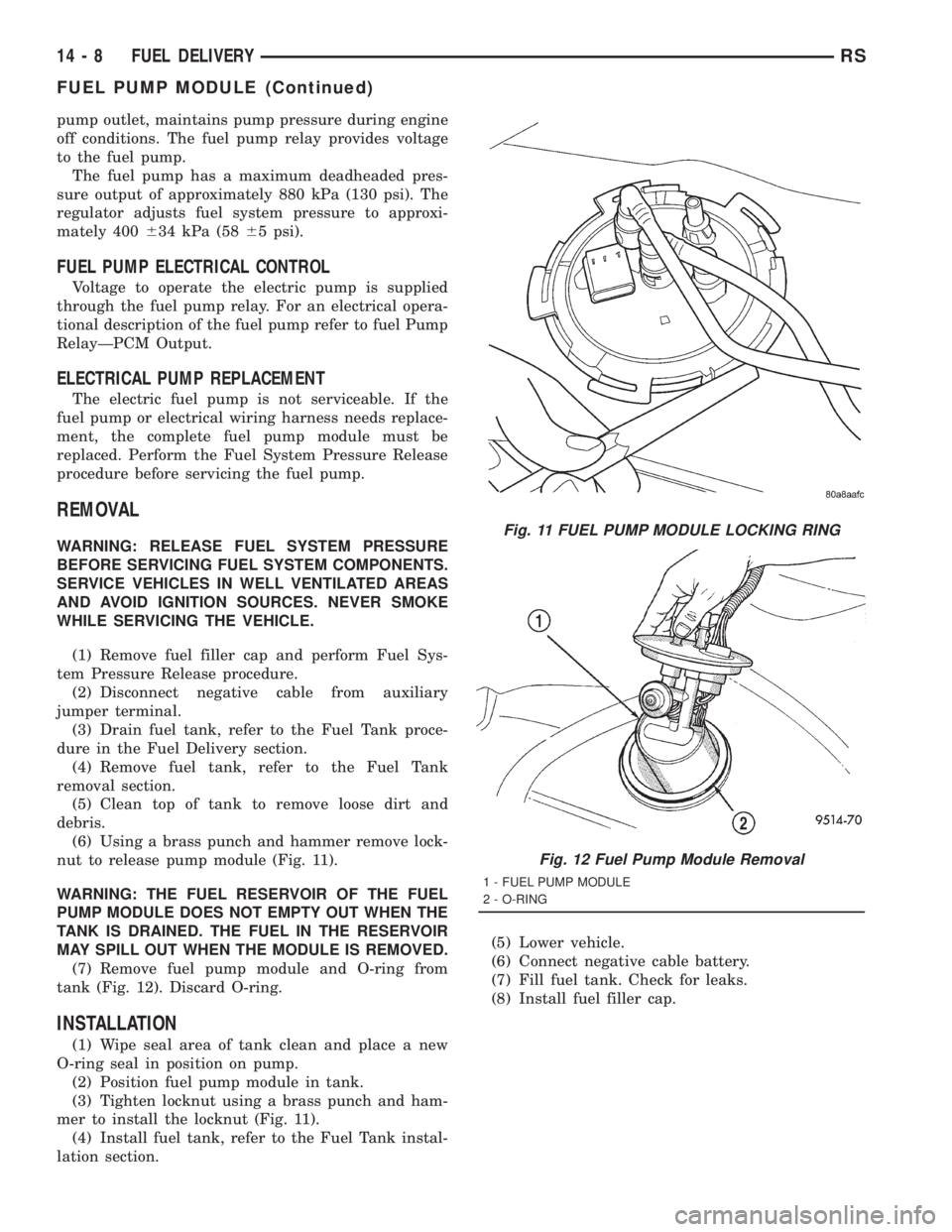
(6) Using a brass punch and hammer remove lock-
nut to release pump module (Fig. 11).
WARNING: THE FUEL RESERVOIR OF THE FUEL
PUMP MODULE DOES NOT EMPTY OUT WHEN THE
TANK IS DRAINED. THE FUEL IN THE RESERVOIR
MAY SPILL OUT WHEN THE MODULE IS REMOVED.
(7) Remove fuel pump module and O-ring from
tank (Fig. 12). Discard O-ring.
INSTALLATION
(1) Wipe seal area of tank clean and place a new
O-ring seal in position on pump.
(2) Position fuel pump module in tank.
(3) Tighten locknut using a brass punch and ham-
mer to install the locknut (Fig. 11).
(4) Install fuel tank, refer to the Fuel Tank instal-
lation section.(5) Lower vehicle.
(6) Connect negative cable battery.
(7) Fill fuel tank. Check for leaks.
(8) Install fuel filler cap.
Fig. 11 FUEL PUMP MODULE LOCKING RING
Fig. 12 Fuel Pump Module Removal
1 - FUEL PUMP MODULE
2 - O-RING
14 - 8 FUEL DELIVERYRS
FUEL PUMP MODULE (Continued)
Page 2886 of 4284
(5) Connect negative cable to battery or auxiliary
jumper terminal.
CAUTION: When using the ASD Fuel System Test,
the Auto Shutdown (ASD) Relay remains energized
for several minutes, until the test is stopped, or
until the ignition switch is turned to the Off posi-
tion.
(6) Use the DRB IIItscan tool ASD Fuel System
Test to pressurize the fuel system. Check for leaks.
TWO-TAB TYPE FITTING
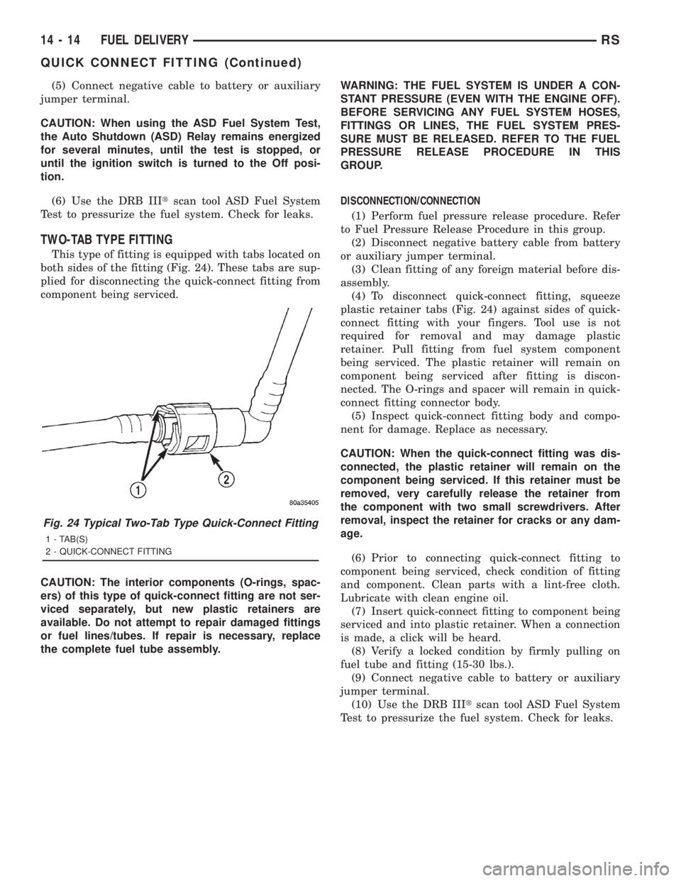
This type of fitting is equipped with tabs located on
both sides of the fitting (Fig. 24). These tabs are sup-
plied for disconnecting the quick-connect fitting from
component being serviced.
CAUTION: The interior components (O-rings, spac-
ers) of this type of quick-connect fitting are not ser-
viced separately, but new plastic retainers are
available. Do not attempt to repair damaged fittings
or fuel lines/tubes. If repair is necessary, replace
the complete fuel tube assembly.WARNING: THE FUEL SYSTEM IS UNDER A CON-
STANT PRESSURE (EVEN WITH THE ENGINE OFF).
BEFORE SERVICING ANY FUEL SYSTEM HOSES,
FITTINGS OR LINES, THE FUEL SYSTEM PRES-
SURE MUST BE RELEASED. REFER TO THE FUEL
PRESSURE RELEASE PROCEDURE IN THIS
GROUP.
DISCONNECTION/CONNECTION
(1) Perform fuel pressure release procedure. Refer
to Fuel Pressure Release Procedure in this group.
(2) Disconnect negative battery cable from battery
or auxiliary jumper terminal.
(3) Clean fitting of any foreign material before dis-
assembly.
(4) To disconnect quick-connect fitting, squeeze
plastic retainer tabs (Fig. 24) against sides of quick-
connect fitting with your fingers. Tool use is not
required for removal and may damage plastic
retainer. Pull fitting from fuel system component
being serviced. The plastic retainer will remain on
component being serviced after fitting is discon-
nected. The O-rings and spacer will remain in quick-
connect fitting connector body.
(5) Inspect quick-connect fitting body and compo-
nent for damage. Replace as necessary.
CAUTION: When the quick-connect fitting was dis-
connected, the plastic retainer will remain on the
component being serviced. If this retainer must be
removed, very carefully release the retainer from
the component with two small screwdrivers. After
removal, inspect the retainer for cracks or any dam-
age.
(6) Prior to connecting quick-connect fitting to
component being serviced, check condition of fitting
and component. Clean parts with a lint-free cloth.
Lubricate with clean engine oil.
(7) Insert quick-connect fitting to component being
serviced and into plastic retainer. When a connection
is made, a click will be heard.
(8) Verify a locked condition by firmly pulling on
fuel tube and fitting (15-30 lbs.).
(9) Connect negative cable to battery or auxiliary
jumper terminal.
(10) Use the DRB IIItscan tool ASD Fuel System
Test to pressurize the fuel system. Check for leaks.
Fig. 24 Typical Two-Tab Type Quick-Connect Fitting
1 - TAB(S)
2 - QUICK-CONNECT FITTING
14 - 14 FUEL DELIVERYRS
QUICK CONNECT FITTING (Continued)
Page 2888 of 4284
FUEL INJECTION
TABLE OF CONTENTS
page page
FUEL INJECTION
OPERATION.............................16
SPECIFICATIONS........................21
SPECIAL TOOLS.........................22
ACCELERATOR PEDAL
REMOVAL..............................23
INSTALLATION...........................23
CRANKSHAFT POSITION SENSOR
DESCRIPTION...........................23
OPERATION.............................23
REMOVAL..............................23
INSTALLATION...........................24
ENGINE SPEED SENSOR
DESCRIPTION...........................24
OPERATION.............................24
FUEL INJECTOR
DESCRIPTION...........................25
OPERATION.............................25
REMOVAL..............................25
INSTALLATION...........................26
FUEL PUMP RELAY
DESCRIPTION...........................27
OPERATION.............................27
IDLE AIR CONTROL MOTOR
DESCRIPTION...........................27
OPERATION.............................27
REMOVAL..............................28INSTALLATION...........................28
INLET AIR TEMPERATURE SENSOR
DESCRIPTION...........................28
OPERATION.............................28
MAP SENSOR
DESCRIPTION...........................29
OPERATION.............................29
REMOVAL..............................30
INSTALLATION...........................30
O2 SENSOR
DESCRIPTION...........................30
OPERATION.............................31
REMOVAL..............................32
INSTALLATION...........................33
THROTTLE BODY
DESCRIPTION...........................33
OPERATION.............................34
REMOVAL..............................34
INSTALLATION...........................34
THROTTLE CONTROL CABLE
REMOVAL..............................34
INSTALLATION...........................34
THROTTLE POSITION SENSOR
DESCRIPTION...........................34
OPERATION.............................35
REMOVAL..............................35
INSTALLATION...........................35
FUEL INJECTION
OPERATION - INJECTION SYSTEM
All engines used in this section have a sequential
Multi-Port Electronic Fuel Injection system. The MPI
system is computer regulated and provides precise
air/fuel ratios for all driving conditions. The Power-
train Control Module (PCM) operates the fuel injec-
tion system.
The PCM regulates:
²Ignition timing
²Air/fuel ratio
²Emission control devices
²Cooling fan
²Charging system
²Idle speed
²Vehicle speed control
Various sensors provide the inputs necessary for
the PCM to correctly operate these systems. In addi-tion to the sensors, various switches also provide
inputs to the PCM.
The PCM can adapt its programming to meet
changing operating conditions.
Fuel is injected into the intake port above the
intake valve in precise metered amounts through
electrically operated injectors. The PCM fires the
injectors in a specific sequence. Under most operat-
ing conditions, the PCM maintains an air fuel ratio
of 14.7 parts air to 1 part fuel by constantly adjust-
ing injector pulse width. Injector pulse width is the
length of time the injector is open.
The PCM adjusts injector pulse width by opening
and closing the ground path to the injector. Engine
RPM (speed) and manifold absolute pressure (air
density) are the primary inputs that determine injec-
tor pulse width.
OPERATION - MODES OF OPERATION
As input signals to the PCM change, the PCM
adjusts its response to output devices. For example,
14 - 16 FUEL INJECTIONRS
Page 2889 of 4284
the PCM must calculate a different injector pulse
width and ignition timing for idle than it does for
Wide Open Throttle (WOT). There are several differ-
ent modes of operation that determine how the PCM
responds to the various input signals.
There are two different areas of operation, OPEN
LOOP and CLOSED LOOP.
During OPEN LOOP modes the PCM receives
input signals and responds according to preset PCM
programming. Inputs from the upstream and down-
stream heated oxygen sensors are not monitored dur-
ing OPEN LOOP modes, except for heated oxygen
sensor diagnostics (they are checked for shorted con-
ditions at all times).
During CLOSED LOOP modes the PCM monitors
the inputs from the upstream and downstream
heated oxygen sensors. The upstream heated oxygen
sensor input tells the PCM if the calculated injector
pulse width resulted in the ideal air-fuel ratio of 14.7
to one. By monitoring the exhaust oxygen content
through the upstream heated oxygen sensor, the
PCM can fine tune injector pulse width. Fine tuning
injector pulse width allows the PCM to achieve opti-
mum fuel economy combined with low emissions.
For the PCM to enter CLOSED LOOP operation,
the following must occur:
(1) Engine coolant temperature must be over 35ÉF.
²If the coolant is over 35É the PCM will wait 44
seconds.
²If the coolant is over 50ÉF the PCM will wait 38
seconds.
²If the coolant is over 167ÉF the PCM will wait
11 seconds.
(2) For other temperatures the PCM will interpo-
late the correct waiting time.
(3) O2 sensor must read either greater than 0.745
volts or less than 0.1 volt.
(4) The multi-port fuel injection systems has the
following modes of operation:
²Ignition switch ON (Zero RPM)
²Engine start-up
²Engine warm-up
²Cruise
²Idle
²Acceleration
²Deceleration
²Wide Open Throttle
²Ignition switch OFF
(5) The engine start-up (crank), engine warm-up,
deceleration with fuel shutoff and wide open throttle
modes are OPEN LOOP modes. Under most operat-
ing conditions, the acceleration, deceleration (with
A/C on), idle and cruise modes,with the engine at
operating temperatureare CLOSED LOOP modes.IGNITION SWITCH ON (ZERO RPM) MODE
When the ignition switch activates the fuel injec-
tion system, the following actions occur:
²The PCM monitors the engine coolant tempera-
ture sensor and throttle position sensor input. The
PCM determines basic fuel injector pulse width from
this input.
²The PCM determines atmospheric air pressure
from the MAP sensor input to modify injector pulse
width.
When the key is in the ON position and the engine
is not running (zero rpm), the Auto Shutdown (ASD)
and fuel pump relays de-energize after approximately
1 second. Therefore, battery voltage is not supplied to
the fuel pump, ignition coil, fuel injectors and heated
oxygen sensors.
ENGINE START-UP MODE
This is an OPEN LOOP mode. If the vehicle is in
park or neutral (automatic transaxles) or the clutch
pedal is depressed (manual transaxles) the ignition
switch energizes the starter relay. The following
actions occur when the starter motor is engaged.
²If the PCM receives the camshaft position sensor
and crankshaft position sensor signals, it energizes
the Auto Shutdown (ASD) relay and fuel pump relay.
If the PCM does not receive both signals within
approximately one second, it will not energize the
ASD relay and fuel pump relay. The ASD and fuel
pump relays supply battery voltage to the fuel pump,
fuel injectors, ignition coil and heated oxygen sen-
sors.
²The PCM energizes the injectors (on the 69É
degree falling edge) for a calculated pulse width until
it determines crankshaft position from the camshaft
position sensor and crankshaft position sensor sig-
nals. The PCM determines crankshaft position within
1 engine revolution.
²After determining crankshaft position, the PCM
begins energizing the injectors in sequence. It adjusts
injector pulse width and controls injector synchroni-
zation by turning the individual ground paths to the
injectors On and Off.
²When the engine idles within664 RPM of its
target RPM, the PCM compares current MAP sensor
value with the atmospheric pressure value received
during the Ignition Switch On (zero RPM) mode.
Once the ASD and fuel pump relays have been
energized, the PCM determines injector pulse width
based on the following:
²Battery voltage
²Engine coolant temperature
²Engine RPM
²Inlet/Intake air temperature (IAT)
²MAP
²Throttle position
RSFUEL INJECTION14-17
FUEL INJECTION (Continued)
Page 2891 of 4284
momentarily turn off the injectors. This helps
improve fuel economy, emissions and engine braking.
WIDE-OPEN-THROTTLE MODE
This is an OPEN LOOP mode. During wide-open-
throttle operation, the following inputs are used by
the PCM:
²Inlet/Intake air temperature
²Engine coolant temperature
²Engine speed
²Knock sensor
²Manifold absolute pressure
²Throttle position
When the PCM senses a wide-open-throttle condi-
tion through the Throttle Position Sensor (TPS) it de-
energizes the A/C compressor clutch relay. This
disables the air conditioning system.
The PCM does not monitor the heated oxygen sen-
sor inputs during wide-open-throttle operation except
for downstream heated oxygen sensor and both
shorted diagnostics. The PCM adjusts injector pulse
width to supply a predetermined amount of addi-
tional fuel.
IGNITION SWITCH OFF MODE
When the operator turns the ignition switch to the
OFF position, the following occurs:
²All outputs are turned off, unless 02 Heater
Monitor test is being run. Refer to the Emission sec-
tion for On-Board Diagnostics.
²No inputs are monitored except for the heated
oxygen sensors. The PCM monitors the heating ele-
ments in the oxygen sensors and then shuts down.
FUEL CORRECTION or ADAPTIVE MEMORIES
DESCRIPTION
In Open Loop, the PCM changes pulse width with-
out feedback from the O2 Sensors. Once the engine
warms up to approximately 30 to 35É F, the PCM
goes into closed loopShort Term Correctionand
utilizes feedback from the O2 Sensors. Closed loop
Long Term Adaptive Memoryis maintained above
170É to 190É F unless the PCM senses wide open
throttle. At that time the PCM returns to Open Loop
operation.
OPERATION
Short Term
The first fuel correction program that begins func-
tioning is the short term fuel correction. This system
corrects fuel delivery in direct proportion to the read-
ings from the Upstream O2 Sensor.The PCM monitors the air/fuel ratio by using the
input voltage from the O2 Sensor. When the voltage
reaches its preset high or low limit, the PCM begins
to add or remove fuel until the sensor reaches its
switch point. The short term corrections then begin.
The PCM makes a series of quick changes in the
injector pulse-width until the O2 Sensor reaches its
opposite preset limit or switch point. The process
then repeats itself in the opposite direction.
Short term fuel correction will keep increasing or
decreasing injector pulse-width based upon the
upstream O2 Sensor input. The maximum range of
authority for short term memory is 25% (+/-) of base
pulse-width.
Long Term
The second fuel correction program is the long
term adaptive memory. In order to maintain correct
emission throughout all operating ranges of the
engine, a cell structure based on engine rpm and load
(MAP) is used.
Ther number of cells varies upon the driving con-
ditions. Two cells are used only during idle, based
upon TPS and Park/Neutral switch inputs. There
may be two other cells used for deceleration, based
on TPS, engine rpm, and vehicle speed. The other
twelve cells represent a manifold pressure and an
rpm range. Six of the cells are high rpm and the
other six are low rpm. Each of these cells is a specific
MAP voltage range .
As the engine enters one of these cells the PCM
looks at the amount of short term correction being
used. Because the goal is to keep short term at 0 (O2
Sensor switching at 0.5 volt), long term will update
in the same direction as short term correction was
moving to bring the short term back to 0. Once short
term is back at 0, this long term correction factor is
stored in memory.
The values stored in long term adaptive memory
are used for all operating conditions, including open
loop. However, the updating of the long term memory
occurs after the engine has exceeded approximately
17É F, with fuel control in closed loop and two min-
utes of engine run time. This is done to prevent any
transitional temperature or start-up compensations
from corrupting long term fuel correction.
Long term adaptive memory can change the pulse-
width by as much as 25%, which means it can correct
for all of short term. It is possible to have a problem
that would drive long term to 25% and short term to
another 25% for a total change of 50% away from
base pulse-width calculation.
RSFUEL INJECTION14-19
FUEL INJECTION (Continued)
Page 2897 of 4284
FUEL INJECTOR
DESCRIPTION
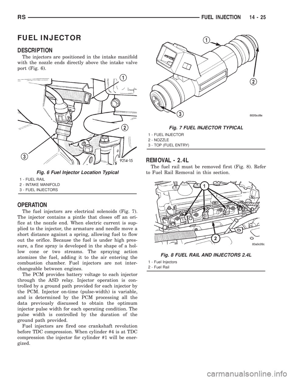
The injectors are positioned in the intake manifold
with the nozzle ends directly above the intake valve
port (Fig. 6).
OPERATION
The fuel injectors are electrical solenoids (Fig. 7).
The injector contains a pintle that closes off an ori-
fice at the nozzle end. When electric current is sup-
plied to the injector, the armature and needle move a
short distance against a spring, allowing fuel to flow
out the orifice. Because the fuel is under high pres-
sure, a fine spray is developed in the shape of a hol-
low cone or two streams. The spraying action
atomizes the fuel, adding it to the air entering the
combustion chamber. Fuel injectors are not inter-
changeable between engines.
The PCM provides battery voltage to each injector
through the ASD relay. Injector operation is con-
trolled by a ground path provided for each injector by
the PCM. Injector on-time (pulse-width) is variable,
and is determined by the PCM processing all the
data previously discussed to obtain the optimum
injector pulse width for each operating condition. The
pulse width is controlled by the duration of the
ground path provided.
Fuel injectors are fired one crankshaft revolution
before TDC compression. When cylinder #4 is at TDC
compression the injector for cylinder #1 will be ener-
gized.
REMOVAL - 2.4L
The fuel rail must be removed first (Fig. 8). Refer
to Fuel Rail Removal in this section.
Fig. 6 Fuel Injector Location Typical
1 - FUEL RAIL
2 - INTAKE MANIFOLD
3 - FUEL INJECTORS
Fig. 7 FUEL INJECTOR TYPICAL
1 - FUEL INJECTOR
2 - NOZZLE
3 - TOP (FUEL ENTRY)
Fig. 8 FUEL RAIL AND INJECTORS 2.4L
1 - Fuel Injectors
2 - Fuel Rail
RSFUEL INJECTION14-25