2001 CHRYSLER VOYAGER relay
[x] Cancel search: relayPage 2899 of 4284
FUEL PUMP RELAY
DESCRIPTION
The fuel pump relay is located in the PDC. The
inside top of the PDC cover has a label showing relay
and fuse location.
OPERATION
The fuel pump relay supplies battery voltage to the
fuel pump. A buss bar in the Power Distribution Cen-
ter (PDC) supplies voltage to the solenoid side and
contact side of the relay. The fuel pump relay power
circuit contains a fuse between the buss bar in the
PDC and the relay. The fuse also protects the power
circuit for the Automatic Shutdown (ASD) relay. The
fuse is located in the PDC. Refer to the Wiring Dia-
grams for circuit information.
The PCM controls the fuel pump relay by switch-
ing the ground path for the solenoid side of the relay
on and off. The PCM turns the ground path off when
the ignition switch is in the Off position. When the
ignition switch is in the On position, the PCM ener-
gizes the fuel pump. If the crankshaft position sensor
does not detect engine rotation, the PCM de-ener-
gizes the relay after approximately one second.
IDLE AIR CONTROL MOTOR
DESCRIPTION
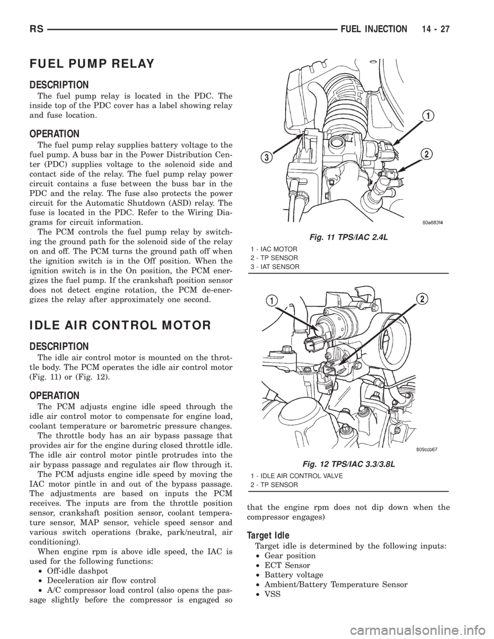
The idle air control motor is mounted on the throt-
tle body. The PCM operates the idle air control motor
(Fig. 11) or (Fig. 12).
OPERATION
The PCM adjusts engine idle speed through the
idle air control motor to compensate for engine load,
coolant temperature or barometric pressure changes.
The throttle body has an air bypass passage that
provides air for the engine during closed throttle idle.
The idle air control motor pintle protrudes into the
air bypass passage and regulates air flow through it.
The PCM adjusts engine idle speed by moving the
IAC motor pintle in and out of the bypass passage.
The adjustments are based on inputs the PCM
receives. The inputs are from the throttle position
sensor, crankshaft position sensor, coolant tempera-
ture sensor, MAP sensor, vehicle speed sensor and
various switch operations (brake, park/neutral, air
conditioning).
When engine rpm is above idle speed, the IAC is
used for the following functions:
²Off-idle dashpot
²Deceleration air flow control
²A/C compressor load control (also opens the pas-
sage slightly before the compressor is engaged sothat the engine rpm does not dip down when the
compressor engages)
Target Idle
Target idle is determined by the following inputs:
²Gear position
²ECT Sensor
²Battery voltage
²Ambient/Battery Temperature Sensor
²VSS
Fig. 11 TPS/IAC 2.4L
1 - IAC MOTOR
2 - TP SENSOR
3 - IAT SENSOR
Fig. 12 TPS/IAC 3.3/3.8L
1 - IDLE AIR CONTROL VALVE
2 - TP SENSOR
RSFUEL INJECTION14-27
Page 2903 of 4284
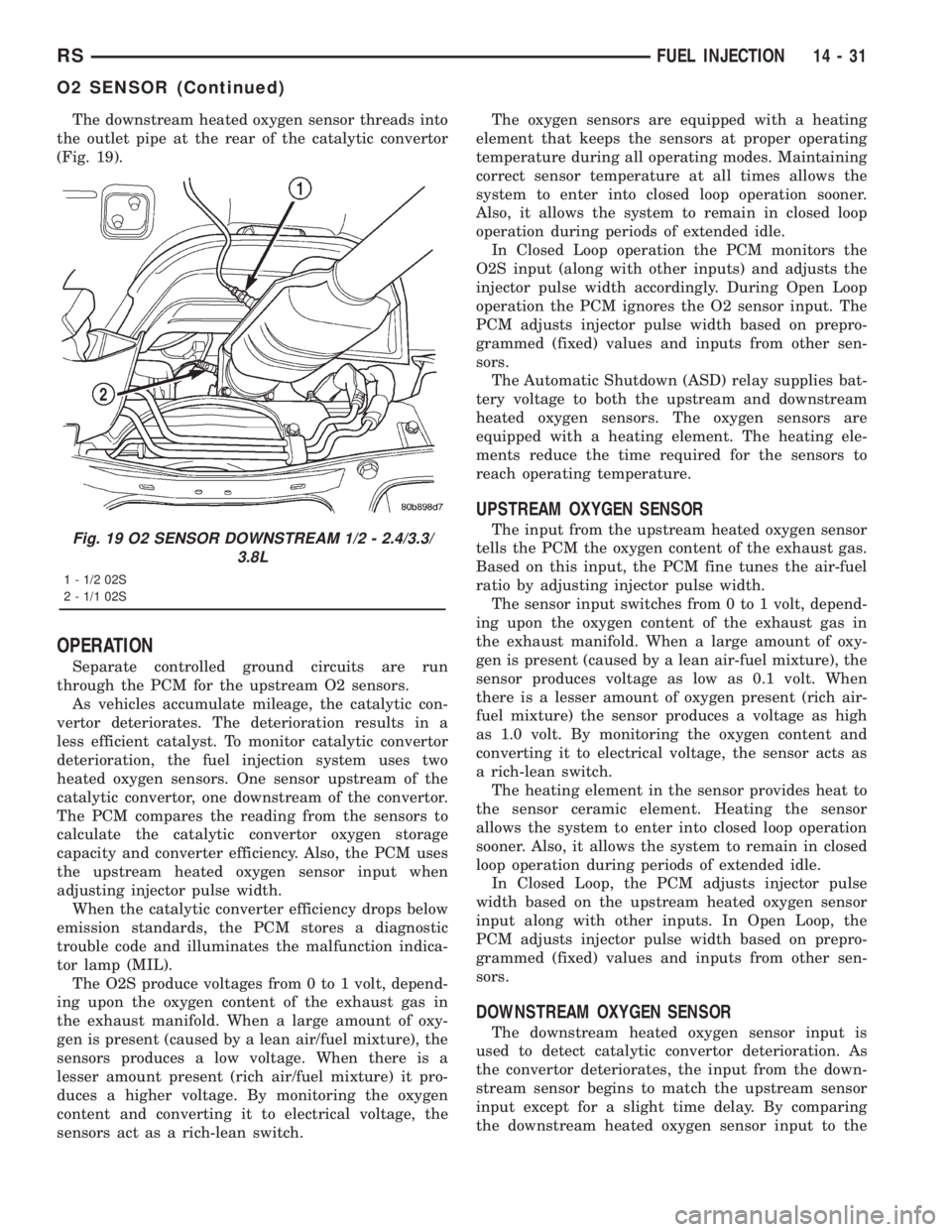
The downstream heated oxygen sensor threads into
the outlet pipe at the rear of the catalytic convertor
(Fig. 19).
OPERATION
Separate controlled ground circuits are run
through the PCM for the upstream O2 sensors.
As vehicles accumulate mileage, the catalytic con-
vertor deteriorates. The deterioration results in a
less efficient catalyst. To monitor catalytic convertor
deterioration, the fuel injection system uses two
heated oxygen sensors. One sensor upstream of the
catalytic convertor, one downstream of the convertor.
The PCM compares the reading from the sensors to
calculate the catalytic convertor oxygen storage
capacity and converter efficiency. Also, the PCM uses
the upstream heated oxygen sensor input when
adjusting injector pulse width.
When the catalytic converter efficiency drops below
emission standards, the PCM stores a diagnostic
trouble code and illuminates the malfunction indica-
tor lamp (MIL).
The O2S produce voltages from 0 to 1 volt, depend-
ing upon the oxygen content of the exhaust gas in
the exhaust manifold. When a large amount of oxy-
gen is present (caused by a lean air/fuel mixture), the
sensors produces a low voltage. When there is a
lesser amount present (rich air/fuel mixture) it pro-
duces a higher voltage. By monitoring the oxygen
content and converting it to electrical voltage, the
sensors act as a rich-lean switch.The oxygen sensors are equipped with a heating
element that keeps the sensors at proper operating
temperature during all operating modes. Maintaining
correct sensor temperature at all times allows the
system to enter into closed loop operation sooner.
Also, it allows the system to remain in closed loop
operation during periods of extended idle.
In Closed Loop operation the PCM monitors the
O2S input (along with other inputs) and adjusts the
injector pulse width accordingly. During Open Loop
operation the PCM ignores the O2 sensor input. The
PCM adjusts injector pulse width based on prepro-
grammed (fixed) values and inputs from other sen-
sors.
The Automatic Shutdown (ASD) relay supplies bat-
tery voltage to both the upstream and downstream
heated oxygen sensors. The oxygen sensors are
equipped with a heating element. The heating ele-
ments reduce the time required for the sensors to
reach operating temperature.
UPSTREAM OXYGEN SENSOR
The input from the upstream heated oxygen sensor
tells the PCM the oxygen content of the exhaust gas.
Based on this input, the PCM fine tunes the air-fuel
ratio by adjusting injector pulse width.
The sensor input switches from 0 to 1 volt, depend-
ing upon the oxygen content of the exhaust gas in
the exhaust manifold. When a large amount of oxy-
gen is present (caused by a lean air-fuel mixture), the
sensor produces voltage as low as 0.1 volt. When
there is a lesser amount of oxygen present (rich air-
fuel mixture) the sensor produces a voltage as high
as 1.0 volt. By monitoring the oxygen content and
converting it to electrical voltage, the sensor acts as
a rich-lean switch.
The heating element in the sensor provides heat to
the sensor ceramic element. Heating the sensor
allows the system to enter into closed loop operation
sooner. Also, it allows the system to remain in closed
loop operation during periods of extended idle.
In Closed Loop, the PCM adjusts injector pulse
width based on the upstream heated oxygen sensor
input along with other inputs. In Open Loop, the
PCM adjusts injector pulse width based on prepro-
grammed (fixed) values and inputs from other sen-
sors.
DOWNSTREAM OXYGEN SENSOR
The downstream heated oxygen sensor input is
used to detect catalytic convertor deterioration. As
the convertor deteriorates, the input from the down-
stream sensor begins to match the upstream sensor
input except for a slight time delay. By comparing
the downstream heated oxygen sensor input to the
Fig. 19 O2 SENSOR DOWNSTREAM 1/2 - 2.4/3.3/
3.8L
1 - 1/2 02S
2 - 1/1 02S
RSFUEL INJECTION14-31
O2 SENSOR (Continued)
Page 2909 of 4284
FUEL SYSTEM
TABLE OF CONTENTS
page page
FUEL SYSTEM 2.5L TURBO DIESEL
DESCRIPTION............................1
WARNING...............................1
DIAGNOSIS AND TESTING..................1
AIR IN FUEL SYSTEM....................1
FUEL SUPPLY RESTRICTIONS.............1STANDARD PROCEDURE...................2
WATER DRAINING AT FUEL FILTER.........2
CLEANING FUEL SYSTEM PARTS...........2
SPECIFICATIONS.........................2
FUEL DELIVERY..........................3
FUEL INJECTION........................10
FUEL SYSTEM 2.5L TURBO
DIESEL
DESCRIPTION - DIESEL FUEL DELIVERY
SYSTEM
The fuel system on the 2.5L Common Rail Diesel
Engine uses a fuel injection pump and an Electronic
Control Module (ECM).
The fuel delivery system consists of the:
²Accelerator pedal
²Air cleaner housing/element
²Fuel filter/water separator
²Fuel heater
²Fuel heater relay
²Fuel transfer (lift) pump
²Fuel injection pump
²Fuel injectors
²Fuel tank
²Fuel tank filler/vent tube assembly
²Fuel tank filler tube cap
²Fuel tank module containing the rollover valve
and a fuel gauge sending unit (fuel level sensor).
²Fuel tubes/lines/hoses
²High-pressure fuel injector lines
²Low-pressure fuel supply lines
²Low-pressure fuel return line
²Overflow valve
²Quick-connect fittings
²Water draining
WARNING - HIGH FUEL SYSTEM PRESSURE
WARNING: THE INJECTION PUMP SUPPLIES HIGH-
PRESSURE FUEL TO EACH INDIVIDUAL INJECTOR
THROUGH HIGH-PRESSURE LINES. FUEL UNDER
THIS AMOUNT OF PRESSURE CAN PENETRATE
SKIN AND CAUSE PERSONAL INJURY. WEAR
SAFETY GOGGLES AND ADEQUATE PROTECTIVE
CLOTHING. AVOID CONTACT WITH FUEL SPRAY
WHEN BLEEDING HIGH-PRESSURE FUEL LINES.
DIAGNOSIS AND TESTING - AIR IN FUEL
SYSTEM
Air will enter the fuel system whenever fuel supply
lines, separator filters, injection pump, high-pressure
lines or injectors are removed or disconnected. Air
trapped in the fuel system can result in hard start-
ing, a rough running engine, engine misfire, low
power, excessive smoke and fuel knock. After service
is performed, air must be bled from the system
before starting the engine.
Inspect the fuel system from the fuel transfer
pump to the injectors for loose connections. Leaking
fuel is an indicator of loose connections or defective
seals. Air can also enter the fuel system between the
fuel tank and the transfer pump. Inspect the fuel
tank and fuel lines for damage that might allow air
into the system.
DIAGNOSIS AND TESTING - FUEL SUPPLY
RESTRICTIONS
LOW-PRESSURE LINES
Fuel supply line restrictions or a defective fuel
transfer pump can cause starting problems and pre-
vent engine from accelerating. The starting problems
include; low power and/or white fog like exhaust.
Test all fuel supply lines for restrictions or block-
age. Flush or replace as necessary. Bleed fuel system
of air once a fuel supply line has been replaced. Refer
to Air Bleed Procedure for procedures.
To test for fuel line restrictions, a vacuum restric-
tion test may be performed. Refer to Fuel Transfer
Pump Pressure Test.
HIGH-PRESSURE LINES
Restricted (kinked or bent) high-pressure lines can
cause starting problems, poor engine performance,
engine mis-fire and white smoke from exhaust.
Examine all high-pressure lines for any damage.
Each radius on each high-pressure line must be
smooth and free of any bends or kinks.
RGFUEL SYSTEM14a-1
Page 2923 of 4284
OPERATION
The ECM uses the mass air flow (MAF) sensor to
measure air density. The MAF sensor contains a
ceramic element. A signal voltage is provided to the
element. As engine speed increases, airflow across
the ceramic element increases. Changes in air flow
and air density cause the temperature of the ceramic
element to fluxuate. The ceramic element changes
resistance respectively to changes in temperature.
The change in resistance varies the signal voltage
output to the ECM. The diesel power relay supplies
battery power the to MAF sensor. Ground is provided
by the ECM. The MAF sensor signal is provided by
the ECM.
REMOVAL
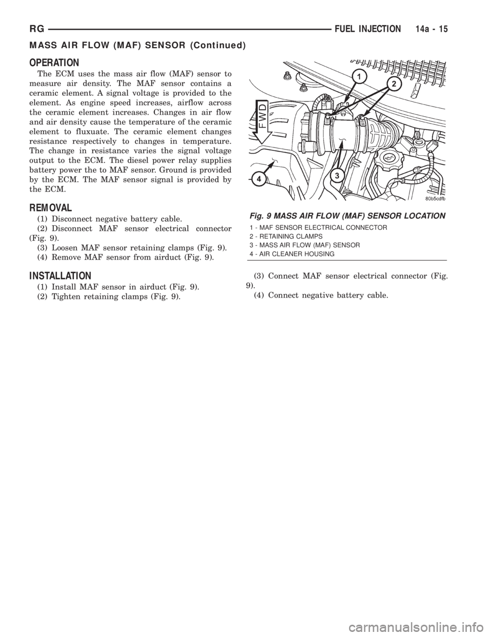
(1) Disconnect negative battery cable.
(2) Disconnect MAF sensor electrical connector
(Fig. 9).
(3) Loosen MAF sensor retaining clamps (Fig. 9).
(4) Remove MAF sensor from airduct (Fig. 9).
INSTALLATION
(1) Install MAF sensor in airduct (Fig. 9).
(2) Tighten retaining clamps (Fig. 9).(3) Connect MAF sensor electrical connector (Fig.
9).
(4) Connect negative battery cable.
Fig. 9 MASS AIR FLOW (MAF) SENSOR LOCATION
1 - MAF SENSOR ELECTRICAL CONNECTOR
2 - RETAINING CLAMPS
3 - MASS AIR FLOW (MAF) SENSOR
4 - AIR CLEANER HOUSING
RGFUEL INJECTION14a-15
MASS AIR FLOW (MAF) SENSOR (Continued)
Page 2994 of 4284
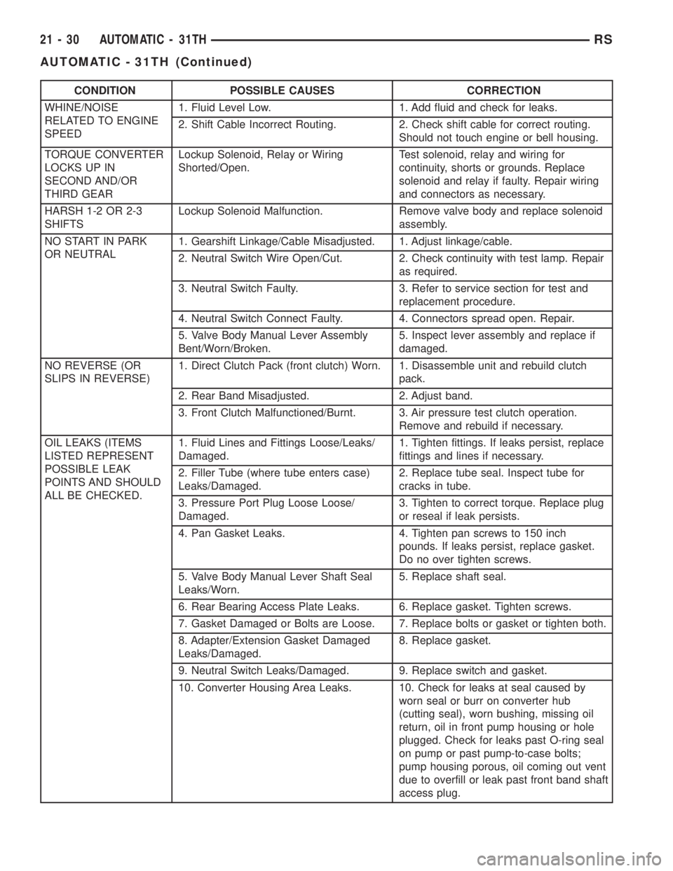
CONDITION POSSIBLE CAUSES CORRECTION
WHINE/NOISE
RELATED TO ENGINE
SPEED1. Fluid Level Low. 1. Add fluid and check for leaks.
2. Shift Cable Incorrect Routing. 2. Check shift cable for correct routing.
Should not touch engine or bell housing.
TORQUE CONVERTER
LOCKS UP IN
SECOND AND/OR
THIRD GEARLockup Solenoid, Relay or Wiring
Shorted/Open.Test solenoid, relay and wiring for
continuity, shorts or grounds. Replace
solenoid and relay if faulty. Repair wiring
and connectors as necessary.
HARSH 1-2 OR 2-3
SHIFTSLockup Solenoid Malfunction. Remove valve body and replace solenoid
assembly.
NO START IN PARK
OR NEUTRAL1. Gearshift Linkage/Cable Misadjusted. 1. Adjust linkage/cable.
2. Neutral Switch Wire Open/Cut. 2. Check continuity with test lamp. Repair
as required.
3. Neutral Switch Faulty. 3. Refer to service section for test and
replacement procedure.
4. Neutral Switch Connect Faulty. 4. Connectors spread open. Repair.
5. Valve Body Manual Lever Assembly
Bent/Worn/Broken.5. Inspect lever assembly and replace if
damaged.
NO REVERSE (OR
SLIPS IN REVERSE)1. Direct Clutch Pack (front clutch) Worn. 1. Disassemble unit and rebuild clutch
pack.
2. Rear Band Misadjusted. 2. Adjust band.
3. Front Clutch Malfunctioned/Burnt. 3. Air pressure test clutch operation.
Remove and rebuild if necessary.
OIL LEAKS (ITEMS
LISTED REPRESENT
POSSIBLE LEAK
POINTS AND SHOULD
ALL BE CHECKED.1. Fluid Lines and Fittings Loose/Leaks/
Damaged.1. Tighten fittings. If leaks persist, replace
fittings and lines if necessary.
2. Filler Tube (where tube enters case)
Leaks/Damaged.2. Replace tube seal. Inspect tube for
cracks in tube.
3. Pressure Port Plug Loose Loose/
Damaged.3. Tighten to correct torque. Replace plug
or reseal if leak persists.
4. Pan Gasket Leaks. 4. Tighten pan screws to 150 inch
pounds. If leaks persist, replace gasket.
Do no over tighten screws.
5. Valve Body Manual Lever Shaft Seal
Leaks/Worn.5. Replace shaft seal.
6. Rear Bearing Access Plate Leaks. 6. Replace gasket. Tighten screws.
7. Gasket Damaged or Bolts are Loose. 7. Replace bolts or gasket or tighten both.
8. Adapter/Extension Gasket Damaged
Leaks/Damaged.8. Replace gasket.
9. Neutral Switch Leaks/Damaged. 9. Replace switch and gasket.
10. Converter Housing Area Leaks. 10. Check for leaks at seal caused by
worn seal or burr on converter hub
(cutting seal), worn bushing, missing oil
return, oil in front pump housing or hole
plugged. Check for leaks past O-ring seal
on pump or past pump-to-case bolts;
pump housing porous, oil coming out vent
due to overfill or leak past front band shaft
access plug.
21 - 30 AUTOMATIC - 31THRS
AUTOMATIC - 31TH (Continued)
Page 3122 of 4284
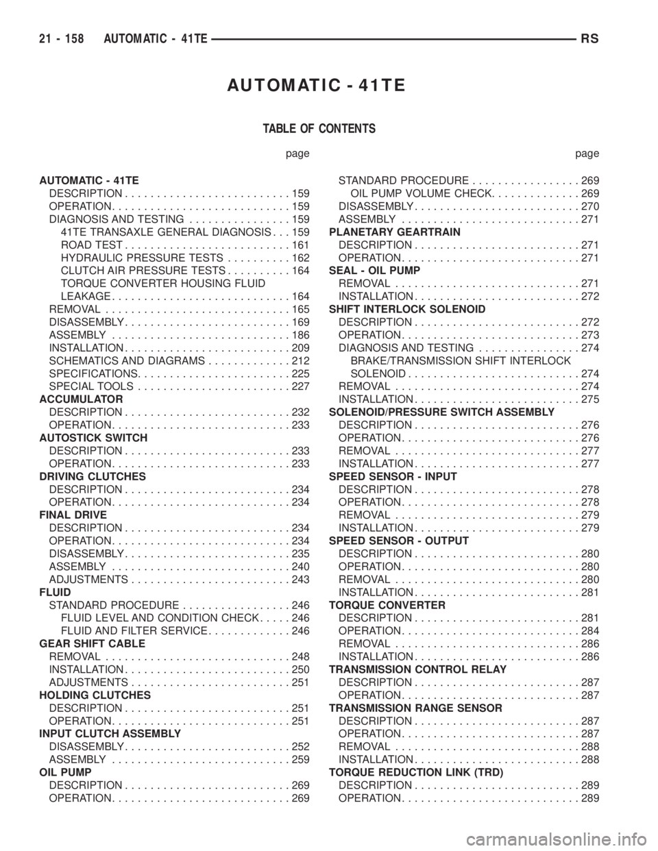
AUTOMATIC - 41TE
TABLE OF CONTENTS
page page
AUTOMATIC - 41TE
DESCRIPTION..........................159
OPERATION............................159
DIAGNOSIS AND TESTING................159
41TE TRANSAXLE GENERAL DIAGNOSIS . . . 159
ROAD TEST..........................161
HYDRAULIC PRESSURE TESTS..........162
CLUTCH AIR PRESSURE TESTS..........164
TORQUE CONVERTER HOUSING FLUID
LEAKAGE............................164
REMOVAL.............................165
DISASSEMBLY..........................169
ASSEMBLY............................186
INSTALLATION..........................209
SCHEMATICS AND DIAGRAMS.............212
SPECIFICATIONS........................225
SPECIAL TOOLS........................227
ACCUMULATOR
DESCRIPTION..........................232
OPERATION............................233
AUTOSTICK SWITCH
DESCRIPTION..........................233
OPERATION............................233
DRIVING CLUTCHES
DESCRIPTION..........................234
OPERATION............................234
FINAL DRIVE
DESCRIPTION..........................234
OPERATION............................234
DISASSEMBLY..........................235
ASSEMBLY............................240
ADJUSTMENTS.........................243
FLUID
STANDARD PROCEDURE.................246
FLUID LEVEL AND CONDITION CHECK.....246
FLUID AND FILTER SERVICE.............246
GEAR SHIFT CABLE
REMOVAL.............................248
INSTALLATION..........................250
ADJUSTMENTS.........................251
HOLDING CLUTCHES
DESCRIPTION..........................251
OPERATION............................251
INPUT CLUTCH ASSEMBLY
DISASSEMBLY..........................252
ASSEMBLY............................259
OIL PUMP
DESCRIPTION..........................269
OPERATION............................269STANDARD PROCEDURE.................269
OIL PUMP VOLUME CHECK..............269
DISASSEMBLY..........................270
ASSEMBLY............................271
PLANETARY GEARTRAIN
DESCRIPTION..........................271
OPERATION............................271
SEAL - OIL PUMP
REMOVAL.............................271
INSTALLATION..........................272
SHIFT INTERLOCK SOLENOID
DESCRIPTION..........................272
OPERATION............................273
DIAGNOSIS AND TESTING................274
BRAKE/TRANSMISSION SHIFT INTERLOCK
SOLENOID...........................274
REMOVAL.............................274
INSTALLATION..........................275
SOLENOID/PRESSURE SWITCH ASSEMBLY
DESCRIPTION..........................276
OPERATION............................276
REMOVAL.............................277
INSTALLATION..........................277
SPEED SENSOR - INPUT
DESCRIPTION..........................278
OPERATION............................278
REMOVAL.............................279
INSTALLATION..........................279
SPEED SENSOR - OUTPUT
DESCRIPTION..........................280
OPERATION............................280
REMOVAL.............................280
INSTALLATION..........................281
TORQUE CONVERTER
DESCRIPTION..........................281
OPERATION............................284
REMOVAL.............................286
INSTALLATION..........................286
TRANSMISSION CONTROL RELAY
DESCRIPTION..........................287
OPERATION............................287
TRANSMISSION RANGE SENSOR
DESCRIPTION..........................287
OPERATION............................287
REMOVAL.............................288
INSTALLATION..........................288
TORQUE REDUCTION LINK (TRD)
DESCRIPTION..........................289
OPERATION............................289
21 - 158 AUTOMATIC - 41TERS
Page 3123 of 4284
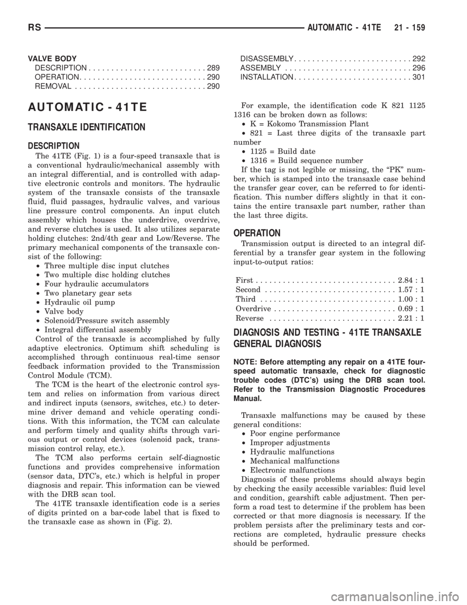
VALVE BODY
DESCRIPTION..........................289
OPERATION............................290
REMOVAL.............................290DISASSEMBLY..........................292
ASSEMBLY............................296
INSTALLATION..........................301
AUTOMATIC - 41TE
TRANSAXLE IDENTIFICATION
DESCRIPTION
The 41TE (Fig. 1) is a four-speed transaxle that is
a conventional hydraulic/mechanical assembly with
an integral differential, and is controlled with adap-
tive electronic controls and monitors. The hydraulic
system of the transaxle consists of the transaxle
fluid, fluid passages, hydraulic valves, and various
line pressure control components. An input clutch
assembly which houses the underdrive, overdrive,
and reverse clutches is used. It also utilizes separate
holding clutches: 2nd/4th gear and Low/Reverse. The
primary mechanical components of the transaxle con-
sist of the following:
²Three multiple disc input clutches
²Two multiple disc holding clutches
²Four hydraulic accumulators
²Two planetary gear sets
²Hydraulic oil pump
²Valve body
²Solenoid/Pressure switch assembly
²Integral differential assembly
Control of the transaxle is accomplished by fully
adaptive electronics. Optimum shift scheduling is
accomplished through continuous real-time sensor
feedback information provided to the Transmission
Control Module (TCM).
The TCM is the heart of the electronic control sys-
tem and relies on information from various direct
and indirect inputs (sensors, switches, etc.) to deter-
mine driver demand and vehicle operating condi-
tions. With this information, the TCM can calculate
and perform timely and quality shifts through vari-
ous output or control devices (solenoid pack, trans-
mission control relay, etc.).
The TCM also performs certain self-diagnostic
functions and provides comprehensive information
(sensor data, DTC's, etc.) which is helpful in proper
diagnosis and repair. This information can be viewed
with the DRB scan tool.
The 41TE transaxle identification code is a series
of digits printed on a bar-code label that is fixed to
the transaxle case as shown in (Fig. 2).For example, the identification code K 821 1125
1316 can be broken down as follows:
²K = Kokomo Transmission Plant
²821 = Last three digits of the transaxle part
number
²1125 = Build date
²1316 = Build sequence number
If the tag is not legible or missing, the ªPKº num-
ber, which is stamped into the transaxle case behind
the transfer gear cover, can be referred to for identi-
fication. This number differs slightly in that it con-
tains the entire transaxle part number, rather than
the last three digits.
OPERATION
Transmission output is directed to an integral dif-
ferential by a transfer gear system in the following
input-to-output ratios:
First...............................2.84 : 1
Second.............................1.57 : 1
Third..............................1.00 : 1
Overdrive...........................0.69 : 1
Reverse............................2.21 : 1
DIAGNOSIS AND TESTING - 41TE TRANSAXLE
GENERAL DIAGNOSIS
NOTE: Before attempting any repair on a 41TE four-
speed automatic transaxle, check for diagnostic
trouble codes (DTC's) using the DRB scan tool.
Refer to the Transmission Diagnostic Procedures
Manual.
Transaxle malfunctions may be caused by these
general conditions:
²Poor engine performance
²Improper adjustments
²Hydraulic malfunctions
²Mechanical malfunctions
²Electronic malfunctions
Diagnosis of these problems should always begin
by checking the easily accessible variables: fluid level
and condition, gearshift cable adjustment. Then per-
form a road test to determine if the problem has been
corrected or that more diagnosis is necessary. If the
problem persists after the preliminary tests and cor-
rections are completed, hydraulic pressure checks
should be performed.
RSAUTOMATIC - 41TE21 - 159
Page 3240 of 4284
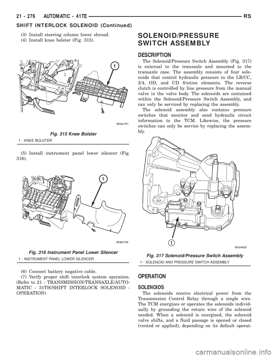
(3) Install steering column lower shroud.
(4) Install knee bolster (Fig. 315).
(5) Install instrument panel lower silencer (Fig.
316).
(6) Connect battery negative cable.
(7) Verify proper shift interlock system operation.
(Refer to 21 - TRANSMISSION/TRANSAXLE/AUTO-
MATIC - 31TH/SHIFT INTERLOCK SOLENOID -
OPERATION)SOLENOID/PRESSURE
SWITCH ASSEMBLY
DESCRIPTION
The Solenoid/Pressure Switch Assembly (Fig. 317)
is external to the transaxle and mounted to the
transaxle case. The assembly consists of four sole-
noids that control hydraulic pressure to the LR/CC,
2/4, OD, and UD friction elements. The reverse
clutch is controlled by line pressure from the manual
valve in the valve body. The solenoids are contained
within the Solenoid/Pressure Switch Assembly, and
can only be serviced by replacing the assembly.
The solenoid assembly also contains pressure
switches that monitor and send hydraulic circuit
information to the TCM. Likewise, the pressure
switches can only be service by replacing the assem-
bly.
OPERATION
SOLENOIDS
The solenoids receive electrical power from the
Transmission Control Relay through a single wire.
The TCM energizes or operates the solenoids individ-
ually by grounding the return wire of the solenoid
needed. When a solenoid is energized, the solenoid
valve shifts, and a fluid passage is opened or closed
(vented or applied), depending on its default operat-
Fig. 315 Knee Bolster
1 - KNEE BOLSTER
Fig. 316 Instrument Panel Lower Silencer
1 - INSTRUMENT PANEL LOWER SILENCERFig. 317 Solenoid/Pressure Switch Assembly
1 - SOLENOID AND PRESSURE SWITCH ASSEMBLY
21 - 276 AUTOMATIC - 41TERS
SHIFT INTERLOCK SOLENOID (Continued)