2001 CHRYSLER VOYAGER relay
[x] Cancel search: relayPage 3675 of 4284
BLOWER MOTOR
DESCRIPTION
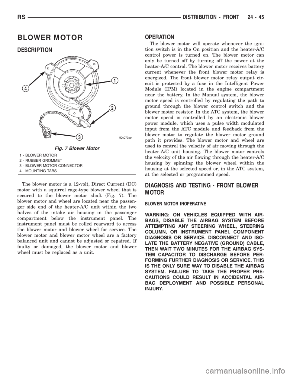
The blower motor is a 12-volt, Direct Current (DC)
motor with a squirrel cage-type blower wheel that is
secured to the blower motor shaft (Fig. 7). The
blower motor and wheel are located near the passen-
ger side end of the heater-A/C unit within the two
halves of the intake air housing in the passenger
compartment below the instrument panel. The
instrument panel must be rolled rearward to access
the blower motor and blower wheel for service. The
blower motor and blower motor wheel are a factory
balanced unit and cannot be adjusted or repaired. If
faulty or damaged, the blower motor and blower
wheel must be replaced as a unit.
OPERATION
The blower motor will operate whenever the igni-
tion switch is in the On position and the heater-A/C
control power is turned on. The blower motor can
only be turned off by turning off the power at the
heater-A/C control. The blower motor receives battery
current whenever the front blower motor relay is
energized. The front blower motor relay output cir-
cuit is protected by a fuse in the Intelligent Power
Module (IPM) located in the engine compartment
near the battery. In the Manual system, the blower
motor speed is controlled by regulating the path to
ground through the blower control switch and the
blower motor resistor. In the ATC system, the blower
motor speed is controlled by an electronic blower
power module, which uses a pulse width modulated
input from the ATC module and feedback from the
blower motor to regulate the blower motor ground
path it provides. The blower motor and wheel are
used to control the velocity of air moving through the
heater-A/C unit housing. The blower motor controls
the velocity of the air flowing through the heater-A/C
housing by spinning the blower wheel within the
housing at the selected speed or, in the ATC system,
at the selected or programmed speed.
DIAGNOSIS AND TESTING - FRONT BLOWER
MOTOR
BLOWER MOTOR INOPERATIVE
WARNING: ON VEHICLES EQUIPPED WITH AIR-
BAGS, DISABLE THE AIRBAG SYSTEM BEFORE
ATTEMPTING ANY STEERING WHEEL, STEERING
COLUMN, OR INSTRUMENT PANEL COMPONENT
DIAGNOSIS OR SERVICE. DISCONNECT AND ISO-
LATE THE BATTERY NEGATIVE (GROUND) CABLE,
THEN WAIT TWO MINUTES FOR THE AIRBAG SYS-
TEM CAPACITOR TO DISCHARGE BEFORE PER-
FORMING FURTHER DIAGNOSIS OR SERVICE. THIS
IS THE ONLY SURE WAY TO DISABLE THE AIRBAG
SYSTEM. FAILURE TO TAKE THE PROPER PRE-
CAUTIONS COULD RESULT IN ACCIDENTAL AIR-
BAG DEPLOYMENT AND POSSIBLE PERSONAL
INJURY.
Fig. 7 Blower Motor
1 - BLOWER MOTOR
2 - RUBBER GROMMET
3 - BLOWER MOTOR CONNECTOR
4 - MOUNTING TABS
RSDISTRIBUTION - FRONT24-45
Page 3676 of 4284
(1) Check the fuse (Fuse 10 - 40 ampere) in the
Intelligent Power Module (IPM). If OK, go to Step 2.
If not OK, repair the shorted circuit or component as
required and replace the faulty fuse.
(2) Turn the ignition switch to the On position. Be
certain that the heater-A/C control power is turned
on. Check for battery voltage at the fuse (Fuse 10 -
40 ampere) in the IPM. If OK, go to Step 3. If not
OK, proceed to diagnosis of the front blower motor
relay. (Refer to 24 - HEATING & AIR CONDITION-
ING/CONTROLS - FRONT/BLOWER MOTOR
RELAY - DIAGNOSIS AND TESTING).
(3) Turn the ignition switch to the Off position.
Disconnect and isolate the battery negative cable.
Disconnect the front HVAC wire harness connector
for the front blower motor resistor (Manual Temper-
ature Control) or the front blower power module
(Automatic Temperature Control) from the resistor or
module connector receptacle. Reconnect the battery
negative cable. Turn the ignition switch to the On
position. Be certain that the heater-A/C control
power is turned on. Check for battery voltage at the
fused front blower motor relay output circuit cavity
of the front HVAC wire harness connector for thefront blower motor resistor (MTC) or the front blower
power module (ATC). If OK, go to Step 4. If not OK,
repair the open fused front blower motor relay output
circuit to the IPM as required.
(4) Turn the ignition switch to the Off position.
Disconnect and isolate the battery negative cable.
Disconnect the front blower motor pigtail wire con-
nector from the connector receptacle of the front
blower motor resistor (MTC) or the front blower
power module (ATC). Use jumper wires to connect a
battery and ground feeds to the blower motor pigtail
wire connector. The blower motor should operate. If
OK with MTC, proceed to diagnosis of the front
blower motor resistor. (Refer to 24 - HEATING & AIR
CONDITIONING/CONTROLS - FRONT/BLOWER
MOTOR RESISTOR - DIAGNOSIS AND TESTING).
If OK with ATC, use a DRBIII scan tool to diagnose
the front blower power module. Refer to the appropri-
ate diagnostic information. If not OK with MTC or
ATC, replace the faulty front blower motor.
BLOWER MOTOR NOISE OR VIBRATION
Refer to the Blower Motor Noise/Vibration Diagno-
sis chart (Fig. 8).
24 - 46 DISTRIBUTION - FRONTRS
BLOWER MOTOR (Continued)
Page 3686 of 4284
system control switch on the front heater-A/C control
is not in the Off position. The blower motor can only
be turned off by turning off the rear system at the
front heater-A/C control. The blower motor receives
battery current whenever the rear blower motor
relay is energized. The rear blower motor relay out-
put circuit is protected by a fuse in the Intelligent
Power Module (IPM) located in the engine compart-
ment near the battery. In the MTC system, the
blower motor speed is controlled by regulating the
path to ground through the blower control switch and
the blower motor resistor. In the ATC system, the
blower motor speed is controlled by an electronic
blower power module, which uses a pulse width mod-
ulated input from the ATC module and feedback from
the blower motor to regulate the blower motor
ground path it provides. The blower motor and wheel
are used to control the velocity of air moving through
the rear heater-A/C unit housing. The blower motor
controls the velocity of the air flowing through the
rear heater-A/C housing by spinning the blower
wheel within the housing at the selected speed or, in
the ATC system, at the selected or programmed
speed.
DIAGNOSIS AND TESTING - REAR BLOWER
MOTOR
BLOWER MOTOR INOPERATIVE
(1) Check the fuse (Fuse 12 - 25 ampere) in the
Intelligent Power Module (IPM). If OK, go to Step 2.
If not OK, repair the shorted circuit or component as
required and replace the faulty fuse.
(2) Turn the ignition switch to the On position. Be
certain that the rear heater-A/C control power is
turned on. Check for battery voltage at the fuse
(Fuse 12 - 25 ampere) in the IPM. If OK, go to Step
3. If not OK, proceed to diagnosis of the rear blower
motor relay. (Refer to 24 - HEATING & AIR CONDI-TIONING/CONTROLS - REAR/BLOWER MOTOR
RELAY - DIAGNOSIS AND TESTING).
(3) Turn the ignition switch to the Off position.
Disconnect and isolate the battery negative cable.
Disconnect the rear HVAC wire harness connector for
the rear blower motor resistor (Manual Temperature
Control) or the rear blower power module (Automatic
Temperature Control) from the resistor or module
connector receptacle. Reconnect the battery negative
cable. Turn the ignition switch to the On position. Be
certain that the rear heater-A/C control power is
turned on. Check for battery voltage at the fused
rear blower motor relay output circuit cavity of the
rear HVAC wire harness connector for the rear
blower motor resistor (MTC) or the rear blower
power module (ATC). If OK, go to Step 4. If not OK,
repair the open fused front blower motor relay output
circuit to the IPM as required.
(4) Turn the ignition switch to the Off position.
Disconnect and isolate the battery negative cable.
Disconnect the rear blower motor pigtail wire connec-
tor from the take out and connector of the rear
HVAC wire harness (MTC) or the connector recepta-
cle of the rear blower power module (ATC). Use
jumper wires to connect a battery and ground feeds
to the blower motor pigtail wire connector. The
blower motor should operate. If OK with MTC, pro-
ceed to diagnosis of the rear blower motor resistor.
(Refer to 24 - HEATING & AIR CONDITIONING/
CONTROLS - REAR/BLOWER MOTOR RESISTOR -
DIAGNOSIS AND TESTING). If OK with ATC, use a
DRBIII scan tool to diagnose the rear blower power
module. Refer to the appropriate diagnostic informa-
tion. If not OK with MTC or ATC, replace the faulty
rear blower motor.
BLOWER MOTOR NOISE OR VIBRATION
Refer to the Blower Motor Noise/Vibration Diagno-
sis chart (Fig. 4).
24 - 56 DISTRIBUTION - REARRS
BLOWER MOTOR (Continued)
Page 3753 of 4284
²Vehicle Speed Sensor
²Engine Coolant Temperature Sensor
²Throttle Position Sensor
²Engine Controller Self Test Faults
²Cam or Crank Sensor
²Injector and Coil
²Idle Air Control Motor
²EVAP Electrical
²EGR Solenoid Electrical
²Intake Air Temperature
²5 Volt Feed
ConflictÐThe Task Manager does not run the
Oxygen Sensor Monitor if any of the following condi-
tions are present:
²A/C ON (A/C clutch cycling temporarily sus-
pends monitor)
²Purge flow in progress
²Ethanel content learn is takeng place and the
ethenal used once flag is set
SuspendÐThe Task Manager suspends maturing
a fault for the Oxygen Sensor Monitor if an of the fol-
lowing are present:
²Oxygen Sensor Heater Monitor, Priority 1
²Misfire Monitor, Priority 2
OXYGEN SENSOR HEATER MONITOR
DESCRIPTIONÐIf there is an oxygen sensor
(O2S) DTC as well as a O2S heater DTC, the O2S
fault MUST be repaired first. After the O2S fault is
repaired, verify that the heater circuit is operating
correctly.
The voltage readings taken from the O2S are very
temperature sensitive. The readings are not accurate
below 300ÉC. Heating of the O2S is done to allow the
engine controller to shift to closed loop control as
soon as possible. The heating element used to heat
the O2S must be tested to ensure that it is heating
the sensor properly.
The heater element itself is not tested. The sensor
output is used to test the heater by isolating the
effect of the heater element on the O2S output volt-
age from the other effects. The resistance is normally
between 100 ohms and 4.5 megaohms. When oxygen
sensor temperature increases, the resistance in the
internal circuit decreases. The PCM sends a 5 volts
biased signal through the oxygen sensors to ground
this monitoring circuit. As the temperature increases,
resistance decreases and the PCM detects a lower
voltage at the reference signal. Inversely, as the tem-
perature decreases, the resistance increases and the
PCM detects a higher voltage at the reference signal.
The O2S circuit is monitored for a drop in voltage.
OPERATIONÐThe Oxygen Sensor Heater Moni-
tor begins after the ignition has been turned OFF
and the O2 sensors have cooled. The PCM sends a 5
volt bias to the oxygen sensor every 1.6 seconds. ThePCM keeps it biased for 35 ms each time. As the sen-
sor cools down, the resistance increases and the PCM
reads the increase in voltage. Once voltage has
increased to a predetermined amount, higher than
when the test started, the oxygen sensor is cool
enough to test heater operation.
When the oxygen sensor is cool enough, the PCM
energizes the ASD relay. Voltage to the O2 sensor
begins to increase the temperature. As the sensor
temperature increases, the internal resistance
decreases. The PCM continues biasing the 5 volt sig-
nal to the sensor. Each time the signal is biased, the
PCM reads a voltage decrease. When the PCM
detects a voltage decrease of a predetermined value
for several biased pulses, the test passes.
The heater elements are tested each time the
engine is turned OFF if all the enabling conditions
are met. If the monitor fails, the PCM stores a
maturing fault and a Freeze Frame is entered. If two
consecutive tests fail, a DTC is stored. Because the
ignition is OFF, the MIL is illuminated at the begin-
ning of the next key cycle.
Enabling ConditionsÐThe following conditions
must be met for the PCM to run the oxygen sensor
heater test:
²Engine run time of at least 5.1 minutes
²Key OFF power down
²Battery voltage of at least 10 volts
²Sufficient Oxygen Sensor cool down
Pending ConditionsÐThere are not conditions or
situations that prompt conflict or suspension of test-
ing. The oxygen sensor heater test is not run pending
resolution of MIL illumination due to oxygen sensor
failure.
SuspendÐThere are no conditions which exist for
suspending the Heater Monitor.
CATALYST MONITOR
To comply with clean air regulations, vehicles are
equipped with catalytic converters. These converters
reduce the emission of hydrocarbons, oxides of nitro-
gen and carbon monoxide.
Normal vehicle miles or engine misfire can cause a
catalyst to decay. A meltdown of the ceramic core can
cause a reduction of the exhaust passage. This can
increase vehicle emissions and deteriorate engine
performance, driveability and fuel economy.
The catalyst monitor uses dual oxygen sensors
(O2S's) to monitor the efficiency of the converter. The
dual O2S strategy is based on the fact that as a cat-
alyst deteriorates, its oxygen storage capacity and its
efficiency are both reduced. By monitoring the oxy-
gen storage capacity of a catalyst, its efficiency can
be indirectly calculated. The upstream O2S is used to
detect the amount of oxygen in the exhaust gas
before the gas enters the catalytic converter. The
RSEMISSIONS CONTROL25-3
EMISSIONS CONTROL (Continued)
Page 3784 of 4284
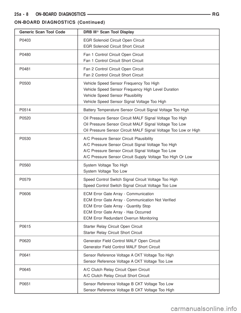
Generic Scan Tool Code DRB IIITScan Tool Display
P0403 EGR Solenoid Circuit Open Circuit
EGR Solenoid Circuit Short Circuit
P0480 Fan 1 Control Circuit Open Circuit
Fan 1 Control Circuit Short Circuit
P0481 Fan 2 Control Circuit Open Circuit
Fan 2 Control Circuit Short Circuit
P0500 Vehicle Speed Sensor Frequency Too High
Vehicle Speed Sensor Frequency High Level Duration
Vehicle Speed Sensor Plausibility
Vehicle Speed Sensor Signal Voltage Too High
P0514 Battery Temperature Sensor Circuit Signal Voltage Too High
P0520 Oil Pressure Sensor Circuit MALF Signal Voltage Too High
Oil Pressure Sensor Circuit MALF Signal Voltage Too Low
Oil Pressure Sensor Circuit MALF Signal Voltage Too Low or High
P0530 A/C Pressure Sensor Circuit Plausibility
A/C Pressure Sensor Circuit Signal Voltage Too High
A/C Pressure Sensor Circuit Signal Voltage Too Low
A/C Pressure Sensor Circuit Supply Voltage Too High Or Low
P0560 System Voltage Too High
System Voltage Too Low
P0579 Speed Control Switch Signal Circuit Voltage Too High
Speed Control Switch Signal Circuit Voltage Too Low
P0606 ECM Error Gate Array - Communication
ECM Error Gate Array - Communication Not Verified
ECM Error Gate Array - Quantity Stop
ECM Error Gate Array - Has Occurred
ECM Error Redundant Overrun Monitoring
P0615 Starter Relay Circuit Open Circuit
Starter Relay Circuit Short Circuit
P0620 Generator Field Control MALF Open Circuit
Generator Field Control MALF Short Circuit
P0641 Sensor Reference Voltage A CKT Voltage Too High
Sensor Reference Voltage A CKT Voltage Too Low
P0645 A/C Clutch Relay Circuit Open Circuit
A/C Clutch Relay Circuit Short Circuit
P0651 Sensor Reference Voltage B CKT Voltage Too Low
Sensor Reference Voltage B CKT Voltage Too High
25a - 8 ON-BOARD DIAGNOSTICSRG
ON-BOARD DIAGNOSTICS (Continued)
Page 3785 of 4284
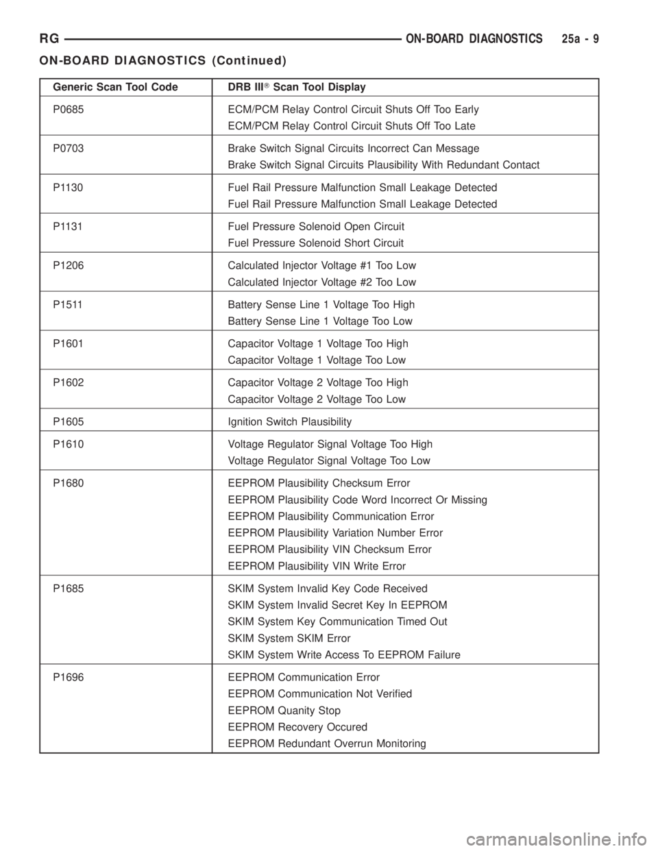
Generic Scan Tool Code DRB IIITScan Tool Display
P0685 ECM/PCM Relay Control Circuit Shuts Off Too Early
ECM/PCM Relay Control Circuit Shuts Off Too Late
P0703 Brake Switch Signal Circuits Incorrect Can Message
Brake Switch Signal Circuits Plausibility With Redundant Contact
P1130 Fuel Rail Pressure Malfunction Small Leakage Detected
Fuel Rail Pressure Malfunction Small Leakage Detected
P1131 Fuel Pressure Solenoid Open Circuit
Fuel Pressure Solenoid Short Circuit
P1206 Calculated Injector Voltage #1 Too Low
Calculated Injector Voltage #2 Too Low
P1511 Battery Sense Line 1 Voltage Too High
Battery Sense Line 1 Voltage Too Low
P1601 Capacitor Voltage 1 Voltage Too High
Capacitor Voltage 1 Voltage Too Low
P1602 Capacitor Voltage 2 Voltage Too High
Capacitor Voltage 2 Voltage Too Low
P1605 Ignition Switch Plausibility
P1610 Voltage Regulator Signal Voltage Too High
Voltage Regulator Signal Voltage Too Low
P1680 EEPROM Plausibility Checksum Error
EEPROM Plausibility Code Word Incorrect Or Missing
EEPROM Plausibility Communication Error
EEPROM Plausibility Variation Number Error
EEPROM Plausibility VIN Checksum Error
EEPROM Plausibility VIN Write Error
P1685 SKIM System Invalid Key Code Received
SKIM System Invalid Secret Key In EEPROM
SKIM System Key Communication Timed Out
SKIM System SKIM Error
SKIM System Write Access To EEPROM Failure
P1696 EEPROM Communication Error
EEPROM Communication Not Verified
EEPROM Quanity Stop
EEPROM Recovery Occured
EEPROM Redundant Overrun Monitoring
RGON-BOARD DIAGNOSTICS25a-9
ON-BOARD DIAGNOSTICS (Continued)
Page 3791 of 4284
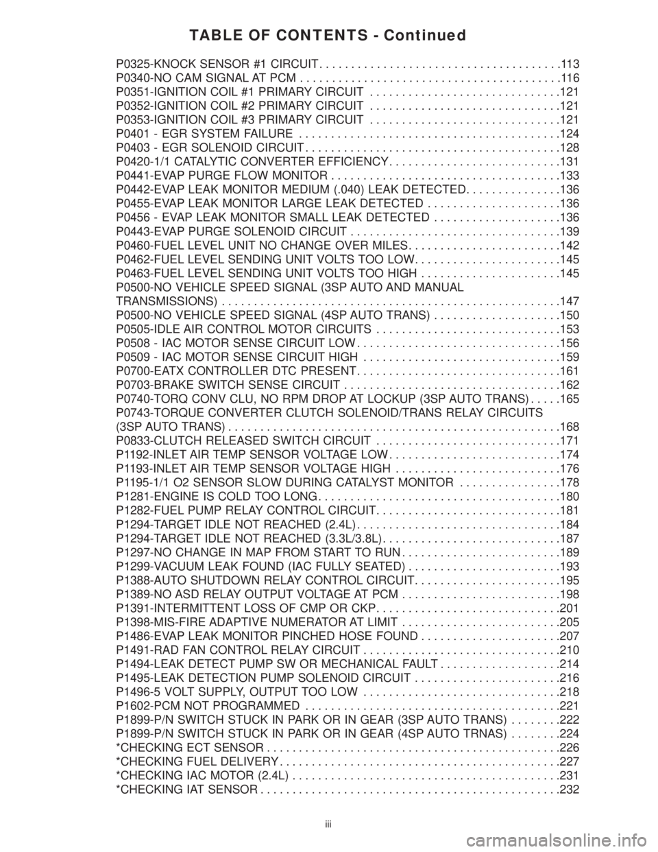
TABLE OF CONTENTS - Continued
P0325-KNOCK SENSOR #1 CIRCUIT......................................113
P0340-NO CAM SIGNAL AT PCM.........................................116
P0351-IGNITION COIL #1 PRIMARY CIRCUIT..............................121
P0352-IGNITION COIL #2 PRIMARY CIRCUIT..............................121
P0353-IGNITION COIL #3 PRIMARY CIRCUIT..............................121
P0401 - EGR SYSTEM FAILURE.........................................124
P0403 - EGR SOLENOID CIRCUIT........................................128
P0420-1/1 CATALYTIC CONVERTER EFFICIENCY...........................131
P0441-EVAP PURGE FLOW MONITOR....................................133
P0442-EVAP LEAK MONITOR MEDIUM (.040) LEAK DETECTED...............136
P0455-EVAP LEAK MONITOR LARGE LEAK DETECTED.....................136
P0456 - EVAP LEAK MONITOR SMALL LEAK DETECTED....................136
P0443-EVAP PURGE SOLENOID CIRCUIT.................................139
P0460-FUEL LEVEL UNIT NO CHANGE OVER MILES........................142
P0462-FUEL LEVEL SENDING UNIT VOLTS TOO LOW.......................145
P0463-FUEL LEVEL SENDING UNIT VOLTS TOO HIGH......................145
P0500-NO VEHICLE SPEED SIGNAL (3SP AUTO AND MANUAL
TRANSMISSIONS).....................................................147
P0500-NO VEHICLE SPEED SIGNAL (4SP AUTO TRANS)....................150
P0505-IDLE AIR CONTROL MOTOR CIRCUITS.............................153
P0508 - IAC MOTOR SENSE CIRCUIT LOW................................156
P0509 - IAC MOTOR SENSE CIRCUIT HIGH...............................159
P0700-EATX CONTROLLER DTC PRESENT................................161
P0703-BRAKE SWITCH SENSE CIRCUIT..................................162
P0740-TORQ CONV CLU, NO RPM DROP AT LOCKUP (3SP AUTO TRANS).....165
P0743-TORQUE CONVERTER CLUTCH SOLENOID/TRANS RELAY CIRCUITS
(3SP AUTO TRANS)....................................................168
P0833-CLUTCH RELEASED SWITCH CIRCUIT.............................171
P1192-INLET AIR TEMP SENSOR VOLTAGE LOW...........................174
P1193-INLET AIR TEMP SENSOR VOLTAGE HIGH..........................176
P1195-1/1 O2 SENSOR SLOW DURING CATALYST MONITOR................178
P1281-ENGINE IS COLD TOO LONG......................................180
P1282-FUEL PUMP RELAY CONTROL CIRCUIT.............................181
P1294-TARGET IDLE NOT REACHED (2.4L)................................184
P1294-TARGET IDLE NOT REACHED (3.3L/3.8L)............................187
P1297-NO CHANGE IN MAP FROM START TO RUN.........................189
P1299-VACUUM LEAK FOUND (IAC FULLY SEATED)........................193
P1388-AUTO SHUTDOWN RELAY CONTROL CIRCUIT.......................195
P1389-NO ASD RELAY OUTPUT VOLTAGE AT PCM.........................198
P1391-INTERMITTENT LOSS OF CMP OR CKP.............................201
P1398-MIS-FIRE ADAPTIVE NUMERATOR AT LIMIT.........................205
P1486-EVAP LEAK MONITOR PINCHED HOSE FOUND......................207
P1491-RAD FAN CONTROL RELAY CIRCUIT...............................210
P1494-LEAK DETECT PUMP SW OR MECHANICAL FAULT...................214
P1495-LEAK DETECTION PUMP SOLENOID CIRCUIT.......................216
P1496-5 VOLT SUPPLY, OUTPUT TOO LOW...............................218
P1602-PCM NOT PROGRAMMED........................................221
P1899-P/N SWITCH STUCK IN PARK OR IN GEAR (3SP AUTO TRANS)........222
P1899-P/N SWITCH STUCK IN PARK OR IN GEAR (4SP AUTO TRNAS)........224
*CHECKING ECT SENSOR..............................................226
*CHECKING FUEL DELIVERY............................................227
*CHECKING IAC MOTOR (2.4L)..........................................231
*CHECKING IAT SENSOR...............................................232
iii
Page 3792 of 4284
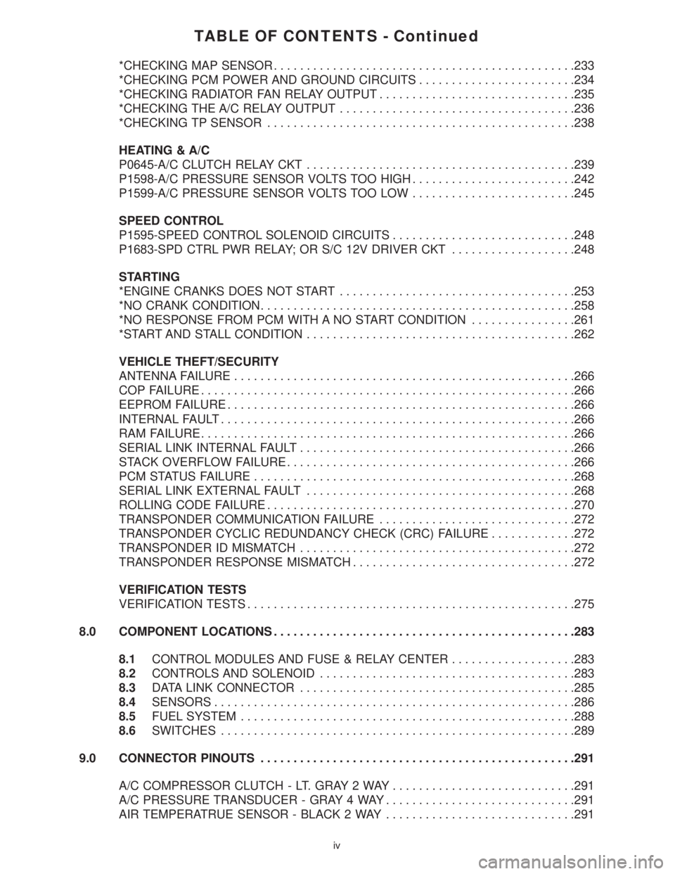
TABLE OF CONTENTS - Continued
*CHECKING MAP SENSOR..............................................233
*CHECKING PCM POWER AND GROUND CIRCUITS........................234
*CHECKING RADIATOR FAN RELAY OUTPUT..............................235
*CHECKING THE A/C RELAY OUTPUT....................................236
*CHECKING TP SENSOR...............................................238
HEATING & A/C
P0645-A/C CLUTCH RELAY CKT.........................................239
P1598-A/C PRESSURE SENSOR VOLTS TOO HIGH.........................242
P1599-A/C PRESSURE SENSOR VOLTS TOO LOW.........................245
SPEED CONTROL
P1595-SPEED CONTROL SOLENOID CIRCUITS............................248
P1683-SPD CTRL PWR RELAY; OR S/C 12V DRIVER CKT...................248
STARTING
*ENGINE CRANKS DOES NOT START....................................253
*NO CRANK CONDITION................................................258
*NO RESPONSE FROM PCM WITH A NO START CONDITION................261
*START AND STALL CONDITION.........................................262
VEHICLE THEFT/SECURITY
ANTENNA FAILURE....................................................266
COP FAILURE.........................................................266
EEPROM FAILURE.....................................................266
INTERNAL FAULT......................................................266
RAM FAILURE.........................................................266
SERIAL LINK INTERNAL FAULT..........................................266
STACK OVERFLOW FAILURE............................................266
PCM STATUS FAILURE.................................................268
SERIAL LINK EXTERNAL FAULT.........................................268
ROLLING CODE FAILURE...............................................270
TRANSPONDER COMMUNICATION FAILURE..............................272
TRANSPONDER CYCLIC REDUNDANCY CHECK (CRC) FAILURE.............272
TRANSPONDER ID MISMATCH..........................................272
TRANSPONDER RESPONSE MISMATCH..................................272
VERIFICATION TESTS
VERIFICATION TESTS..................................................275
8.0 COMPONENT LOCATIONS..............................................283
8.1CONTROL MODULES AND FUSE & RELAY CENTER...................283
8.2CONTROLS AND SOLENOID.......................................283
8.3DATA LINK CONNECTOR..........................................285
8.4SENSORS.......................................................286
8.5FUEL SYSTEM...................................................288
8.6SWITCHES......................................................289
9.0 CONNECTOR PINOUTS................................................291
A/C COMPRESSOR CLUTCH - LT. GRAY 2 WAY............................291
A/C PRESSURE TRANSDUCER - GRAY 4 WAY.............................291
AIR TEMPERATRUE SENSOR - BLACK 2 WAY.............................291
iv