2001 CHRYSLER VOYAGER display
[x] Cancel search: displayPage 1267 of 4284
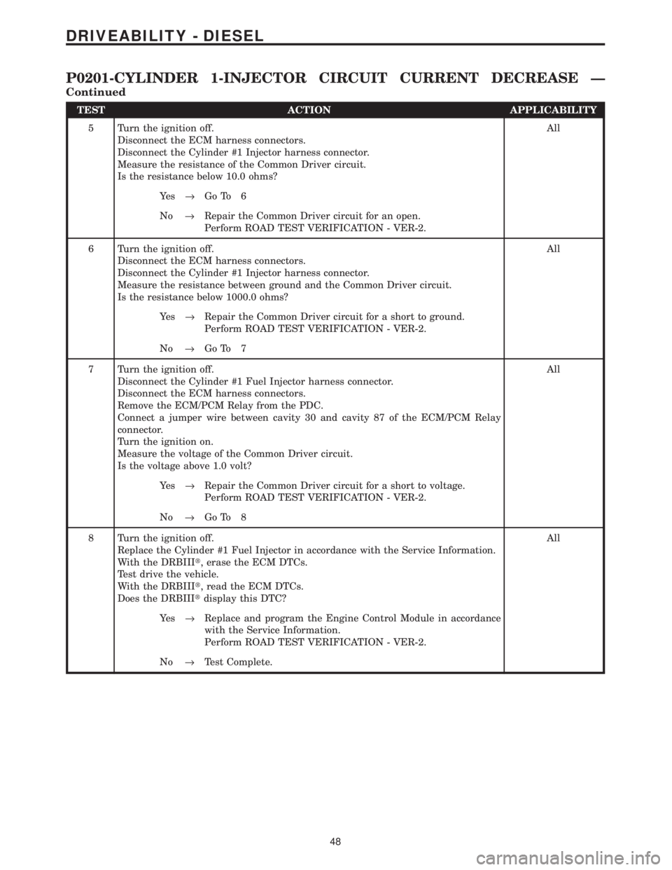
TEST ACTION APPLICABILITY
5 Turn the ignition off.
Disconnect the ECM harness connectors.
Disconnect the Cylinder #1 Injector harness connector.
Measure the resistance of the Common Driver circuit.
Is the resistance below 10.0 ohms?All
Ye s®Go To 6
No®Repair the Common Driver circuit for an open.
Perform ROAD TEST VERIFICATION - VER-2.
6 Turn the ignition off.
Disconnect the ECM harness connectors.
Disconnect the Cylinder #1 Injector harness connector.
Measure the resistance between ground and the Common Driver circuit.
Is the resistance below 1000.0 ohms?All
Ye s®Repair the Common Driver circuit for a short to ground.
Perform ROAD TEST VERIFICATION - VER-2.
No®Go To 7
7 Turn the ignition off.
Disconnect the Cylinder #1 Fuel Injector harness connector.
Disconnect the ECM harness connectors.
Remove the ECM/PCM Relay from the PDC.
Connect a jumper wire between cavity 30 and cavity 87 of the ECM/PCM Relay
connector.
Turn the ignition on.
Measure the voltage of the Common Driver circuit.
Is the voltage above 1.0 volt?All
Ye s®Repair the Common Driver circuit for a short to voltage.
Perform ROAD TEST VERIFICATION - VER-2.
No®Go To 8
8 Turn the ignition off.
Replace the Cylinder #1 Fuel Injector in accordance with the Service Information.
With the DRBIIIt, erase the ECM DTCs.
Test drive the vehicle.
With the DRBIIIt, read the ECM DTCs.
Does the DRBIIItdisplay this DTC?All
Ye s®Replace and program the Engine Control Module in accordance
with the Service Information.
Perform ROAD TEST VERIFICATION - VER-2.
No®Test Complete.
48
DRIVEABILITY - DIESEL
P0201-CYLINDER 1-INJECTOR CIRCUIT CURRENT DECREASE Ð
Continued
Page 1270 of 4284
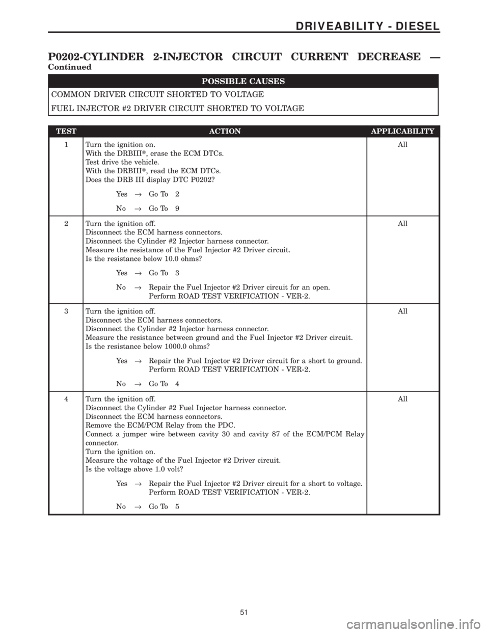
POSSIBLE CAUSES
COMMON DRIVER CIRCUIT SHORTED TO VOLTAGE
FUEL INJECTOR #2 DRIVER CIRCUIT SHORTED TO VOLTAGE
TEST ACTION APPLICABILITY
1 Turn the ignition on.
With the DRBIIIt, erase the ECM DTCs.
Test drive the vehicle.
With the DRBIIIt, read the ECM DTCs.
Does the DRB III display DTC P0202?All
Ye s®Go To 2
No®Go To 9
2 Turn the ignition off.
Disconnect the ECM harness connectors.
Disconnect the Cylinder #2 Injector harness connector.
Measure the resistance of the Fuel Injector #2 Driver circuit.
Is the resistance below 10.0 ohms?All
Ye s®Go To 3
No®Repair the Fuel Injector #2 Driver circuit for an open.
Perform ROAD TEST VERIFICATION - VER-2.
3 Turn the ignition off.
Disconnect the ECM harness connectors.
Disconnect the Cylinder #2 Injector harness connector.
Measure the resistance between ground and the Fuel Injector #2 Driver circuit.
Is the resistance below 1000.0 ohms?All
Ye s®Repair the Fuel Injector #2 Driver circuit for a short to ground.
Perform ROAD TEST VERIFICATION - VER-2.
No®Go To 4
4 Turn the ignition off.
Disconnect the Cylinder #2 Fuel Injector harness connector.
Disconnect the ECM harness connectors.
Remove the ECM/PCM Relay from the PDC.
Connect a jumper wire between cavity 30 and cavity 87 of the ECM/PCM Relay
connector.
Turn the ignition on.
Measure the voltage of the Fuel Injector #2 Driver circuit.
Is the voltage above 1.0 volt?All
Ye s®Repair the Fuel Injector #2 Driver circuit for a short to voltage.
Perform ROAD TEST VERIFICATION - VER-2.
No®Go To 5
51
DRIVEABILITY - DIESEL
P0202-CYLINDER 2-INJECTOR CIRCUIT CURRENT DECREASE Ð
Continued
Page 1271 of 4284
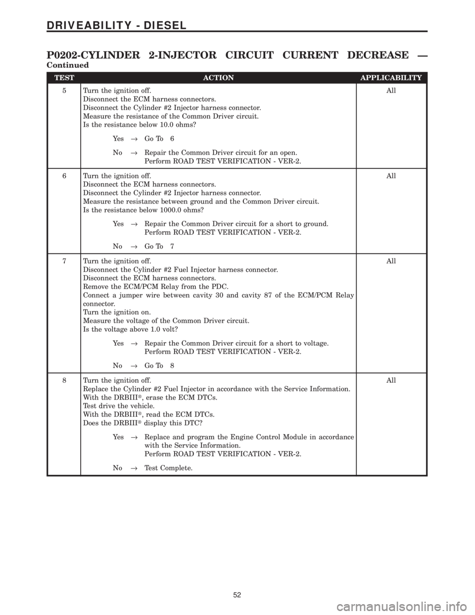
TEST ACTION APPLICABILITY
5 Turn the ignition off.
Disconnect the ECM harness connectors.
Disconnect the Cylinder #2 Injector harness connector.
Measure the resistance of the Common Driver circuit.
Is the resistance below 10.0 ohms?All
Ye s®Go To 6
No®Repair the Common Driver circuit for an open.
Perform ROAD TEST VERIFICATION - VER-2.
6 Turn the ignition off.
Disconnect the ECM harness connectors.
Disconnect the Cylinder #2 Injector harness connector.
Measure the resistance between ground and the Common Driver circuit.
Is the resistance below 1000.0 ohms?All
Ye s®Repair the Common Driver circuit for a short to ground.
Perform ROAD TEST VERIFICATION - VER-2.
No®Go To 7
7 Turn the ignition off.
Disconnect the Cylinder #2 Fuel Injector harness connector.
Disconnect the ECM harness connectors.
Remove the ECM/PCM Relay from the PDC.
Connect a jumper wire between cavity 30 and cavity 87 of the ECM/PCM Relay
connector.
Turn the ignition on.
Measure the voltage of the Common Driver circuit.
Is the voltage above 1.0 volt?All
Ye s®Repair the Common Driver circuit for a short to voltage.
Perform ROAD TEST VERIFICATION - VER-2.
No®Go To 8
8 Turn the ignition off.
Replace the Cylinder #2 Fuel Injector in accordance with the Service Information.
With the DRBIIIt, erase the ECM DTCs.
Test drive the vehicle.
With the DRBIIIt, read the ECM DTCs.
Does the DRBIIItdisplay this DTC?All
Ye s®Replace and program the Engine Control Module in accordance
with the Service Information.
Perform ROAD TEST VERIFICATION - VER-2.
No®Test Complete.
52
DRIVEABILITY - DIESEL
P0202-CYLINDER 2-INJECTOR CIRCUIT CURRENT DECREASE Ð
Continued
Page 1274 of 4284
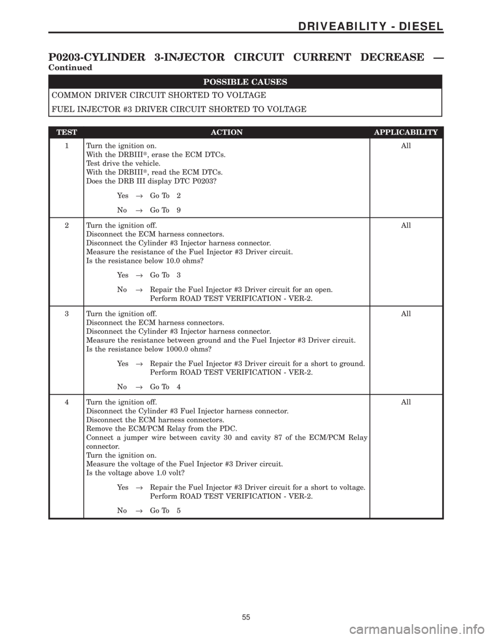
POSSIBLE CAUSES
COMMON DRIVER CIRCUIT SHORTED TO VOLTAGE
FUEL INJECTOR #3 DRIVER CIRCUIT SHORTED TO VOLTAGE
TEST ACTION APPLICABILITY
1 Turn the ignition on.
With the DRBIIIt, erase the ECM DTCs.
Test drive the vehicle.
With the DRBIIIt, read the ECM DTCs.
Does the DRB III display DTC P0203?All
Ye s®Go To 2
No®Go To 9
2 Turn the ignition off.
Disconnect the ECM harness connectors.
Disconnect the Cylinder #3 Injector harness connector.
Measure the resistance of the Fuel Injector #3 Driver circuit.
Is the resistance below 10.0 ohms?All
Ye s®Go To 3
No®Repair the Fuel Injector #3 Driver circuit for an open.
Perform ROAD TEST VERIFICATION - VER-2.
3 Turn the ignition off.
Disconnect the ECM harness connectors.
Disconnect the Cylinder #3 Injector harness connector.
Measure the resistance between ground and the Fuel Injector #3 Driver circuit.
Is the resistance below 1000.0 ohms?All
Ye s®Repair the Fuel Injector #3 Driver circuit for a short to ground.
Perform ROAD TEST VERIFICATION - VER-2.
No®Go To 4
4 Turn the ignition off.
Disconnect the Cylinder #3 Fuel Injector harness connector.
Disconnect the ECM harness connectors.
Remove the ECM/PCM Relay from the PDC.
Connect a jumper wire between cavity 30 and cavity 87 of the ECM/PCM Relay
connector.
Turn the ignition on.
Measure the voltage of the Fuel Injector #3 Driver circuit.
Is the voltage above 1.0 volt?All
Ye s®Repair the Fuel Injector #3 Driver circuit for a short to voltage.
Perform ROAD TEST VERIFICATION - VER-2.
No®Go To 5
55
DRIVEABILITY - DIESEL
P0203-CYLINDER 3-INJECTOR CIRCUIT CURRENT DECREASE Ð
Continued
Page 1275 of 4284
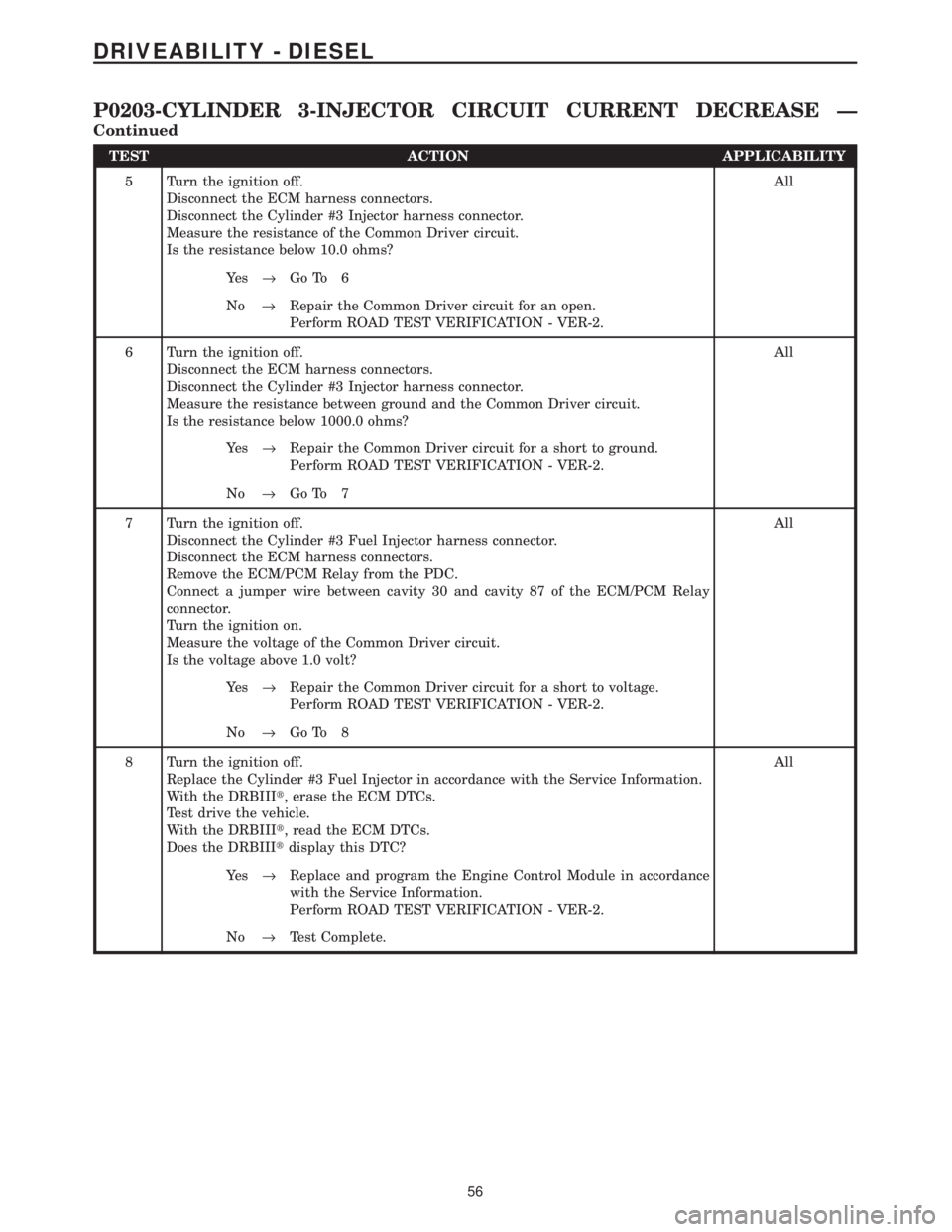
TEST ACTION APPLICABILITY
5 Turn the ignition off.
Disconnect the ECM harness connectors.
Disconnect the Cylinder #3 Injector harness connector.
Measure the resistance of the Common Driver circuit.
Is the resistance below 10.0 ohms?All
Ye s®Go To 6
No®Repair the Common Driver circuit for an open.
Perform ROAD TEST VERIFICATION - VER-2.
6 Turn the ignition off.
Disconnect the ECM harness connectors.
Disconnect the Cylinder #3 Injector harness connector.
Measure the resistance between ground and the Common Driver circuit.
Is the resistance below 1000.0 ohms?All
Ye s®Repair the Common Driver circuit for a short to ground.
Perform ROAD TEST VERIFICATION - VER-2.
No®Go To 7
7 Turn the ignition off.
Disconnect the Cylinder #3 Fuel Injector harness connector.
Disconnect the ECM harness connectors.
Remove the ECM/PCM Relay from the PDC.
Connect a jumper wire between cavity 30 and cavity 87 of the ECM/PCM Relay
connector.
Turn the ignition on.
Measure the voltage of the Common Driver circuit.
Is the voltage above 1.0 volt?All
Ye s®Repair the Common Driver circuit for a short to voltage.
Perform ROAD TEST VERIFICATION - VER-2.
No®Go To 8
8 Turn the ignition off.
Replace the Cylinder #3 Fuel Injector in accordance with the Service Information.
With the DRBIIIt, erase the ECM DTCs.
Test drive the vehicle.
With the DRBIIIt, read the ECM DTCs.
Does the DRBIIItdisplay this DTC?All
Ye s®Replace and program the Engine Control Module in accordance
with the Service Information.
Perform ROAD TEST VERIFICATION - VER-2.
No®Test Complete.
56
DRIVEABILITY - DIESEL
P0203-CYLINDER 3-INJECTOR CIRCUIT CURRENT DECREASE Ð
Continued
Page 1278 of 4284
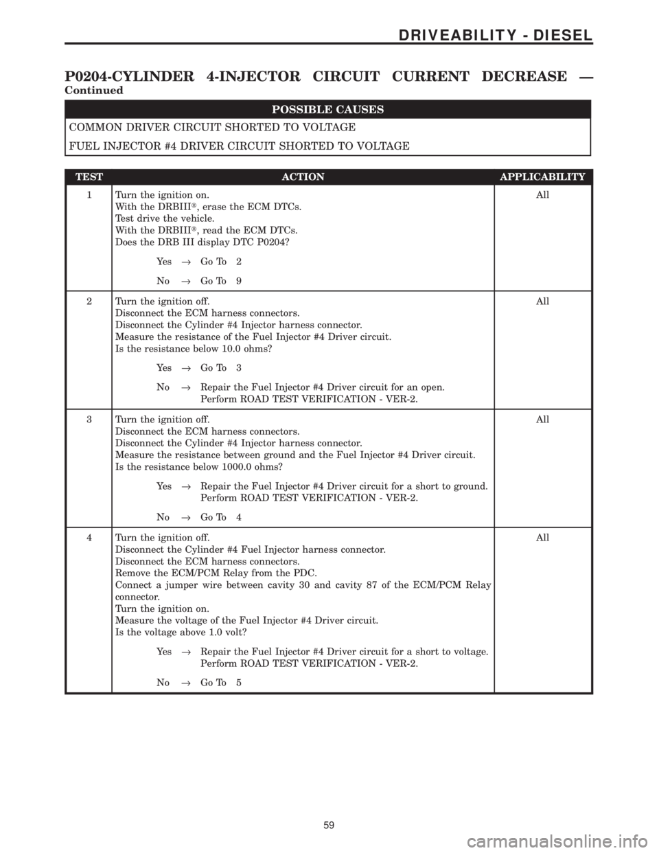
POSSIBLE CAUSES
COMMON DRIVER CIRCUIT SHORTED TO VOLTAGE
FUEL INJECTOR #4 DRIVER CIRCUIT SHORTED TO VOLTAGE
TEST ACTION APPLICABILITY
1 Turn the ignition on.
With the DRBIIIt, erase the ECM DTCs.
Test drive the vehicle.
With the DRBIIIt, read the ECM DTCs.
Does the DRB III display DTC P0204?All
Ye s®Go To 2
No®Go To 9
2 Turn the ignition off.
Disconnect the ECM harness connectors.
Disconnect the Cylinder #4 Injector harness connector.
Measure the resistance of the Fuel Injector #4 Driver circuit.
Is the resistance below 10.0 ohms?All
Ye s®Go To 3
No®Repair the Fuel Injector #4 Driver circuit for an open.
Perform ROAD TEST VERIFICATION - VER-2.
3 Turn the ignition off.
Disconnect the ECM harness connectors.
Disconnect the Cylinder #4 Injector harness connector.
Measure the resistance between ground and the Fuel Injector #4 Driver circuit.
Is the resistance below 1000.0 ohms?All
Ye s®Repair the Fuel Injector #4 Driver circuit for a short to ground.
Perform ROAD TEST VERIFICATION - VER-2.
No®Go To 4
4 Turn the ignition off.
Disconnect the Cylinder #4 Fuel Injector harness connector.
Disconnect the ECM harness connectors.
Remove the ECM/PCM Relay from the PDC.
Connect a jumper wire between cavity 30 and cavity 87 of the ECM/PCM Relay
connector.
Turn the ignition on.
Measure the voltage of the Fuel Injector #4 Driver circuit.
Is the voltage above 1.0 volt?All
Ye s®Repair the Fuel Injector #4 Driver circuit for a short to voltage.
Perform ROAD TEST VERIFICATION - VER-2.
No®Go To 5
59
DRIVEABILITY - DIESEL
P0204-CYLINDER 4-INJECTOR CIRCUIT CURRENT DECREASE Ð
Continued
Page 1279 of 4284
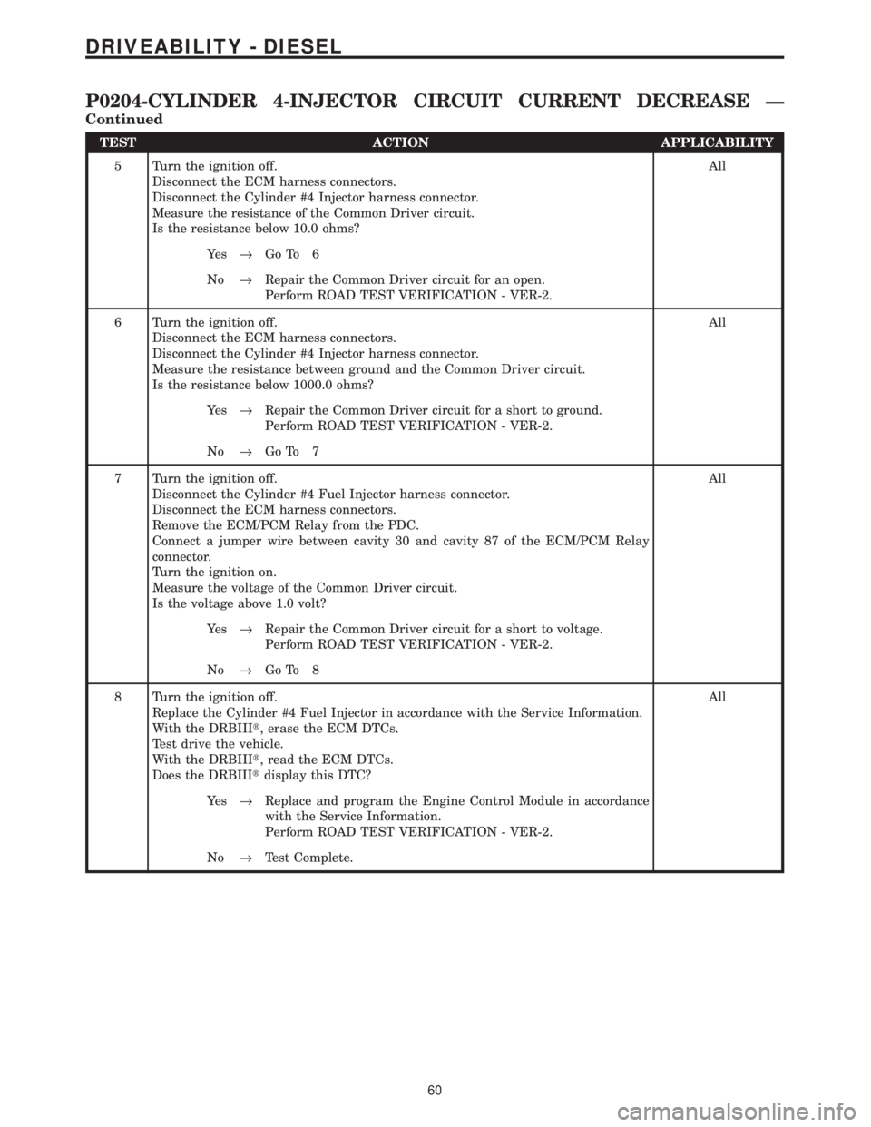
TEST ACTION APPLICABILITY
5 Turn the ignition off.
Disconnect the ECM harness connectors.
Disconnect the Cylinder #4 Injector harness connector.
Measure the resistance of the Common Driver circuit.
Is the resistance below 10.0 ohms?All
Ye s®Go To 6
No®Repair the Common Driver circuit for an open.
Perform ROAD TEST VERIFICATION - VER-2.
6 Turn the ignition off.
Disconnect the ECM harness connectors.
Disconnect the Cylinder #4 Injector harness connector.
Measure the resistance between ground and the Common Driver circuit.
Is the resistance below 1000.0 ohms?All
Ye s®Repair the Common Driver circuit for a short to ground.
Perform ROAD TEST VERIFICATION - VER-2.
No®Go To 7
7 Turn the ignition off.
Disconnect the Cylinder #4 Fuel Injector harness connector.
Disconnect the ECM harness connectors.
Remove the ECM/PCM Relay from the PDC.
Connect a jumper wire between cavity 30 and cavity 87 of the ECM/PCM Relay
connector.
Turn the ignition on.
Measure the voltage of the Common Driver circuit.
Is the voltage above 1.0 volt?All
Ye s®Repair the Common Driver circuit for a short to voltage.
Perform ROAD TEST VERIFICATION - VER-2.
No®Go To 8
8 Turn the ignition off.
Replace the Cylinder #4 Fuel Injector in accordance with the Service Information.
With the DRBIIIt, erase the ECM DTCs.
Test drive the vehicle.
With the DRBIIIt, read the ECM DTCs.
Does the DRBIIItdisplay this DTC?All
Ye s®Replace and program the Engine Control Module in accordance
with the Service Information.
Perform ROAD TEST VERIFICATION - VER-2.
No®Test Complete.
60
DRIVEABILITY - DIESEL
P0204-CYLINDER 4-INJECTOR CIRCUIT CURRENT DECREASE Ð
Continued
Page 1296 of 4284
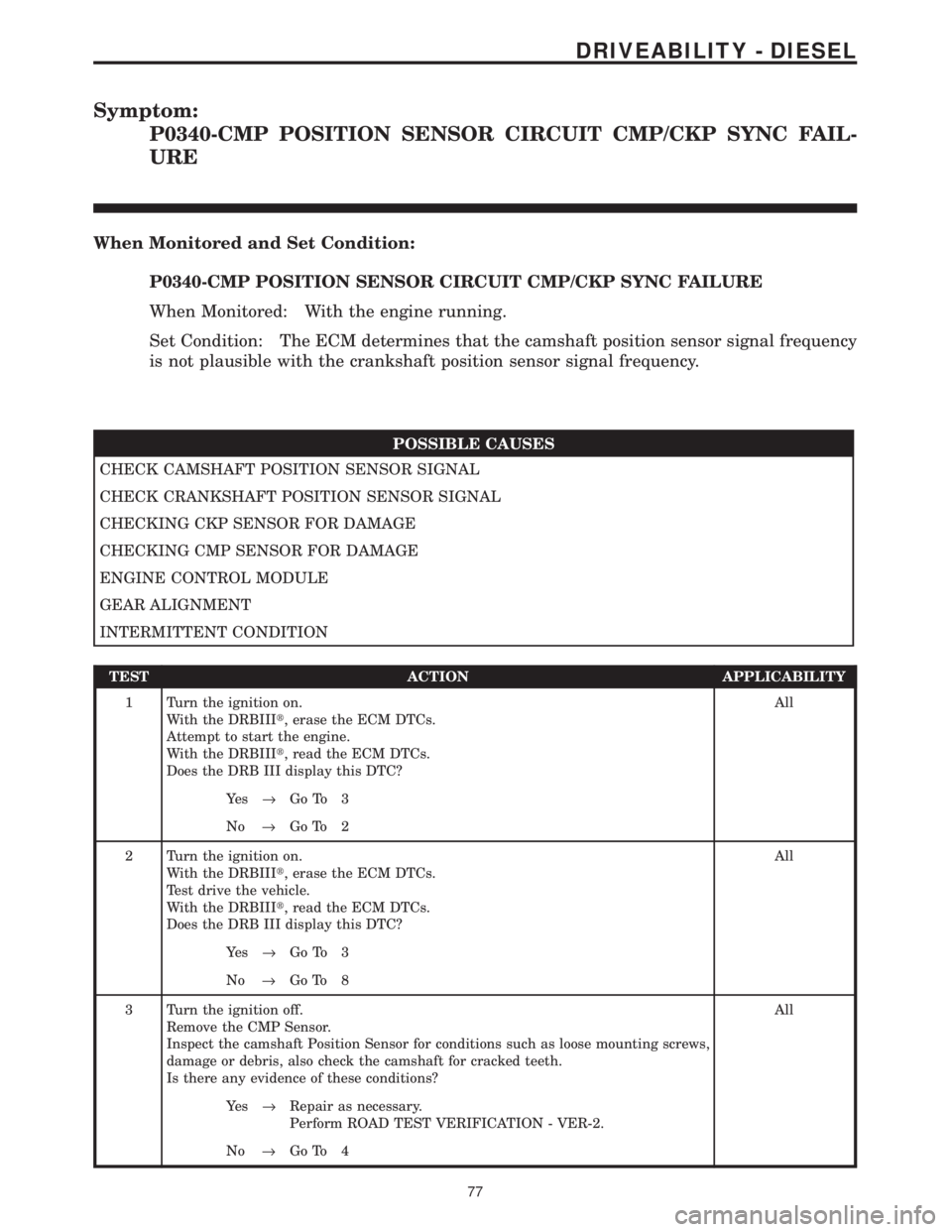
Symptom:
P0340-CMP POSITION SENSOR CIRCUIT CMP/CKP SYNC FAIL-
URE
When Monitored and Set Condition:
P0340-CMP POSITION SENSOR CIRCUIT CMP/CKP SYNC FAILURE
When Monitored: With the engine running.
Set Condition: The ECM determines that the camshaft position sensor signal frequency
is not plausible with the crankshaft position sensor signal frequency.
POSSIBLE CAUSES
CHECK CAMSHAFT POSITION SENSOR SIGNAL
CHECK CRANKSHAFT POSITION SENSOR SIGNAL
CHECKING CKP SENSOR FOR DAMAGE
CHECKING CMP SENSOR FOR DAMAGE
ENGINE CONTROL MODULE
GEAR ALIGNMENT
INTERMITTENT CONDITION
TEST ACTION APPLICABILITY
1 Turn the ignition on.
With the DRBIIIt, erase the ECM DTCs.
Attempt to start the engine.
With the DRBIIIt, read the ECM DTCs.
Does the DRB III display this DTC?All
Ye s®Go To 3
No®Go To 2
2 Turn the ignition on.
With the DRBIIIt, erase the ECM DTCs.
Test drive the vehicle.
With the DRBIIIt, read the ECM DTCs.
Does the DRB III display this DTC?All
Ye s®Go To 3
No®Go To 8
3 Turn the ignition off.
Remove the CMP Sensor.
Inspect the camshaft Position Sensor for conditions such as loose mounting screws,
damage or debris, also check the camshaft for cracked teeth.
Is there any evidence of these conditions?All
Ye s®Repair as necessary.
Perform ROAD TEST VERIFICATION - VER-2.
No®Go To 4
77
DRIVEABILITY - DIESEL