2001 CHRYSLER VOYAGER display
[x] Cancel search: displayPage 1222 of 4284
sponder ID message to the SKIM. The SKIM com-
pares the transponder ID message to the available
valid key codes in SKIM memory (8 key maximum
at any one time). After validating the ignition key,
the SKIM sends a PCI Bus message called a seed
request to the ECM, then waits for the ECM re-
sponse. If the ECM does not respond, the SKIM will
send the seed request again. After three failed
attempts, the SKIM will stop sending the seed
request and store a trouble code in memory. If the
ECM sends a seed response, the SKIM sends a
valid/invalid key message to the ECM. This is an
encrypted message that is generated using the
following:
VIN - Vehicle Identification Number.
Seed - This is a random number that is generated
by the ECM at each ignition key cycle.
The VIN and seed are two variables used in the
rolling code algorithm that encrypts the valid/
invalid key message. The ECM uses the rolling code
algorithm to receive, decode and respond to the
valid/invalid key message sent by the SKIM. After
sending the valid/invalid key message, the SKIM
waits 3.5 seconds for an ECM status message from
the ECM. If the ECM does not respond with a valid
key message to the SKIM, a fault is detected and a
code is stored.
The SKIS incorporates a warning lamp located in
the information center. The lamp receives switched
ignition voltage and is hardwired to the body con-
trol module. The lamp is actuated when the SKIM
sends a PCI Bus message to the body control
module requesting the lamp on. The body control
module then provides the ground for the lamp.
The SKIM will request lamp operation for the
following:
± bulb check at ignition on
± to alert the vehicle operator to a SKIS malfunc-
tion
± when the SKIM is in customer key programming
mode
For all faults except transponder faults the lamp
remains on steady. In the event of a transponder
fault the lamp will flash at a rate of 1Hz (once per
second). If a fault is present, the lamp will remain
on or flashing for the complete ignition cycle. If a
fault is stored in SKIM memory which prevents the
system from operating properly, the ECM will allow
the engine to start and idle for 2 seconds then stall.
This may occur up to six times. After the sixth
attempt, the ECM disables the starter relay until
the fault is corrected.
3.3 DIAGNOSTIC TROUBLE CODES
Each diagnostic trouble code (DTC) is diagnosed
by following a specific procedure. The diagnostic
test procedure contains step-by-step instruction fordetermining the cause of the DTC as well as no
trouble code problems. It is not necessary to per-
form all of the tests in this book to diagnose an
individual code.
Always begin diagnosis by reading the DTC's
using the DRBIIIt.
3.3.1 HARD CODE
A DTC that comes back within one cycle of the
ignition key is a hard code. This means that the
problem is current every time the ECM/SKIM
checks that circuit or function. Procedures in this
manual verify if the DTC is a hard code at the
beginning of each test. When the fault is not a hard
code, an intermittent test must be performed.
NOTE: If the DRBIIItdisplays faults for multiple
components (i.e. ECT, VSS, Oil Temp sensors) iden-
tify and check the shared circuits for possible prob-
lems before continuing (i.e. sensor grounds or 5-volt
supply circuits). Refer to the appropriate schematic
to identify shared circuits.
3.3.2 INTERMITTENT CODE
A DTC that is not current every time the ECM/
SKIM checks the circuit or function is an intermit-
tent code. Most intermittent DTCs are caused by
wiring or connector problems. Problems that come
and go like this are the most difficult to diagnose;
they must be looked for under specific conditions
that cause them. The following checks may assist
you in identifying a possible intermittent problem.
²Visually inspect the related wire harness connec-
tors. Look for broken, bent, pushed out, or cor-
roded terminals.
²Visually inspect the related wire harness. Look
for chafed, pierced, or partially broken wire.
²Refer to hotlines or technical service bulletins
that may apply.
NOTE: Electromagnetic (radio) interference can
cause an intermittent system malfunction. This
interference can interrupt communication between
the ignition key transponder and the SKIM.
3.3.3 ECM DIAGNOSTIC TROUBLE CODES
IMPORTANT NOTE:Before replacing the ECM
for a failed driver, control circuit or ground circuit,
be sure to check the related component/circuit in-
tegrity for failures not detected due to a double fault
in the circuit. Most ECM driver/control circuit fail-
ures are caused by internal failures to components
(i.e. relays and solenoids) and shorted circuits (i.e.
sensor pull-ups, drivers and ground circuits). These
faults are difficult to detect when a double fault has
occurred and only one DTC has set.
If the DRB displays faults for multiple compo-
nents (i.e. VSS, ECT, Batt Temp, etc.), identify and
3
GENERAL INFORMATION
Page 1225 of 4284
J1850 COMMUNICATION BUS SPI ERROR
J1850 COMMUNICATION BUS RECEIVE TIME-
OUT
J1850 COMMUNICATION BUS UNAUTHO-
RIZED RESET
EEPROM PLAUSIBILITY CHECKSUM ERROR
EEPROM PLAUSIBILITY VIN CHECKSUM
ERROR
EEPROM PLAUSIBILITY COMMUNICATION
ERROR
EEPROM PLAUSIBILITY WRITE ERROR
EEPROM PLAUSIBILITY VARIATION NUM-
BER ERROR
EEPROM PLAUSIBILITY CODE WORD IN-
CORRECT OR MISSING
SKIM SYSTEM SKIM ERROR
SKIM SYSTEM WRITE ACCESS TO EEPROM
FAILURE
SKIM SYSTEM INVALID SECRET KEY IN EE-
PROM
SKIM SYSTEM KEY COMMUNICATION
TIMED OUT
SKIM SYSTEM INVALID KEY CODE RE-
CEIVED
EEPROM RECOVERY OCCURRED
EEPROM REDUNDANT OVERRUN MONI-
TORING
EEPROM QUANTITY STOP
EEPROM COMMUNICATION ERROR
EEPROM COMMUNICATION NOT VERIFIED
ACC PEDAL POSITION SENSOR 1 CKT SIG-
NAL VOLTAGE TOO HIGH
ACC PEDAL POSITION SENSOR 1 CKT SIG-
NAL VOLTAGE TOO LOW
ACC PEDAL POSITION SENSOR 1 CKT SUP-
PLY VOLTAGE TOO HIGH OR LOW
ACC PEDAL POSITION SENSOR 1 CKT PLAU-
SIBILITY WITH POTENTIOMETER
ACC PEDAL POSITION SENSOR 1 CKT PLAU-
SIBILITY WITH BRAKE SWITCH
ACC PEDAL POSITION SENSOR 1 CKT PLAU-
SIBILITY
3.3.4 SKIM DIAGNOSTIC TROUBLE CODES
ANTENNA FAILURE
COP FAILURE
EEPROM FAILURE
PCM STATUS FAILURE
INTERNAL FAULT
RAM FAILURE
ROLLING CODE FAILURE
SERIAL LINK EXTERNAL FAULT
SERIAL LINK INTERNAL FAULT
STACK OVERFLOW FAILURE
TRANSPONDER COMMUNICATION FAILURE
TRANSPONDER CRC (CYCLIC REDUN-
DANCY CHECK) FAILURE
TRANSPONDER ID MISMATCHTRANSPONDER RESPONSE MISMATCH
VIN MISMATCH
3.3.5 HANDLING NO TROUBLE CODE
PROBLEMS
After reading Section 3.0 (System Description
and Functional Operation), you should have a bet-
ter understanding of the theory and operation of the
on-board diagnostics, and how this relates to the
diagnosis of a vehicle that may have a driveability-
related symptom or complaint.
3.4 USING THE DRBIIIT
Refer to the DRBIIItuser 's guide for instructions
and assistance with reading the DTCs, erasing the
DTCs, lab scope usage and other DRBIIItfunc-
tions.
3.4.1 DRBIIITDOES NOT POWER UP
If the LEDs do not light or no sound is emitted at
start up, check for loose cable connections or a bad
cable. Check the vehicle battery voltage at data link
connector cavity 16. A minimum of 11.0 volts is
required to adequately power the DRB. Check for
proper ground connection at data link connector
cavities 4 and 5.
If all connections are proper between the
DRBIIItand the vehicle or other devices, and the
vehicle battery is fully charged, an inoperative
DRBIIItmay be the result of a faulty cable or
vehicle wiring. For a blank screen, refer to the
appropriate diagnostic manual.
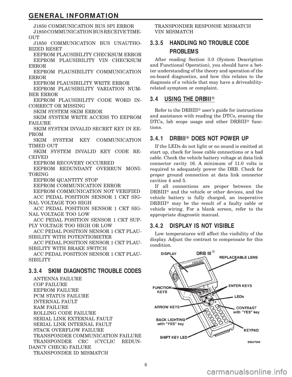
3.4.2 DISPLAY IS NOT VISIBLE
Low temperatures will affect the visibility of the
display. Adjust the contrast to compensate for this
condition.
6
GENERAL INFORMATION
Page 1229 of 4284
Symptom:
*NO RESPONSE FROM ECM (PCI BUS) - DIESEL ONLY
POSSIBLE CAUSES
ECM PCI NO RESPONSE
PCI BUS CIRCUIT OPEN
ENGINE CONTROL MODULE
TEST ACTION APPLICABILITY
1 Turn the ignition on.
NOTE: As soon as one or more module communicates with the DRB, answer
the question.
With the DRB, enter Body then Body Computer.
With the DRB, enter Anti-Lock Brakes.
With the DRB, enter Body then Electro/Mechanical Cluster (MIC).
With the DRB, enter Passive Restraints then Airbag.
Were you able to establish communications with any of the modules?All
Ye s®Go To 2
No®Refer to symptom PCI Bus Communication Failure in the Com-
munications category.
Perform ROAD TEST VERIFICATION - VER-2.
2 With the DRB read ECM Diagnostic Trouble Codes. This is to ensure power and
grounds to the ECM are operational.
NOTE: If the DRB will not read ECM DTC's, follow the NO RESPONSE TO
ECM (SCI only) symptom path, if vehicle will start. For NO START Condi-
tions follow the no start symptom in the Starting category.
Turn the ignition off.
Disconnect the ECM harness connectors.
Use Scope input cable CH7058, Cable to Probe adapter CH7062, and the red and
black test probes.
Connect the scope input cable to the channel one connector on the DRB. Attach the
red and black leads and the cable to probe adapter to the scope input cable.
With the DRBIIItselect Pep Module Tools.
Select lab scope.
Select Live Data.
Select 12 volt square wave.
Press F2 for Scope.
Press F2 and use the down arrow to set voltage range to 20 volts. Press F2 again
when complete.
Connect the Black lead to ground. Connect the Red lead to the PCI Bus circuit in the
ECM connector.
Turn the ignition on.
Observe the voltage display on the DRB Lab Scope.
Does the voltage pulse from 0 to approximately 7.5 volts?All
Ye s®Replace and program the Engine Control Module in accordance
with the Service Information.
Perform ROAD TEST VERIFICATION - VER-2.
No®Repair the PCI Bus circuit for an open.
Perform ROAD TEST VERIFICATION - VER-2.
10
COMMUNICATION
Page 1233 of 4284
POSSIBLE CAUSES
MAF SENSOR SIGNAL CIRCUIT OPEN
5-VOLT SUPPLY CIRCUIT SHORTED TO THE SENSOR GROUND CIRCUIT
5-VOLT SUPPLY CIRCUIT SHORTED TO THE SENSOR GROUND CIRCUIT
MAF SENSOR SIGNAL CIRCUIT SHORTED TO GROUND
5-VOLT SUPPLY CIRCUIT SHORTED TO GROUND
5-VOLT SUPPLY CIRCUIT SHORTED TO GROUND
ECM SENSOR GROUND CIRCUIT OPEN
MAF SENSOR SIGNAL CIRCUIT SHORTED TO THE SENSOR GROUND CIRCUIT
5-VOLT SUPPLY CIRCUIT SHORTED TO VOLTAGE
5-VOLT SUPPLY CIRCUIT SHORTED TO VOLTAGE
MAF SENSOR CIRCUIT SHORTED TO VOLTAGE
ECM - MAF SENSOR SIGNAL CIRCUIT
TEST ACTION APPLICABILITY
1NOTE: If DTC P0641 or P0651 is present with this DTC, diagnose DTCs
P0641 and P0651 before diagnosing this DTC.
NOTE: Inspect the turbocharger inlet tube between the MAF Sensor and the
turbocharger for damage, restriction or poor connection. Any of these
conditions can cause a MAF Plausibility DTC.
Turn the ignition on.
With the DRBIIIt, erase the ECM DTCs.
Test drive the vehicle.
With the DRBIIIt, read the ECM DTCs.
Does the DRB III display a Mass Air Flow Sensor DTC?All
Ye s®Go To 2
No®Go To 20
2 Turn the ignition off.
Disconnect the MAF Sensor harness connector.
Turn the ignition on.
Measure the voltage of the 5-volt Supply circuit in MAF Sensor harness connector.
Is the voltage between 4.7 and 5.3 volts?All
Ye s®Go To 3
No®Go To 13
14
DRIVEABILITY - DIESEL
P0100-MASS AIR FLOW SENSOR PLAUSIBILITY ÐContinued
Page 1234 of 4284
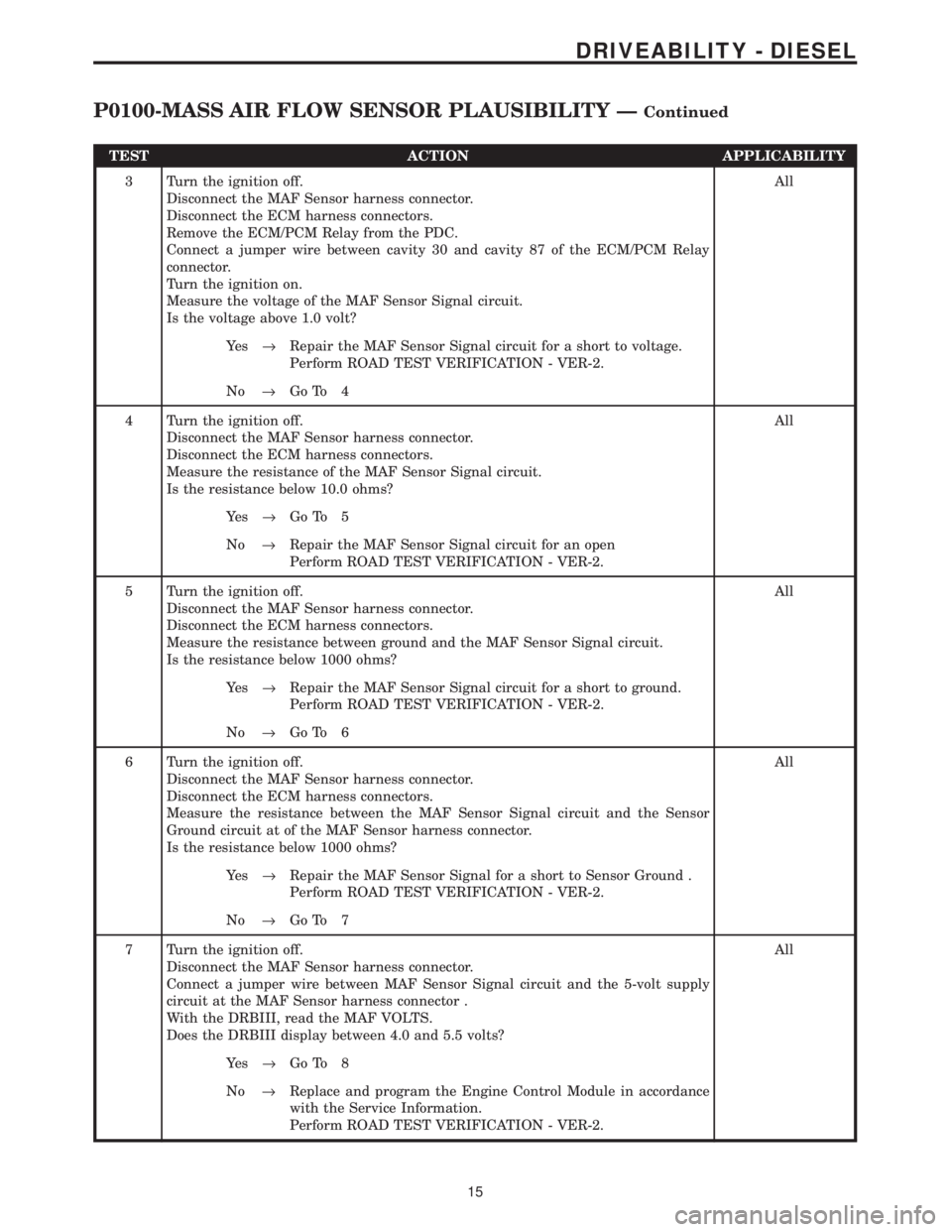
TEST ACTION APPLICABILITY
3 Turn the ignition off.
Disconnect the MAF Sensor harness connector.
Disconnect the ECM harness connectors.
Remove the ECM/PCM Relay from the PDC.
Connect a jumper wire between cavity 30 and cavity 87 of the ECM/PCM Relay
connector.
Turn the ignition on.
Measure the voltage of the MAF Sensor Signal circuit.
Is the voltage above 1.0 volt?All
Ye s®Repair the MAF Sensor Signal circuit for a short to voltage.
Perform ROAD TEST VERIFICATION - VER-2.
No®Go To 4
4 Turn the ignition off.
Disconnect the MAF Sensor harness connector.
Disconnect the ECM harness connectors.
Measure the resistance of the MAF Sensor Signal circuit.
Is the resistance below 10.0 ohms?All
Ye s®Go To 5
No®Repair the MAF Sensor Signal circuit for an open
Perform ROAD TEST VERIFICATION - VER-2.
5 Turn the ignition off.
Disconnect the MAF Sensor harness connector.
Disconnect the ECM harness connectors.
Measure the resistance between ground and the MAF Sensor Signal circuit.
Is the resistance below 1000 ohms?All
Ye s®Repair the MAF Sensor Signal circuit for a short to ground.
Perform ROAD TEST VERIFICATION - VER-2.
No®Go To 6
6 Turn the ignition off.
Disconnect the MAF Sensor harness connector.
Disconnect the ECM harness connectors.
Measure the resistance between the MAF Sensor Signal circuit and the Sensor
Ground circuit at of the MAF Sensor harness connector.
Is the resistance below 1000 ohms?All
Ye s®Repair the MAF Sensor Signal for a short to Sensor Ground .
Perform ROAD TEST VERIFICATION - VER-2.
No®Go To 7
7 Turn the ignition off.
Disconnect the MAF Sensor harness connector.
Connect a jumper wire between MAF Sensor Signal circuit and the 5-volt supply
circuit at the MAF Sensor harness connector .
With the DRBIII, read the MAF VOLTS.
Does the DRBIII display between 4.0 and 5.5 volts?All
Ye s®Go To 8
No®Replace and program the Engine Control Module in accordance
with the Service Information.
Perform ROAD TEST VERIFICATION - VER-2.
15
DRIVEABILITY - DIESEL
P0100-MASS AIR FLOW SENSOR PLAUSIBILITY ÐContinued
Page 1244 of 4284

TEST ACTION APPLICABILITY
3 Turn the ignition off.
Disconnect the ECM harness connectors.
Disconnect the Boost Pressure/IAT Sensor harness connector.
Measure the resistance of the Intake Air Temperature Sensor Signal circuit.
Is the resistance below 5.0 ohms?All
Ye s®Go To 4
No®Repair the Intake Air Temperature Sensor Signal circuit for an
open.
Perform ROAD TEST VERIFICATION - VER-2.
4 Turn the ignition off.
Disconnect the Boost Pressure/IAT Sensor harness connector.
Connect a jumper wire between the IAT Sensor Signal and IAT Sensor Ground
circuits in the Boost Pressure/IAT Sensor harness connector.
Turn the ignition on.
Monitor the DRB for ECM DTCs.
Does the DRB display P0110 INTAKE AIR TEMP. SENSOR CIRCUIT SIGNAL
VOLTAGE TOO LOW?All
Ye s®Replace the Turbocharger Boost Pressure/Intake Air Tempera-
ture Sensor.
Perform ROAD TEST VERIFICATION - VER-2.
No®Go To 5
5 Turn the ignition off.
Disconnect the Boost Pressure/IAT Sensor harness connector.
Disconnect the ECM harness connectors.
Measure the resistance of the Sensor Ground circuit between the ECM harness
connector and the Boost Pressure Sensor harness connector.
Monitor the DRB for ECM DTCs.
Is the resistance below 10.0 ohms?All
Ye s®Replace and program the Engine Control Module in accordance
with the Service Information.
Perform ROAD TEST VERIFICATION - VER-2.
No®Repair the Intake Air Temperature Sensor Ground circuit for an
open.
Perform ROAD TEST VERIFICATION - VER-2.
25
DRIVEABILITY - DIESEL
P0110-INTAKE AIR TEMP SENSOR CIRCUIT SIGNAL VOLTAGE TOO
HIGH Ð
Continued
Page 1246 of 4284
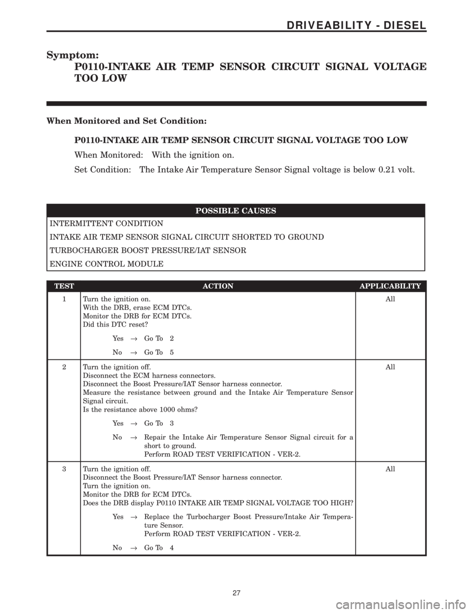
Symptom:
P0110-INTAKE AIR TEMP SENSOR CIRCUIT SIGNAL VOLTAGE
TOO LOW
When Monitored and Set Condition:
P0110-INTAKE AIR TEMP SENSOR CIRCUIT SIGNAL VOLTAGE TOO LOW
When Monitored: With the ignition on.
Set Condition: The Intake Air Temperature Sensor Signal voltage is below 0.21 volt.
POSSIBLE CAUSES
INTERMITTENT CONDITION
INTAKE AIR TEMP SENSOR SIGNAL CIRCUIT SHORTED TO GROUND
TURBOCHARGER BOOST PRESSURE/IAT SENSOR
ENGINE CONTROL MODULE
TEST ACTION APPLICABILITY
1 Turn the ignition on.
With the DRB, erase ECM DTCs.
Monitor the DRB for ECM DTCs.
Did this DTC reset?All
Ye s®Go To 2
No®Go To 5
2 Turn the ignition off.
Disconnect the ECM harness connectors.
Disconnect the Boost Pressure/IAT Sensor harness connector.
Measure the resistance between ground and the Intake Air Temperature Sensor
Signal circuit.
Is the resistance above 1000 ohms?All
Ye s®Go To 3
No®Repair the Intake Air Temperature Sensor Signal circuit for a
short to ground.
Perform ROAD TEST VERIFICATION - VER-2.
3 Turn the ignition off.
Disconnect the Boost Pressure/IAT Sensor harness connector.
Turn the ignition on.
Monitor the DRB for ECM DTCs.
Does the DRB display P0110 INTAKE AIR TEMP SIGNAL VOLTAGE TOO HIGH?All
Ye s®Replace the Turbocharger Boost Pressure/Intake Air Tempera-
ture Sensor.
Perform ROAD TEST VERIFICATION - VER-2.
No®Go To 4
27
DRIVEABILITY - DIESEL
Page 1266 of 4284
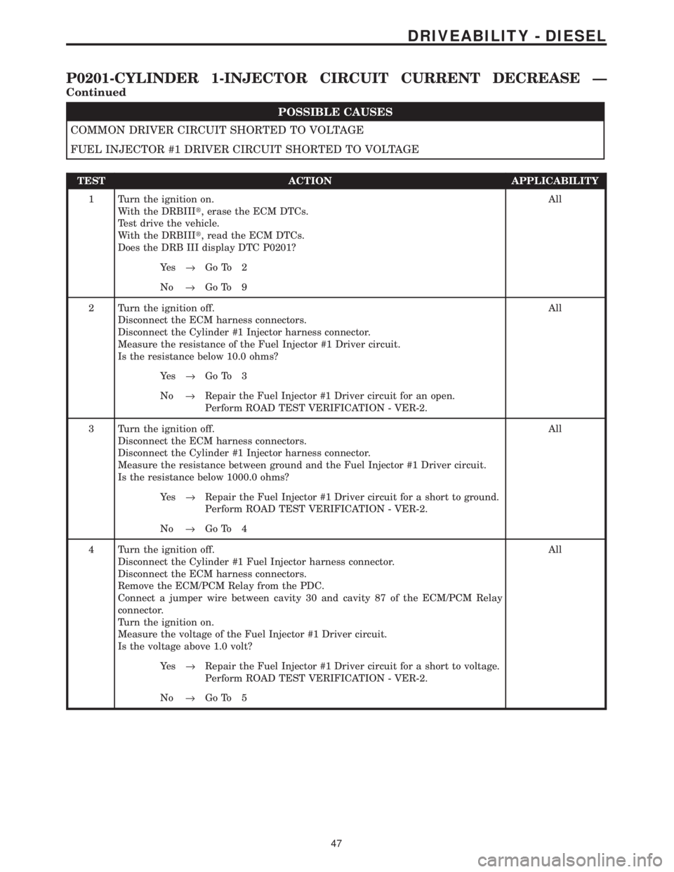
POSSIBLE CAUSES
COMMON DRIVER CIRCUIT SHORTED TO VOLTAGE
FUEL INJECTOR #1 DRIVER CIRCUIT SHORTED TO VOLTAGE
TEST ACTION APPLICABILITY
1 Turn the ignition on.
With the DRBIIIt, erase the ECM DTCs.
Test drive the vehicle.
With the DRBIIIt, read the ECM DTCs.
Does the DRB III display DTC P0201?All
Ye s®Go To 2
No®Go To 9
2 Turn the ignition off.
Disconnect the ECM harness connectors.
Disconnect the Cylinder #1 Injector harness connector.
Measure the resistance of the Fuel Injector #1 Driver circuit.
Is the resistance below 10.0 ohms?All
Ye s®Go To 3
No®Repair the Fuel Injector #1 Driver circuit for an open.
Perform ROAD TEST VERIFICATION - VER-2.
3 Turn the ignition off.
Disconnect the ECM harness connectors.
Disconnect the Cylinder #1 Injector harness connector.
Measure the resistance between ground and the Fuel Injector #1 Driver circuit.
Is the resistance below 1000.0 ohms?All
Ye s®Repair the Fuel Injector #1 Driver circuit for a short to ground.
Perform ROAD TEST VERIFICATION - VER-2.
No®Go To 4
4 Turn the ignition off.
Disconnect the Cylinder #1 Fuel Injector harness connector.
Disconnect the ECM harness connectors.
Remove the ECM/PCM Relay from the PDC.
Connect a jumper wire between cavity 30 and cavity 87 of the ECM/PCM Relay
connector.
Turn the ignition on.
Measure the voltage of the Fuel Injector #1 Driver circuit.
Is the voltage above 1.0 volt?All
Ye s®Repair the Fuel Injector #1 Driver circuit for a short to voltage.
Perform ROAD TEST VERIFICATION - VER-2.
No®Go To 5
47
DRIVEABILITY - DIESEL
P0201-CYLINDER 1-INJECTOR CIRCUIT CURRENT DECREASE Ð
Continued