2001 CHRYSLER VOYAGER display
[x] Cancel search: displayPage 1013 of 4284
Symptom:
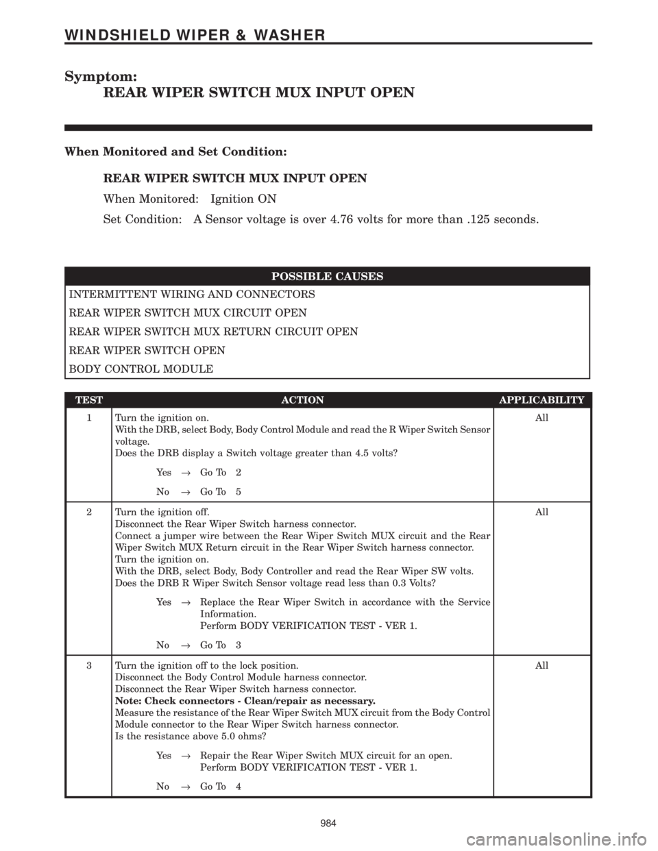
REAR WIPER SWITCH MUX INPUT OPEN
When Monitored and Set Condition:
REAR WIPER SWITCH MUX INPUT OPEN
When Monitored: Ignition ON
Set Condition: A Sensor voltage is over 4.76 volts for more than .125 seconds.
POSSIBLE CAUSES
INTERMITTENT WIRING AND CONNECTORS
REAR WIPER SWITCH MUX CIRCUIT OPEN
REAR WIPER SWITCH MUX RETURN CIRCUIT OPEN
REAR WIPER SWITCH OPEN
BODY CONTROL MODULE
TEST ACTION APPLICABILITY
1 Turn the ignition on.
With the DRB, select Body, Body Control Module and read the R Wiper Switch Sensor
voltage.
Does the DRB display a Switch voltage greater than 4.5 volts?All
Ye s®Go To 2
No®Go To 5
2 Turn the ignition off.
Disconnect the Rear Wiper Switch harness connector.
Connect a jumper wire between the Rear Wiper Switch MUX circuit and the Rear
Wiper Switch MUX Return circuit in the Rear Wiper Switch harness connector.
Turn the ignition on.
With the DRB, select Body, Body Controller and read the Rear Wiper SW volts.
Does the DRB R Wiper Switch Sensor voltage read less than 0.3 Volts?All
Ye s®Replace the Rear Wiper Switch in accordance with the Service
Information.
Perform BODY VERIFICATION TEST - VER 1.
No®Go To 3
3 Turn the ignition off to the lock position.
Disconnect the Body Control Module harness connector.
Disconnect the Rear Wiper Switch harness connector.
Note: Check connectors - Clean/repair as necessary.
Measure the resistance of the Rear Wiper Switch MUX circuit from the Body Control
Module connector to the Rear Wiper Switch harness connector.
Is the resistance above 5.0 ohms?All
Ye s®Repair the Rear Wiper Switch MUX circuit for an open.
Perform BODY VERIFICATION TEST - VER 1.
No®Go To 4
984
WINDSHIELD WIPER & WASHER
Page 1015 of 4284
Symptom:
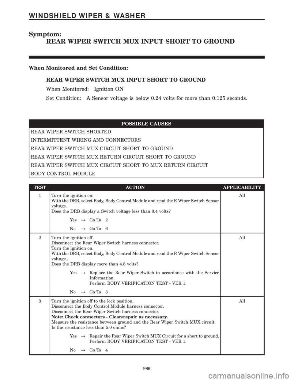
REAR WIPER SWITCH MUX INPUT SHORT TO GROUND
When Monitored and Set Condition:
REAR WIPER SWITCH MUX INPUT SHORT TO GROUND
When Monitored: Ignition ON
Set Condition: A Sensor voltage is below 0.24 volts for more than 0.125 seconds.
POSSIBLE CAUSES
REAR WIPER SWITCH SHORTED
INTERMITTENT WIRING AND CONNECTORS
REAR WIPER SWITCH MUX CIRCUIT SHORT TO GROUND
REAR WIPER SWITCH MUX RETURN CIRCUIT SHORT TO GROUND
REAR WIPER SWITCH MUX CIRCUIT SHORT TO MUX RETURN CIRCUIT
BODY CONTROL MODULE
TEST ACTION APPLICABILITY
1 Turn the ignition on.
With the DRB, select Body, Body Control Module and read the R Wiper Switch Sensor
voltage.
Does the DRB display a Switch voltage less than 0.4 volts?All
Ye s®Go To 2
No®Go To 6
2 Turn the ignition off.
Disconnect the Rear Wiper Switch harness connector.
Turn the ignition on.
With the DRB, select Body, Body Control Module and read the R Wiper Switch Sensor
voltage..
Does the DRB display more than 4.8 volts?All
Ye s®Replace the Rear Wiper Switch in accordance with the Service
Information.
Perform BODY VERIFICATION TEST - VER 1.
No®Go To 3
3 Turn the ignition off to the lock position.
Disconnect the Body Control Module harness connector.
Disconnect the Rear Wiper Switch harness connector.
Note: Check connectors - Clean/repair as necessary.
Measure the resistance between ground and the Rear Wiper Switch MUX circuit.
Is the resistance less than 5.0 ohms?All
Ye s®Repair the Rear Wiper Switch MUX Circuit for a short to ground.
Perform BODY VERIFICATION TEST - VER 1.
No®Go To 4
986
WINDSHIELD WIPER & WASHER
Page 1017 of 4284
Verification Tests
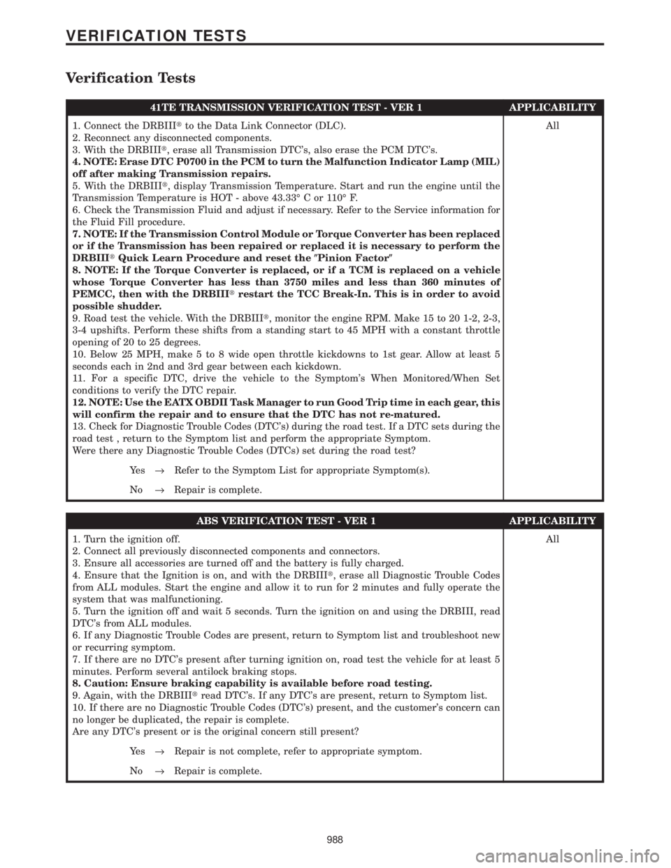
41TE TRANSMISSION VERIFICATION TEST - VER 1 APPLICABILITY
1. Connect the DRBIIItto the Data Link Connector (DLC).
2. Reconnect any disconnected components.
3. With the DRBIIIt, erase all Transmission DTC's, also erase the PCM DTC's.
4. NOTE: Erase DTC P0700 in the PCM to turn the Malfunction Indicator Lamp (MIL)
off after making Transmission repairs.
5. With the DRBIIIt, display Transmission Temperature. Start and run the engine until the
Transmission Temperature is HOT - above 43.33É C or 110É F.
6. Check the Transmission Fluid and adjust if necessary. Refer to the Service information for
the Fluid Fill procedure.
7. NOTE: If the Transmission Control Module or Torque Converter has been replaced
or if the Transmission has been repaired or replaced it is necessary to perform the
DRBIIItQuick Learn Procedure and reset the(Pinion Factor(
8. NOTE: If the Torque Converter is replaced, or if a TCM is replaced on a vehicle
whose Torque Converter has less than 3750 miles and less than 360 minutes of
PEMCC, then with the DRBIIItrestart the TCC Break-In. This is in order to avoid
possible shudder.
9. Road test the vehicle. With the DRBIIIt, monitor the engine RPM. Make 15 to 20 1-2, 2-3,
3-4 upshifts. Perform these shifts from a standing start to 45 MPH with a constant throttle
opening of 20 to 25 degrees.
10. Below 25 MPH, make 5 to 8 wide open throttle kickdowns to 1st gear. Allow at least 5
seconds each in 2nd and 3rd gear between each kickdown.
11. For a specific DTC, drive the vehicle to the Symptom's When Monitored/When Set
conditions to verify the DTC repair.
12. NOTE: Use the EATX OBDII Task Manager to run Good Trip time in each gear, this
will confirm the repair and to ensure that the DTC has not re-matured.
13. Check for Diagnostic Trouble Codes (DTC's) during the road test. If a DTC sets during the
road test , return to the Symptom list and perform the appropriate Symptom.
Were there any Diagnostic Trouble Codes (DTCs) set during the road test?All
Ye s®Refer to the Symptom List for appropriate Symptom(s).
No®Repair is complete.
ABS VERIFICATION TEST - VER 1 APPLICABILITY
1. Turn the ignition off.
2. Connect all previously disconnected components and connectors.
3. Ensure all accessories are turned off and the battery is fully charged.
4. Ensure that the Ignition is on, and with the DRBIIIt, erase all Diagnostic Trouble Codes
from ALL modules. Start the engine and allow it to run for 2 minutes and fully operate the
system that was malfunctioning.
5. Turn the ignition off and wait 5 seconds. Turn the ignition on and using the DRBIII, read
DTC's from ALL modules.
6. If any Diagnostic Trouble Codes are present, return to Symptom list and troubleshoot new
or recurring symptom.
7. If there are no DTC's present after turning ignition on, road test the vehicle for at least 5
minutes. Perform several antilock braking stops.
8. Caution: Ensure braking capability is available before road testing.
9. Again, with the DRBIIItread DTC's. If any DTC's are present, return to Symptom list.
10. If there are no Diagnostic Trouble Codes (DTC's) present, and the customer's concern can
no longer be duplicated, the repair is complete.
Are any DTC's present or is the original concern still present?All
Ye s®Repair is not complete, refer to appropriate symptom.
No®Repair is complete.
988
VERIFICATION TESTS
Page 1019 of 4284
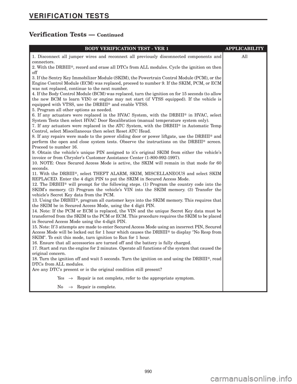
BODY VERIFICATION TEST - VER 1 APPLICABILITY
1. Disconnect all jumper wires and reconnect all previously disconnected components and
connectors.
2. With the DRBIIIt, record and erase all DTCs from ALL modules. Cycle the ignition on then
off
3. If the Sentry Key Immobilizer Module (SKIM), the Powertrain Control Module (PCM), or the
Engine Control Module (ECM) was replaced, proceed to number 9. If the SKIM, PCM, or ECM
was not replaced, continue to the next number.
4. If the Body Control Module (BCM) was replaced, turn the ignition on for 15 seconds (to allow
the new BCM to learn VIN) or engine may not start (if VTSS equipped). If the vehicle is
equipped with VTSS, use the DRBIIItand enable VTSS.
5. Program all other options as needed.
6. If any actuators were replaced in the HVAC System, with the DRBIIItin HVAC, select
System Tests then select HVAC Door Recalibration (manual temperature system only).
7. If any actuators were replaced in the ATC System, with the DRBIIItin Automatic Temp
Control, select Miscellaneous then select Reset ATC Head.
8. If any repairs were made to the power sliding door or power liftgate, use the DRBIIItand
perform the open and close system tests. Observe the instructions on the DRBIIItscreen.
Proceed to number 16.
9. Obtain the vehicle's unique PIN assigned to it's original SKIM from either the vehicle's
invoice or from Chrysler's Customer Assistance Center (1-800-992-1997).
10. NOTE: Once Secured Access Mode is active, the SKIM will remain in that mode for 60
seconds.
11. With the DRBIIIt, select THEFT ALARM, SKIM, MISCELLANEOUS and select SKIM
REPLACED. Enter the 4 digit PIN to put the SKIM in Secured Access Mode.
12. The DRBIIItwill prompt for the following steps. (1) Program the country code into the
SKIM's memory. (2) Program the vehicle's VIN into the SKIM memory. (3) Transfer the
vehicle's Secret Key data from the PCM.
13. Using the DRBIIIt, program all customer keys into the SKIM memory. This requires that
the SKIM be in Secured Access Mode, using the 4 digit PIN.
14. Note: If the PCM or ECM is replaced, the VIN and the unique Secret Key data must be
transferred from the SKIM to the PCM or ECM. This procedure requires the SKIM to be placed
in Secured Access Mode using the 4-digit PIN.
15. Note: If 3 attempts are made to enter Secured Access Mode using an incorrect PIN, Secured
Access Mode will be locked out for 1 hour which causes the DRBIIItto display9No Resp from
SKIM9. To exit this mode, turn ignition to Run for 1 hour.
16. Ensure that all accessories are turned off and the battery is fully charged.
17. Start and run the engine for 2 minutes. Operate all functions of the system that caused the
original concern.
18. Turn the ignition off and wait 5 seconds. Turn the ignition on and using the DRBIIIt, read
DTCs from ALL modules.
Are any DTC's present or is the original condition still present?All
Ye s®Repair is not complete, refer to the appropriate symptom.
No®Repair is complete.
990
VERIFICATION TESTS
Verification Tests ÐContinued
Page 1022 of 4284
ROAD TEST VERIFICATION - VER-2 APPLICABILITY
1. Inspect the vehicle to ensure that all engine components are properly installed and
connected. Reassemble and reconnect components as necessary.
2. If this verification procedure is being performed after a non-DTC test, perform steps 3 and
4.
3. Check to see if the initial symptom still exists. If there are no trouble codes and the symptom
no longer exists, the repair was successful and testing is now complete.
4. If the initial or another symptom exists, the repair is not complete. Check all pertinent
Technical Service Bulletins (TSBs) and return to the Symptom List if necessary.
5. For previously read DTCs that have not been dealt with, return to the Symptom List and
follow the diagnostic path for that DTC; otherwise, continue.
6. If the Engine Control Module (ECM) (diesel only) or Powertrain Control Module (PCM) has
not been changed, perform steps 7 and 8, otherwise, continue with step 9.
7. With the DRB, erase all diagnostic trouble codes (DTCs), then disconnect the DRB.
8. Turn the ignition off for at least 10 seconds.
9. Ensure no DTCs remain by performing steps 10 through 13.
10. Road test the vehicle. For some of the road test, go at least 64 km/h (40 MPH). If this test
is for an A/C Relay Control Circuit, drive the vehicle for at least 5 minutes with the A/C on.
11. At some point, stop the vehicle and turn the engine off for at least 10 seconds, then restart
the engine and continue.
12. Upon completion of the road test, turn the engine off and check for DTCs with the DRB.
13. If the repaired DTC has reset, the repair is not complete. Check for any pertinent Technical
Service Bulletins (TSBs) and return to the Symptom List. If there are no DTCs, the repair was
successful and is now complete.
Are any DTCs or symptoms remaining?All
Ye s®Repair is not complete, refer to appropriate symptom.
No®Repair is complete.
SKIS VERIFICATION APPLICABILITY
1. Reconnect all previously disconnected components and connectors.
2. Obtain the vehicle's unique Personal Identification Number (PIN) assigned to it's original
SKIM. This number can be obtained from the vehicle's invoice or Chrysler's Customer Center
(1-800-992-1997).
3. NOTE: When entering the PIN, care should be taken because the SKIM will only
allow 3 consecutive attempts to enter the correct PIN. If 3 consecutive incorrect
PIN's are entered the SKIM will Lock Out the DRB III for 1 hour.
4. To exit Lock Out mode, the ignition key must remain in the Run position continually for 1
hour. Turn off all accessories and connect a battery charger if necessary.
5. With the DRB III, select Theft Alarm, SKIM and Miscellaneous. Then select desired
procedure and follow the steps that will be displayed.
6. If the SKIM has been replaced, ensure all of the vehicle ignition keys are programmed to the
new SKIM.
7. NOTE: Prior to returning vehicle to the costumer, perform a module scan to be
sure that all DTC's are erased. Erase any DTC's that are found.
8. With the DRB III erase all DTC's. Perform 5 ignition key cycles leaving the key on for at least
90 seconds per cycle.
9. With the DRB III, read the SKIM DTC's.
Are there any SKIM DTC's?All
Ye s®Repair is not complete, refer to appropriate symptom.
No®Repair is complete.
993
VERIFICATION TESTS
Verification Tests ÐContinued
Page 1156 of 4284
TABLE OF CONTENTS
1.0 INTRODUCTION.........................................................1
1.1SYSTEM COVERAGE...............................................1
1.2SIX-STEP TROUBLESHOOTING PROCEDURE..........................1
2.0 IDENTIFICATION OF SYSTEM.............................................1
3.0 SYSTEM DESCRIPTION AND FUNCTIONAL OPERATION......................1
3.1TEVES MARK 20 SYSTEM DESCRIPTION..............................1
3.2TRACTION CONTROL SYSTEM (TCS) DESCRIPTION....................1
3.3SYSTEM COMPONENTS.............................................2
3.3.1ABS AND BRAKE WARNING INDICATORS.......................2
3.3.2CONTROLLER ANTILOCK BRAKE (CAB)........................2
3.3.3HYDRAULIC CONTROL UNIT..................................3
3.3.4SWITCHES/SENSORS........................................3
3.3.5SYSTEM INITIALIZATION.....................................3
3.3.6DIAGNOSTIC MODE.........................................4
3.4DIAGNOSTIC TROUBLE CODES......................................4
3.5DRBIIITERROR MESSAGES AND BLANK SCREEN......................4
3.5.1DRBIIITDOES NOT POWER UP................................4
3.5.2DISPLAY IS NOT VISIBLE.....................................4
4.0 DISCLAIMERS, SAFETY, WARNINGS.......................................5
4.1DISCLAIMERS......................................................5
4.2SAFETY...........................................................5
4.2.1TECHNICIAN SAFETY INFORMATION...........................5
4.2.2VEHICLE PREPARATION FOR TESTING.........................5
4.2.3SERVICING SUB-ASSEMBLIES................................5
4.2.4DRBIIITSAFETY INFORMATION...............................5
4.3WARNINGS........................................................6
4.3.1VEHICLE DAMAGE WARNINGS................................6
4.3.2ROAD TESTING A COMPLAINT VEHICLE........................6
4.4DIAGNOSIS........................................................6
5.0 REQUIRED TOOLS AND EQUIPMENT......................................6
6.0 GLOSSARY OF TERMS...................................................7
7.0 DIAGNOSTIC INFORMATION AND PROCEDURES............................9
BRAKES (CAB)
BUS SYSTEM COMMUNICATION FAILURE.................................10
CAB INTERNAL FAILURE................................................11
CLUSTER LAMP FAILURE................................................12
LEFT FRONT SENSOR CIRCUIT FAILURE..................................14
LEFT REAR SENSOR CIRCUIT FAILURE...................................14
RIGHT FRONT SENSOR CIRCUIT FAILURE.................................14
RIGHT REAR SENSOR CIRCUIT FAILURE..................................14
LEFT FRONT WHEEL SPEED SIGNAL FAILURE.............................17
LEFT REAR WHEEL SPEED SIGNAL FAILURE..............................19
PUMP CIRCUIT FAILURE................................................21
RIGHT FRONT WHEEL SPEED SIGNAL FAILURE............................24
i
Page 1158 of 4284
1.0 INTRODUCTION
The procedures contained in this manual include
all the specifications, instructions, and graphics
needed to diagnose Mark 20 Antilock Braking Sys-
tem (ABS) and Mark 20 Antilock Braking System
with Traction Control. The diagnostics in this man-
ual are based on the failure condition or symptom
being present at time of diagnosis.
Please follow the recommendations below when
choosing your diagnostic path.
1. First make sure the DRBIIItis communicating
with the CAB. If the DRBIIItdisplays a ªNo
Responseº condition, you must diagnose that
first.
2. Read DTC's (diagnostic trouble codes) with the
DRBIIIt.
3. If no DTC's are present, identify the customer
complaint.
4. Once the DTC or customer complaint is identi-
fied, locate the matching test in the Table of
Contents and begin to diagnose the symptom.
All component location views are in Section 8.0.
All connector pinouts are in Section 9.0. All sche-
matics are in Section 10.0.
An * placed before the symptom description indi-
cates a concern with no associated DTC.
When repairs are required, refer to the appropri-
ate service manual for the proper removal and
repair procedure.
Diagnostic procedures change every year. New
diagnostic systems may be added; carry over sys-
tems may be enhanced. READ THIS MANUAL
BEFORE TRYING TO DIAGNOSE A VEHICLE
CODE. It is recommended that you review the
entire manual to become familiar with all new and
changed diagnostic procedures.
After using this book, if you have any comments
or recommendations, please fill out the form at the
back of the book and mail it back to us.
1.1 SYSTEM COVERAGE
This diagnostic procedure manual covers the an-
tilock braking system (ABS) and traction control
system found on: 2001 Chrysler Town and Country,
Dodge Caravan and Grand Caravan.
1.2 SIX-STEP TROUBLESHOOTING
PROCEDURE
Diagnosis of the controller antilock brake module
is done in six basic steps:
²verification of complaint
²verification of any related symptoms
²symptom analysis
²problem isolation
²repair of isolated problem
²verification of proper operation
2.0 IDENTIFICATION OF
SYSTEM
Vehicles equipped with the Teves Mark 20 an-
tilock brake system can be identified by the pres-
ence of the controller antilock brake module located
beneath the master cylinder.
3.0 SYSTEM DESCRIPTION AND
FUNCTIONAL OPERATION
3.1 TEVES MARK 20 SYSTEM
DESCRIPTION
The controller antilock brake module is used to
monitor wheel speeds and to modulate (control)
hydraulic pressure in each brake channel. The
modulated hydraulic pressure is used to prevent
wheel lock-up during braking.
The Teves Mark 20 system uses a diagonal split
hydraulic brake system.
In the standard brake mode
the master cylinder primary circuit supplies pressure
to the right front and left rear wheel brakes, and the
secondary master cylinder circuit supplies pressure
to the left front and right rear wheel brakes.
3.2 TRACTION CONTROL SYSTEM (TCS)
DESCRIPTION
The main purpose of traction control is to reduce
wheel slip and maintain traction at the driven
wheels when road surfaces are slippery. The trac-
tion control system reduces wheel slip by braking
the wheel that is losing traction. The system is
designed to operate at speeds below 56 km/h (35
mph).
The Controller Antilock Brake (CAB) monitors
wheel speeds. If, during acceleration, the module
detects front (drive) wheel slip and the brakes are
not applied, the CAB will enter traction control
mode. Traction control works in the following order
when drive wheel slip is detected.
1. Close the (normally open) isolation valves.
2. Start pump/motor and supply volume/pressure
to front hydraulic circuits (pump runs continu-
ously during traction control).
3. Open and close build and decay valves to main-
tain minimum wheel slip and maximum trac-
tion.
1
GENERAL INFORMATION
Page 1161 of 4284
the brake pedal is applied the test will be run at 40
km/h (24 mph) regardless of brake switch state. If,
during the dynamic test, the brake pedal is applied,
the driver may feel the test through brake pedal
pulsations. This is a normal condition.
If any component exhibits a trouble condition
during system initialization or dynamic check, the
CAB will illuminate the ABS warning indicator and
TRAC OFF lamp if equipped.
3.3.6 DIAGNOSTIC MODE
To enter diagnostic mode, a vehicle speed must be
below 10 km/h (6 mph) and no ABS condition
present. If vehicle speed is not below 10 km/h
(6 mph), a ªNo Responseº message could be dis-
played by the DRBIIIt. The following are charac-
teristics of diagnostic mode:
± The amber ABS warning indicator will blink
rapidly (about 1/2 second ON and 1/2 second
OFF). If a hard trouble code, such as Valve
Power Feed Failure code is present, the indi-
cator will be illuminated without blinking un-
til the trouble condition is cleared.
± Antilock operation is disabled.
± The HCU valves cannot be actuated when the
vehicle speed is above 8 km/h (5 mph). If valve
actuation is attempted above 8 km/h (5 mph), a
ªNo Responseº message will be displayed on
the DRBIIIt.
3.4 DIAGNOSTIC TROUBLE CODES
The controller antilock brake may report any of
the following diagnostic trouble codes:
CLUSTER LAMP FAILURE
VALVE POWER FEED FAILURE
BUS SYSTEM COMMUNICATION FAILURE
CAB INTERNAL FAILURE
LEFT FRONT SENSOR CIRCUIT FAILURE
LEFT FRONT WHEEL SPEED SIGNAL
FAILURE
LEFT REAR SENSOR CIRCUIT FAILURE
LEFT REAR WHEEL SPEED SIGNAL
FAILURE
PUMP CIRCUIT FAILURE
RIGHT FRONT SENSOR CIRCUIT FAILURE
RIGHT FRONT WHEEL SPEED SIGNAL
FAILURE
RIGHT REAR SENSOR CIRCUIT FAILURE
RIGHT REAR WHEEL SPEED SIGNAL
FAILURE
SYSTEM OVERVOLTAGE
SYSTEM UNDERVOLTAGE
3.5 DRBIIITERROR MESSAGES AND
BLANK SCREEN
Under normal operation, the DRBIIItwill dis-
play one of only two error messages:
± User-Requested WARM Boot or User-
Requested COLD Boot.
If the DRBIIItshould display any other error
message, record the entire display and call the
STAR Center for information. This is a sample of
such an error message display:
ver: 2.14
date: 26 Jul93
file: key_itf.cc
date: Jul 26 1993
line: 548
err. 0x1
User-Requested COLD boot Press MORE to
switch between this display
and the application screen.
Press F4 when done noting information.
3.5.1 DRBIIITDOES NOT POWER UP
If the LED's do not light or no sound is emitted at
start up, check for loose cable connections or a bad
cable. Check the vehicle battery voltage (data link
connector cavity 16). A minimum of 11 volts is
required to adequately power the DRBIIIt.
If all connections are proper between the
DRBIIItand the vehicle or other devices, and the
vehicle battery is fully charged, an inoperative
DRBIIItmay be the result of faulty cable or vehicle
wiring.
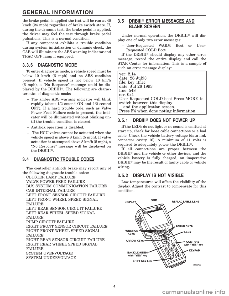
3.5.2 DISPLAY IS NOT VISIBLE
Low temperatures will affect the visibility of the
display. Adjust the contrast to compensate for this
condition.
4
GENERAL INFORMATION