2001 CHRYSLER VOYAGER display
[x] Cancel search: displayPage 1429 of 4284
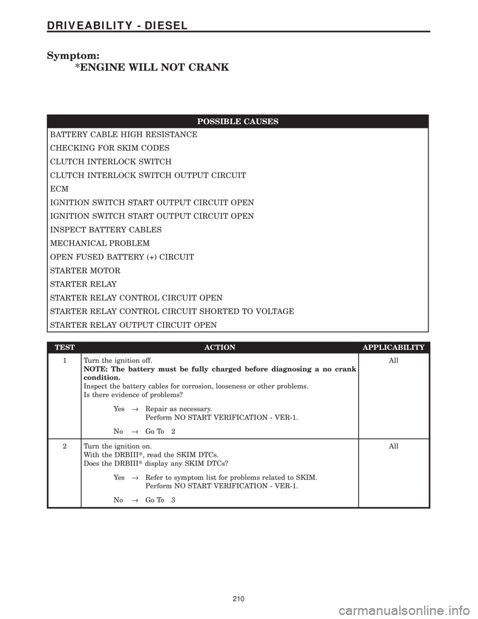
Symptom:
*ENGINE WILL NOT CRANK
POSSIBLE CAUSES
BATTERY CABLE HIGH RESISTANCE
CHECKING FOR SKIM CODES
CLUTCH INTERLOCK SWITCH
CLUTCH INTERLOCK SWITCH OUTPUT CIRCUIT
ECM
IGNITION SWITCH START OUTPUT CIRCUIT OPEN
IGNITION SWITCH START OUTPUT CIRCUIT OPEN
INSPECT BATTERY CABLES
MECHANICAL PROBLEM
OPEN FUSED BATTERY (+) CIRCUIT
STARTER MOTOR
STARTER RELAY
STARTER RELAY CONTROL CIRCUIT OPEN
STARTER RELAY CONTROL CIRCUIT SHORTED TO VOLTAGE
STARTER RELAY OUTPUT CIRCUIT OPEN
TEST ACTION APPLICABILITY
1 Turn the ignition off.
NOTE: The battery must be fully charged before diagnosing a no crank
condition.
Inspect the battery cables for corrosion, looseness or other problems.
Is there evidence of problems?All
Ye s®Repair as necessary.
Perform NO START VERIFICATION - VER-1.
No®Go To 2
2 Turn the ignition on.
With the DRBIIIt, read the SKIM DTCs.
Does the DRBIIItdisplay any SKIM DTCs?All
Ye s®Refer to symptom list for problems related to SKIM.
Perform NO START VERIFICATION - VER-1.
No®Go To 3
210
DRIVEABILITY - DIESEL
Page 1435 of 4284
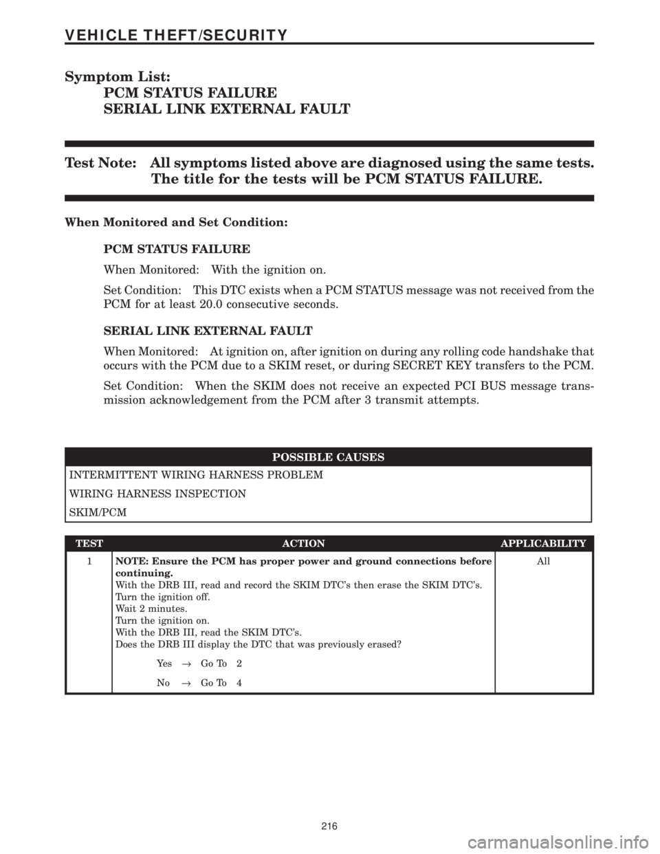
Symptom List:
PCM STATUS FAILURE
SERIAL LINK EXTERNAL FAULT
Test Note: All symptoms listed above are diagnosed using the same tests.
The title for the tests will be PCM STATUS FAILURE.
When Monitored and Set Condition:
PCM STATUS FAILURE
When Monitored: With the ignition on.
Set Condition: This DTC exists when a PCM STATUS message was not received from the
PCM for at least 20.0 consecutive seconds.
SERIAL LINK EXTERNAL FAULT
When Monitored: At ignition on, after ignition on during any rolling code handshake that
occurs with the PCM due to a SKIM reset, or during SECRET KEY transfers to the PCM.
Set Condition: When the SKIM does not receive an expected PCI BUS message trans-
mission acknowledgement from the PCM after 3 transmit attempts.
POSSIBLE CAUSES
INTERMITTENT WIRING HARNESS PROBLEM
WIRING HARNESS INSPECTION
SKIM/PCM
TEST ACTION APPLICABILITY
1NOTE: Ensure the PCM has proper power and ground connections before
continuing.
With the DRB III, read and record the SKIM DTC's then erase the SKIM DTC's.
Turn the ignition off.
Wait 2 minutes.
Turn the ignition on.
With the DRB III, read the SKIM DTC's.
Does the DRB III display the DTC that was previously erased?All
Ye s®Go To 2
No®Go To 4
216
VEHICLE THEFT/SECURITY
Page 1436 of 4284
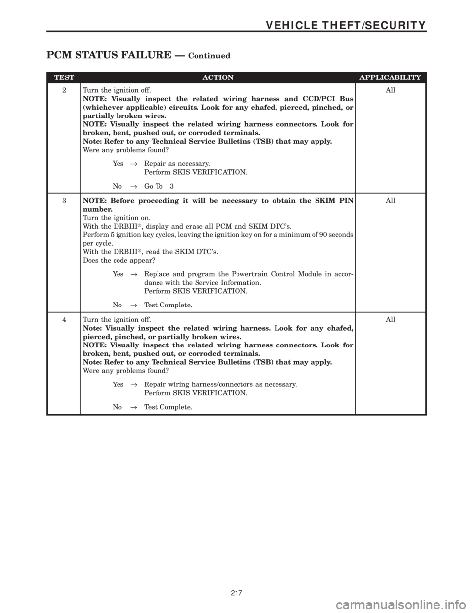
TEST ACTION APPLICABILITY
2 Turn the ignition off.
NOTE: Visually inspect the related wiring harness and CCD/PCI Bus
(whichever applicable) circuits. Look for any chafed, pierced, pinched, or
partially broken wires.
NOTE: Visually inspect the related wiring harness connectors. Look for
broken, bent, pushed out, or corroded terminals.
Note: Refer to any Technical Service Bulletins (TSB) that may apply.
Were any problems found?All
Ye s®Repair as necessary.
Perform SKIS VERIFICATION.
No®Go To 3
3NOTE: Before proceeding it will be necessary to obtain the SKIM PIN
number.
Turn the ignition on.
With the DRBIIIt, display and erase all PCM and SKIM DTC's.
Perform 5 ignition key cycles, leaving the ignition key on for a minimum of 90 seconds
per cycle.
With the DRBIIIt, read the SKIM DTC's.
Does the code appear?All
Ye s®Replace and program the Powertrain Control Module in accor-
dance with the Service Information.
Perform SKIS VERIFICATION.
No®Test Complete.
4 Turn the ignition off.
Note: Visually inspect the related wiring harness. Look for any chafed,
pierced, pinched, or partially broken wires.
NOTE: Visually inspect the related wiring harness connectors. Look for
broken, bent, pushed out, or corroded terminals.
Note: Refer to any Technical Service Bulletins (TSB) that may apply.
Were any problems found?All
Ye s®Repair wiring harness/connectors as necessary.
Perform SKIS VERIFICATION.
No®Test Complete.
217
VEHICLE THEFT/SECURITY
PCM STATUS FAILURE ÐContinued
Page 1437 of 4284
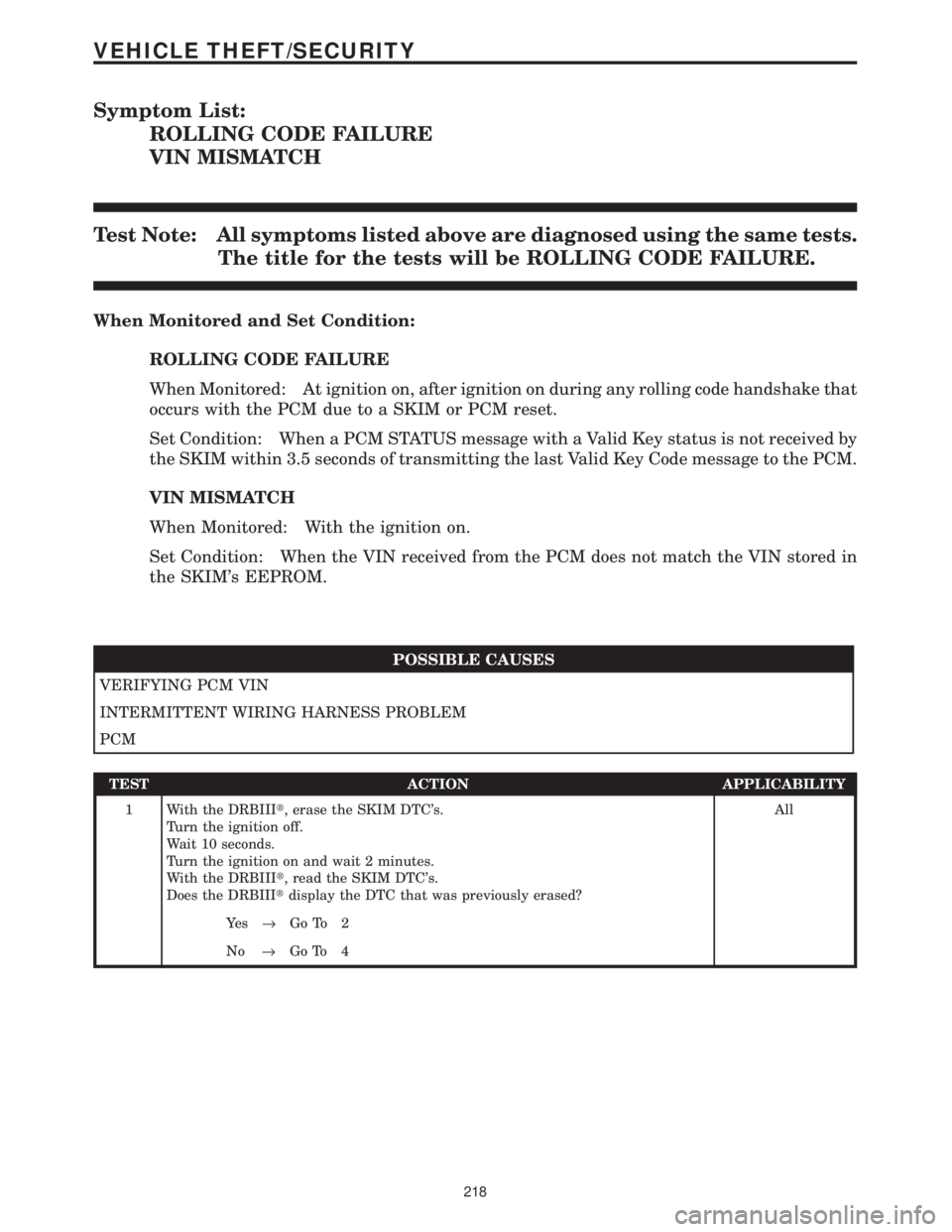
Symptom List:
ROLLING CODE FAILURE
VIN MISMATCH
Test Note: All symptoms listed above are diagnosed using the same tests.
The title for the tests will be ROLLING CODE FAILURE.
When Monitored and Set Condition:
ROLLING CODE FAILURE
When Monitored: At ignition on, after ignition on during any rolling code handshake that
occurs with the PCM due to a SKIM or PCM reset.
Set Condition: When a PCM STATUS message with a Valid Key status is not received by
the SKIM within 3.5 seconds of transmitting the last Valid Key Code message to the PCM.
VIN MISMATCH
When Monitored: With the ignition on.
Set Condition: When the VIN received from the PCM does not match the VIN stored in
the SKIM's EEPROM.
POSSIBLE CAUSES
VERIFYING PCM VIN
INTERMITTENT WIRING HARNESS PROBLEM
PCM
TEST ACTION APPLICABILITY
1 With the DRBIIIt, erase the SKIM DTC's.
Turn the ignition off.
Wait 10 seconds.
Turn the ignition on and wait 2 minutes.
With the DRBIIIt, read the SKIM DTC's.
Does the DRBIIItdisplay the DTC that was previously erased?All
Ye s®Go To 2
No®Go To 4
218
VEHICLE THEFT/SECURITY
Page 1438 of 4284
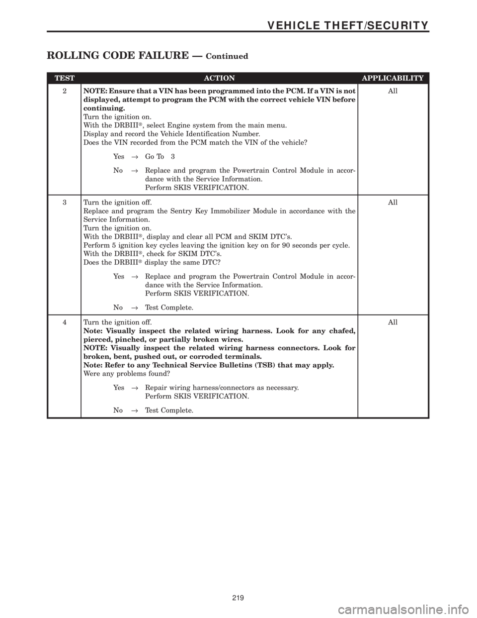
TEST ACTION APPLICABILITY
2NOTE: Ensure that a VIN has been programmed into the PCM. If a VIN is not
displayed, attempt to program the PCM with the correct vehicle VIN before
continuing.
Turn the ignition on.
With the DRBIIIt, select Engine system from the main menu.
Display and record the Vehicle Identification Number.
Does the VIN recorded from the PCM match the VIN of the vehicle?All
Ye s®Go To 3
No®Replace and program the Powertrain Control Module in accor-
dance with the Service Information.
Perform SKIS VERIFICATION.
3 Turn the ignition off.
Replace and program the Sentry Key Immobilizer Module in accordance with the
Service Information.
Turn the ignition on.
With the DRBIIIt, display and clear all PCM and SKIM DTC's.
Perform 5 ignition key cycles leaving the ignition key on for 90 seconds per cycle.
With the DRBIIIt, check for SKIM DTC's.
Does the DRBIIItdisplay the same DTC?All
Ye s®Replace and program the Powertrain Control Module in accor-
dance with the Service Information.
Perform SKIS VERIFICATION.
No®Test Complete.
4 Turn the ignition off.
Note: Visually inspect the related wiring harness. Look for any chafed,
pierced, pinched, or partially broken wires.
NOTE: Visually inspect the related wiring harness connectors. Look for
broken, bent, pushed out, or corroded terminals.
Note: Refer to any Technical Service Bulletins (TSB) that may apply.
Were any problems found?All
Ye s®Repair wiring harness/connectors as necessary.
Perform SKIS VERIFICATION.
No®Test Complete.
219
VEHICLE THEFT/SECURITY
ROLLING CODE FAILURE ÐContinued
Page 1440 of 4284
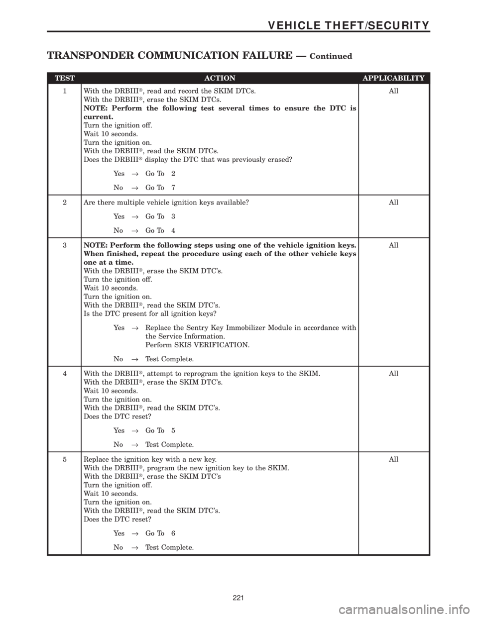
TEST ACTION APPLICABILITY
1 With the DRBIIIt, read and record the SKIM DTCs.
With the DRBIIIt, erase the SKIM DTCs.
NOTE: Perform the following test several times to ensure the DTC is
current.
Turn the ignition off.
Wait 10 seconds.
Turn the ignition on.
With the DRBIIIt, read the SKIM DTCs.
Does the DRBIIItdisplay the DTC that was previously erased?All
Ye s®Go To 2
No®Go To 7
2 Are there multiple vehicle ignition keys available? All
Ye s®Go To 3
No®Go To 4
3NOTE: Perform the following steps using one of the vehicle ignition keys.
When finished, repeat the procedure using each of the other vehicle keys
one at a time.
With the DRBIIIt, erase the SKIM DTC's.
Turn the ignition off.
Wait 10 seconds.
Turn the ignition on.
With the DRBIIIt, read the SKIM DTC's.
Is the DTC present for all ignition keys?All
Ye s®Replace the Sentry Key Immobilizer Module in accordance with
the Service Information.
Perform SKIS VERIFICATION.
No®Test Complete.
4 With the DRBIIIt, attempt to reprogram the ignition keys to the SKIM.
With the DRBIIIt, erase the SKIM DTC's.
Wait 10 seconds.
Turn the ignition on.
With the DRBIIIt, read the SKIM DTC's.
Does the DTC reset?All
Ye s®Go To 5
No®Test Complete.
5 Replace the ignition key with a new key.
With the DRBIIIt, program the new ignition key to the SKIM.
With the DRBIIIt, erase the SKIM DTC's
Turn the ignition off.
Wait 10 seconds.
Turn the ignition on.
With the DRBIIIt, read the SKIM DTC's.
Does the DTC reset?All
Ye s®Go To 6
No®Test Complete.
221
VEHICLE THEFT/SECURITY
TRANSPONDER COMMUNICATION FAILURE ÐContinued
Page 1443 of 4284
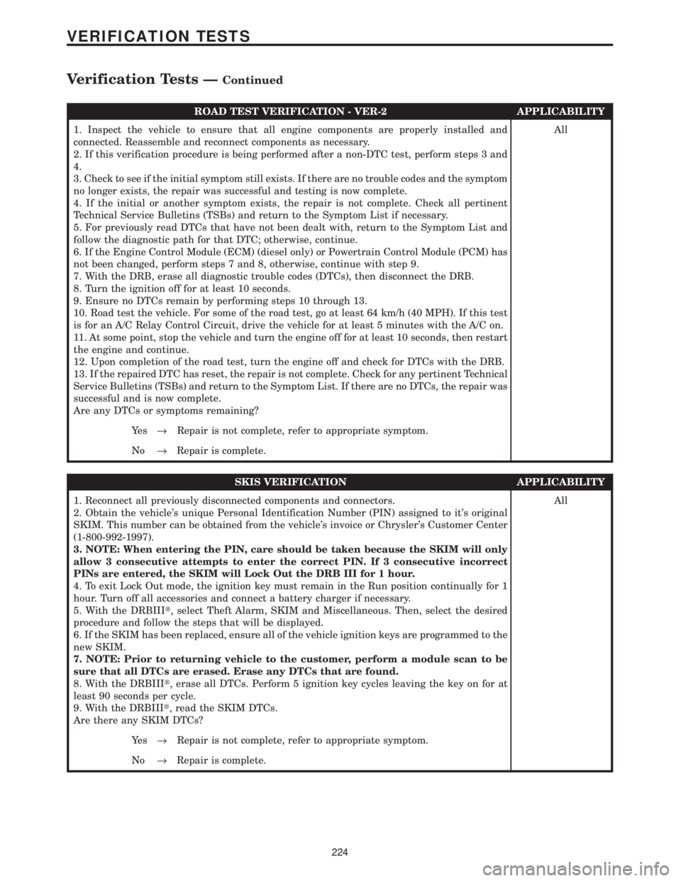
ROAD TEST VERIFICATION - VER-2 APPLICABILITY
1. Inspect the vehicle to ensure that all engine components are properly installed and
connected. Reassemble and reconnect components as necessary.
2. If this verification procedure is being performed after a non-DTC test, perform steps 3 and
4.
3. Check to see if the initial symptom still exists. If there are no trouble codes and the symptom
no longer exists, the repair was successful and testing is now complete.
4. If the initial or another symptom exists, the repair is not complete. Check all pertinent
Technical Service Bulletins (TSBs) and return to the Symptom List if necessary.
5. For previously read DTCs that have not been dealt with, return to the Symptom List and
follow the diagnostic path for that DTC; otherwise, continue.
6. If the Engine Control Module (ECM) (diesel only) or Powertrain Control Module (PCM) has
not been changed, perform steps 7 and 8, otherwise, continue with step 9.
7. With the DRB, erase all diagnostic trouble codes (DTCs), then disconnect the DRB.
8. Turn the ignition off for at least 10 seconds.
9. Ensure no DTCs remain by performing steps 10 through 13.
10. Road test the vehicle. For some of the road test, go at least 64 km/h (40 MPH). If this test
is for an A/C Relay Control Circuit, drive the vehicle for at least 5 minutes with the A/C on.
11. At some point, stop the vehicle and turn the engine off for at least 10 seconds, then restart
the engine and continue.
12. Upon completion of the road test, turn the engine off and check for DTCs with the DRB.
13. If the repaired DTC has reset, the repair is not complete. Check for any pertinent Technical
Service Bulletins (TSBs) and return to the Symptom List. If there are no DTCs, the repair was
successful and is now complete.
Are any DTCs or symptoms remaining?All
Ye s®Repair is not complete, refer to appropriate symptom.
No®Repair is complete.
SKIS VERIFICATION APPLICABILITY
1. Reconnect all previously disconnected components and connectors.
2. Obtain the vehicle's unique Personal Identification Number (PIN) assigned to it's original
SKIM. This number can be obtained from the vehicle's invoice or Chrysler's Customer Center
(1-800-992-1997).
3. NOTE: When entering the PIN, care should be taken because the SKIM will only
allow 3 consecutive attempts to enter the correct PIN. If 3 consecutive incorrect
PINs are entered, the SKIM will Lock Out the DRB III for 1 hour.
4. To exit Lock Out mode, the ignition key must remain in the Run position continually for 1
hour. Turn off all accessories and connect a battery charger if necessary.
5. With the DRBIIIt, select Theft Alarm, SKIM and Miscellaneous. Then, select the desired
procedure and follow the steps that will be displayed.
6. If the SKIM has been replaced, ensure all of the vehicle ignition keys are programmed to the
new SKIM.
7. NOTE: Prior to returning vehicle to the customer, perform a module scan to be
sure that all DTCs are erased. Erase any DTCs that are found.
8. With the DRBIIIt, erase all DTCs. Perform 5 ignition key cycles leaving the key on for at
least 90 seconds per cycle.
9. With the DRBIIIt, read the SKIM DTCs.
Are there any SKIM DTCs?All
Ye s®Repair is not complete, refer to appropriate symptom.
No®Repair is complete.
224
VERIFICATION TESTS
Verification Tests ÐContinued
Page 1472 of 4284
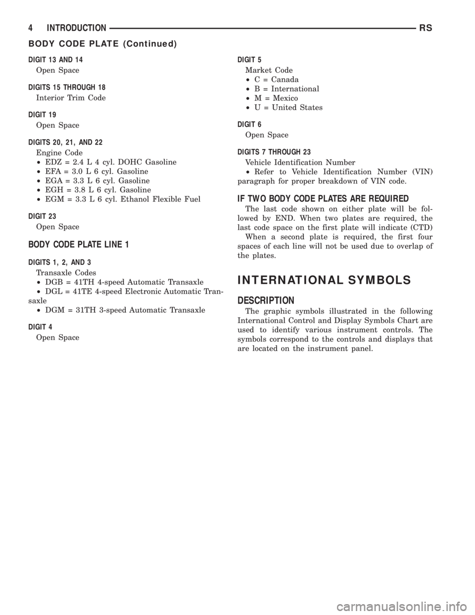
DIGIT 13 AND 14
Open Space
DIGITS 15 THROUGH 18
Interior Trim Code
DIGIT 19
Open Space
DIGITS 20, 21, AND 22
Engine Code
²EDZ = 2.4 L 4 cyl. DOHC Gasoline
²EFA = 3.0 L 6 cyl. Gasoline
²EGA = 3.3 L 6 cyl. Gasoline
²EGH = 3.8 L 6 cyl. Gasoline
²EGM = 3.3 L 6 cyl. Ethanol Flexible Fuel
DIGIT 23
Open Space
BODY CODE PLATE LINE 1
DIGITS 1, 2, AND 3
Transaxle Codes
²DGB = 41TH 4-speed Automatic Transaxle
²DGL = 41TE 4-speed Electronic Automatic Tran-
saxle
²DGM = 31TH 3-speed Automatic Transaxle
DIGIT 4
Open SpaceDIGIT 5
Market Code
²C = Canada
²B = International
²M = Mexico
²U = United States
DIGIT 6
Open Space
DIGITS 7 THROUGH 23
Vehicle Identification Number
²Refer to Vehicle Identification Number (VIN)
paragraph for proper breakdown of VIN code.
IF TWO BODY CODE PLATES ARE REQUIRED
The last code shown on either plate will be fol-
lowed by END. When two plates are required, the
last code space on the first plate will indicate (CTD)
When a second plate is required, the first four
spaces of each line will not be used due to overlap of
the plates.
INTERNATIONAL SYMBOLS
DESCRIPTION
The graphic symbols illustrated in the following
International Control and Display Symbols Chart are
used to identify various instrument controls. The
symbols correspond to the controls and displays that
are located on the instrument panel.
4 INTRODUCTIONRS
BODY CODE PLATE (Continued)