2001 CHRYSLER VOYAGER center console
[x] Cancel search: center consolePage 1978 of 4284
OPERATION
The Compass Mini-Trip Computer (CMTC), Com-
pass Temperature (CT) module in the overhead con-
sole has buttons used to select various functions. The
CMTC, CT selector buttons will not operate until the
ignition is in the RUN position.
When the ignition switch is first turned to the
RUN position the CMTC, CT display;
²Blanks momentarily
²
All segments of the VFD will light for one second
²Blanks momentarily
²Returns to the last mode setting selected before
the ignition was last switched OFF.
DIAGNOSIS & TESTING - COMPASS MINI-TRIP
COMPUTER
Compass Mini-Trip Computer (CMTC) and Com-
pass Temperature (CT) data is obtained from the
Body Control Module (BCM) on the J1850 Data Bus
circuit. The CMTC and CT will display dashes (- -)
for any of the screens it did not receive the bus mes-
sages. The label corresponding to the missing infor-
mation will be lit. If no compass mini-trip computer
data is displayed, check the J1850 Data Bus circuit
communications and the BCM. If the brightness level
is improper check the J1850 Data Bus circuit.
The DRB IIItis recommended for checking the
J1850 Data Bus circuit and the BCM. Perform the
CMTC, CT self diagnosis before replacing the CMTC
or CT module.
REMOVAL
(1) Disconnect and isolate the battery negative
cable.
(2) Remove overhead console. Refer to Overhead
Console Removal and Installation in this section(Re-
fer to 8 - ELECTRICAL/OVERHEAD CONSOLE -
REMOVAL) .
(3) Remove the screws holding Compass Mini-Trip
Computer module in the overhead console.
(4) Remove CMTC module from console assembly.
INSTALLATION
(1) Position the compass mini-trip computer mod-
ule in the overhead console.
(2) Install the ten screws holding the compass
mini-trip computer module in the overhead console.
(3) Install the overhead console. Refer to Overhead
Console Removal and Installation in this section.
(4) Connect the battery negative cable.
NOTE: If a new module has been installed, the com-
pass will have to be calibrated and the variance set.
Refer to Compass Variation Adjustment and Com-
pass Calibration in the Service Procedures section
of this group for the procedures.
UNIVERSAL TRANSMITTER
DESCRIPTION
On some RS models a Homelinkttransceiver is
standard factory-installed equipment. The Homelinkt
transceiver is integral to the Electronic Vehicle Infor-
mation Center (EVIC) and the Compass Mini-Trip
Computer (CMTC), which is located in the overhead
console. The only visible component of the Homelinkt
are the three transmitter push buttons centered
between the modules push buttons located just rear-
ward of the display screen in the overhead console.
The three Homelinkttransmitter push buttons are
identified with one, two or three light indicators so
that they be easily identified by sight or by feel.
Each of the three Homelinkttransmitter push but-
tons controls an independent radio transmitter chan-
nel. Each of these three channels can be trained to
transmit a different radio frequency signal for the
remote operation of garage door openers, motorized
gate openers, home or office lighting, security sys-
tems or just about any other device that can be
equipped with a radio receiver in the 286 to 399
MegaHertz (MHz) frequency range for remote opera-
tion. The Homelinktis capable of operating systems
using either rolling code or non-rolling code technol-
ogy.
The electronics module displays messages and a
small house-shaped icon with one, two or three dots
corresponding to the three transmitter buttons to
indicate the status of the Homelinkt. The EVIC mes-
sages are:
²Cleared Channels- Indicates that all of the
transmitter codes stored in the Homelinkthave been
successfully cleared.
²Training- Indicates that the Homelinktis in
its transmitter learning mode.
²Trained- Indicates that the Homelinkthas
successfully acquired a new transmitter code.
²Transmit- Indicates that a trained Homelinkt
transmitter button has been depressed and that the
Homelinktis transmitting.
The Homelinktcannot be repaired, and is avail-
able for service only as a unit with the EVIC or
CMTC modules. If any of these components is faulty
or damaged, the complete EVIC or CMTC module
must be replaced.
OPERATION
The Homelinktoperates on a non-switched source
of battery current so the unit will remain functional,
regardless of the ignition switch position. For more
information on the features, programming procedures
and operation of the Homelinkt, see the owner's
manual in the vehicle glove box.
8M - 10 OVERHEAD CONSOLERS
COMPASS/MINI-TRIP COMPUTER (Continued)
Page 1979 of 4284
DIAGNOSIS & TESTING - HOMELINKT
If the Homelinktis inoperative, but the Electronic
Vehicle Information Center (EVIC) or Compass Mini-
Trip Computer is operating normally, see the owner's
manual in the vehicle glove box for instructions on
training the Homelinkt. Retrain the Homelinktwith
a known good transmitter as instructed in the own-
er's manual and test the Homelinktoperation again.
If the unit is still inoperative, replace the faulty
Homelinktand EVIC/CMTC module as a unit. If
both the Homelinktand the EVIC/CMTC module are
inoperative, refer toOverhead Console Diagnosis
and Testingearlier in this group for further diagno-
sis. For complete circuit diagrams, refer toOver-
head Consolein Wiring Diagrams.
AMBIENT TEMP SENSOR
DESCRIPTION
Ambient air temperature is monitored by the over-
head console through ambient temperature messages
received from the Front Control Module (FCM) over
the Programmable Communications Interface (PCI)
J1850 data bus circuit. The FCM receives a hard
wired input from the ambient temperature sensor.
The ambient temperature sensor is a variable resis-
tor mounted to a bracket that is secured with a screw
to the right side of the headlamp mounting module
grille opening, behind the radiator grille and in front
of the engine compartment.
Refer toFront Control Modulein Electronic
Control Modules. For complete circuit diagrams, refer
to the appropriate wiring information. The ambient
temperature sensor cannot be adjusted or repaired
and, if faulty or damaged, it must be replaced.
OPERATION
The ambient temperature sensor is a variable
resistor that operates on a five-volt reference signal
sent to it by the Front Control Module. The resis-
tance in the sensor changes as temperature changes,
changing the temperature sensor signal circuit volt-
age to the Front Control Module. Based upon the
resistance in the sensor, the Front Control Module
senses a specific voltage on the temperature sensor
signal circuit, which it is programmed to correspond
to a specific temperature. The Front Control Module
then sends the proper ambient temperature mes-
sages to the EVIC, CMTC over the PCI J1850 data
bus.
The thermometer function is supported by the
ambient temperature sensor, a wiring circuit, the
Front Control Module, the Programmable Communi-
cations Interface (PCI) data bus, and a portion of the
Electronics module. If any portion of the ambienttemperature sensor circuit fails, the Front Control
Module will self-diagnose the circuit.
The ambient temperature sensor circuit can also be
diagnosed by referring toDiagnosis and Testing -
Ambient Temperature Sensor, and Diagnosis
and Testing - Ambient Temperature Sensor Cir-
cuit. If the temperature sensor and circuit are con-
firmed to be OK, but the temperature display is
inoperative or incorrect, refer toDiagnosis and
Testing - Overhead Consolein this group. For
complete circuit diagrams, refer to the appropriate
wiring information.
DIAGNOSIS AND TESTING - AMBIENT
TEMPERATURE SENSOR
(1) Turn the ignition switch to the Off position.
Disconnect and isolate the battery negative cable.
Disconnect the ambient temperature sensor wire har-
ness connector.
(2) Measure the resistance of the ambient temper-
ature sensor. At ±40É C (±40É F), the sensor resis-
tance is 336 kilohms. At 55É C (140É F), the sensor
resistance is 2.488 kilohms. The sensor resistance
should read between these two values. If OK, refer to
Diagnosis and Testing - Ambient Temperature
Sensor Circuitin this group. If not OK, replace the
faulty ambient temperature sensor.
DIAGNOSIS AND TESTING - AMBIENT
TEMPERATURE SENSOR CIRCUIT
(1) Turn the ignition switch to the Off position.
Disconnect and isolate the battery negative cable.
Disconnect the ambient temperature sensor wire har-
ness connector and the Front Control Module wire
harness connector.
(2) Connect a jumper wire between the two termi-
nals in the body half of the ambient temperature sen-
sor wire harness connector.
(3) Check for continuity between the sensor return
circuit and the ambient temperature sensor signal
circuit cavities of the Front Control Module wire har-
ness connector. There should be continuity. If OK, go
to Step 4. If not OK, repair the open sensor return
circuit or ambient temperature sensor signal circuit
to the ambient temperature sensor as required.
(4) Remove the jumper wire from the body half of
the ambient temperature sensor wire harness con-
nector. Check for continuity between the sensor
return circuit cavity of the Front Control Module
wire harness connector and a good ground. There
should be no continuity. If OK, go to Step 5. If not
OK, repair the shorted sensor return circuit as
required.
(5) Check for continuity between the ambient tem-
perature sensor signal circuit cavity of the Front
Control Module wire harness connector and a good
RSOVERHEAD CONSOLE8M-11
UNIVERSAL TRANSMITTER (Continued)
Page 1982 of 4284
POWER LIFTGATE SYSTEM
DESCRIPTION
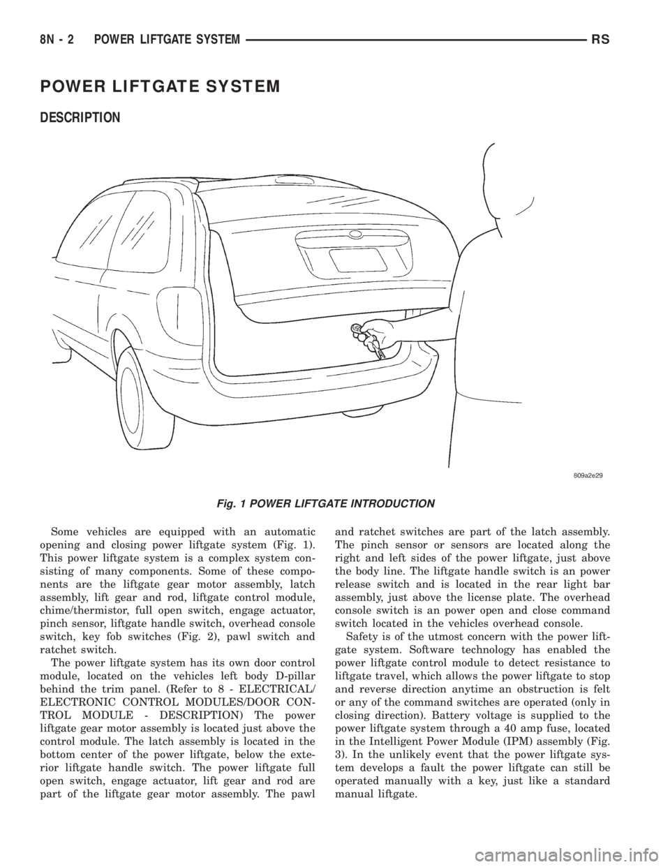
Some vehicles are equipped with an automatic
opening and closing power liftgate system (Fig. 1).
This power liftgate system is a complex system con-
sisting of many components. Some of these compo-
nents are the liftgate gear motor assembly, latch
assembly, lift gear and rod, liftgate control module,
chime/thermistor, full open switch, engage actuator,
pinch sensor, liftgate handle switch, overhead console
switch, key fob switches (Fig. 2), pawl switch and
ratchet switch.
The power liftgate system has its own door control
module, located on the vehicles left body D-pillar
behind the trim panel. (Refer to 8 - ELECTRICAL/
ELECTRONIC CONTROL MODULES/DOOR CON-
TROL MODULE - DESCRIPTION) The power
liftgate gear motor assembly is located just above the
control module. The latch assembly is located in the
bottom center of the power liftgate, below the exte-
rior liftgate handle switch. The power liftgate full
open switch, engage actuator, lift gear and rod are
part of the liftgate gear motor assembly. The pawland ratchet switches are part of the latch assembly.
The pinch sensor or sensors are located along the
right and left sides of the power liftgate, just above
the body line. The liftgate handle switch is an power
release switch and is located in the rear light bar
assembly, just above the license plate. The overhead
console switch is an power open and close command
switch located in the vehicles overhead console.
Safety is of the utmost concern with the power lift-
gate system. Software technology has enabled the
power liftgate control module to detect resistance to
liftgate travel, which allows the power liftgate to stop
and reverse direction anytime an obstruction is felt
or any of the command switches are operated (only in
closing direction). Battery voltage is supplied to the
power liftgate system through a 40 amp fuse, located
in the Intelligent Power Module (IPM) assembly (Fig.
3). In the unlikely event that the power liftgate sys-
tem develops a fault the power liftgate can still be
operated manually with a key, just like a standard
manual liftgate.
Fig. 1 POWER LIFTGATE INTRODUCTION
8N - 2 POWER LIFTGATE SYSTEMRS
Page 1999 of 4284
POWER SLIDING DOOR SYSTEM
TABLE OF CONTENTS
page page
POWER SLIDING DOOR SYSTEM
DESCRIPTION...........................19
OPERATION.............................21
DIAGNOSIS AND TESTING.................22
DIAGNOSIS AND TESTING - POWER
SLIDING DOOR SYSTEM.................22
STANDARD PROCEDURE..................28
WELLNUT REPLACEMENT...............28
POWER DOOR LEARN CYCLE............28
SLIDING DOOR ADJUSTMENT............28
LATCH
DESCRIPTION...........................29
OPERATION.............................29
REMOVAL..............................29
INSTALLATION...........................30
SLIDING DOOR MOTOR
DESCRIPTION...........................30
OPERATION.............................30
REMOVAL..............................31
INSTALLATION...........................31
FULL OPEN SWITCH
DESCRIPTION...........................31
OPERATION.............................31
LEFT B-PILLAR SWITCH
DESCRIPTION...........................32
OPERATION.............................32
REMOVAL..............................32INSTALLATION...........................32
RIGHT B-PILLAR SWITCH
DESCRIPTION...........................32
OPERATION.............................32
REMOVAL..............................32
INSTALLATION...........................32
LOWER DRIVE UNIT
DESCRIPTION...........................33
OPERATION.............................33
REMOVAL..............................33
INSTALLATION...........................34
LOWER DRIVE UNIT TRACK & RACK
DESCRIPTION...........................34
OPERATION.............................34
REMOVAL..............................34
INSTALLATION...........................35
WIRING HARNESS
DESCRIPTION...........................35
OPERATION.............................35
REMOVAL..............................35
INSTALLATION...........................36
FLEX DRIVE
DESCRIPTION...........................36
OPERATION.............................36
REMOVAL..............................37
INSTALLATION...........................38
POWER SLIDING DOOR
SYSTEM
DESCRIPTION
Some vehicles are equipped with a power opening
and closing sliding door system (Fig. 1). Depending
on how the vehicle is ordered it may be equipped
with only a right side power door or right and left
side power doors. This power sliding door system is a
complex system consisting of many components.
Some of these components are the door motor, latch
assembly, sliding door control module, lower drive
unit, flex drive assembly, wire harness and track,
lower drive unit track and rack assembly, full open
switch, B-pillar switch, overhead console switch, key
fob switches (Fig. 2), pawl switch, ratchet switch and
child lockout and handle switches.
Each power side door has its own door control mod-
ule, located in the center of the door behind the door
trim panel. (Refer to 8 - ELECTRICAL/ELEC-TRONIC CONTROL MODULES/DOOR CONTROL
MODULE - DESCRIPTION) The power side door
motor is located in the front portion of the door, on
the inner door panel sheet metal. The latch assembly
is located in the rear of the power side door, near the
body line. The lower drive unit is attached to the
lower door hinge. The flex drive assembly connects
the door motor to the lower drive unit. The wire har-
ness and track and the lower drive unit track are vis-
ible with the door open in the lower door sill area.
The power side door full open switch is located under
the lower drive unit and is part of the hold open
latch assembly. The pawl, ratchet, handle and child
lockout switches are all located on the power side
door latch assembly. The B-pillar switch, as it will be
referred to, is an open and close command switch
located on the vehicles interior body side B-pillar
trim. The overhead console switch, is an open and
close command switch located in the vehicle's over-
head console. More detailed information can be found
on these components later in this section.
RSPOWER SLIDING DOOR SYSTEM8N-19
Page 2030 of 4284
A eight-way power seat is standard on highline
models and optional on others. This option includes a
six-way adjustable seat cushion track and a two-way
power seat back.
The eight-way power seat is also available with the
heated seat and memory seat system that automati-
cally positions the power seat for two different driv-
ers. Refer toHeated Seat Systemfor more
information on the heated seat option. Refer toMem-
ory Systemin the Memory System section of this
group for more information on the memory system.
The power seat system includes the following com-
ponents:
²Power seat recliner
²Power seat switch
²Power seat track.
The power seat system with memory and heated
seat options includes the following components:
²Power seat recliner
²Power seat switch
²Power seat track.
²Memory Heated Seat Module (MHSM)
²Memory set switch
²Heated seat switch
²Electronic Vehicle Information Center (EVIC)
²Programmable Communications Interface (PCI)
data bus network
Refer to Wiring Diagrams for complete circuit dia-
grams. Following are general descriptions and opera-
tions for the major components in the power seat
system and memory seat system.
DESCRIPTION - MEMORY SEAT SYSTEM
An electronic memory and heated seat system is
available on some models. The memory system is
able to store and recall the driver side power seat
positions (including the power recliner position), and
both outside power mirror positions for two drivers.
For vehicles with a radio and heated / memory seat
system connected to the Programmable Communica-
tions Interface (PCI) data bus network, the memory
system is also able to store and recall radio station
presets for two drivers. The memory system also will
store and recall the last station listened to for each
driver, even if it is not one of the preset stations.
The memory system will automatically return to
all of these settings when the corresponding num-
bered and button of the memory switch on the driver
side seat side shield is depressed, or when the doors
are unlocked using the Remote Keyless Entry (RKE)
transmitter. A customer programmable feature of the
memory system allows the RKE recall of memory fea-
tures to be disabled in cases where there are more
than two drivers of the vehicle.
A Memory Heated Seat Module (MHSM) is used on
some models to control and integrate the many elec-tronic functions and features included in the memory
/ heated seat system.
The memory system includes the following compo-
nents:
²Heated seat switch
²Memory heated seat module (MHSM)
²Memory switch
²Position potentiometers on both outside power
mirrors
²Position potentiometers on the driver side power
seat track and power seat recliner motors.
²Radio receiver (if PCI data bus capable).
Certain functions and features of the memory system
rely upon resources shared with other electronic mod-
ules in the vehicle over the Programmable Communica-
tions Interface (PCI) J1850 data bus network. The PCI
data bus network allows the sharing of sensor informa-
tion. This helps to reduce wire harness complexity,
internal controller hardware, and component sensor cur-
rent loads. At the same time, this system provides
increased reliability, enhanced diagnostics, and allows
the addition of many new feature capabilities. For diag-
nosis of these electronic modules or of the PCI data bus
network, the use of a DRBtscan tool and the proper
Diagnostic Procedures manual are recommended.
The other electronic modules that may affect mem-
ory system operation are as follows:
²Body Control Module (BCM)- Refer toBody
Control Modulein Electronic Control Modules for
more information.
²
Electronic Vehicle Information Center (EVIC)
- Refer toElectronic Vehicle Information Center
in Overhead Console Systems for more information.
²Powertrain Control Module (PCM)- Refer to
Powertrain Control Modulein Electronic Control
Modules for more information.
²Radio Receiver- Refer toRadio Receiverin
Audio Systems for more information.
Refer toHeated Seat Systemfor more informa-
tion on the heated seat system. Refer toRemote
Keyless Entry Systemin Power Lock Systems for
more information on the RKE system. Refer to
Power Mirrorin Power Mirrors for more informa-
tion on the mirror position potentiometers. Refer to
Power Seat TrackandPower Seat Reclinerin
the Power Seat System section of this group for more
information on the driver side power seat position
potentiometers.
Refer toPower Seatin the Contents of Wiring
Diagrams for complete circuit diagrams. Following
are general descriptions of the remaining major com-
ponents in the factory-installed memory system.
OPERATION - POWER SEAT SYSTEM
The power seat system allows the driver and/or
front passenger seating positions to be adjusted elec-
8N - 50 POWER SEATSRS
POWER SEATS (Continued)
Page 2031 of 4284
trically and independently using the separate power
seat switches found on the outboard seat cushion
side shield of each front seat. See the owner's manual
in the vehicle glove box for more information on the
features, use and operation of the power seat system.
OPERATION - MEMORY SYSTEM
The Memory Seat/Mirror Module (MSMM) will
drive a maximum of 2 motors at a time in a given
direction. If conflicting directions are requested, the
priority for response will be as follows:
²Seat Track Rearward
²Seat Front Down
²Seat Rear Down
²Recliner Rearward
²Seat Track Forward
²Seat Front Up
²Seat Rear Up
²Recliner Forward
The inputs from these switches to the MSMM is a
current limited battery source fed by the MSMM.
This protects the MSMM printed circuit board traces
from acting as fuses. All of these switch contact
inputs to the MSMM are normally closed to ground,
except when actuated.
Soft stops are incorporated to prevent the motor
from being driven into a stall. Should the seat have
restricted travel, refer to Resetting Soft Stops in this
section.
See the owner's manual in the vehicle glove box for
more information on the features, use and operation
of the memory system. For diagnosis of the MSM, the
PCI data bus, or the other electronic modules on the
PCI data bus that provide inputs and outputs for the
memory system, the use of a DRBtscan tool and the
proper Diagnostic Procedures manual are recom-
mended.
ELECTRONIC VEHICLE INFORMATION CENTER
The Electronic Vehicle Information Center (EVIC)
serves as the user interface for the memory system.
It displays memory system status messages and pro-
vides the user with the means for enabling and dis-
abling the many customer programmable features
available on the vehicle, including those for the mem-
ory system.
See the owner's manual in the vehicle glove box for
more information on the features, use and operation
of the EVIC. Refer toElectronic Vehicle Informa-
tion Centerin Overhead Console Systems for more
information on the EVIC.
DIAGNOSIS AND TESTING - POWER SEAT
SYSTEM
Following are tests that will help to diagnose the
hard wired components and circuits of the power seatsystem. However, if the vehicle is also equipped with
the optional memory system, these tests may not
prove conclusive in the diagnosis of the driver side
power seat. In order to obtain conclusive testing of
the driver side power seat with the memory system
option, the Programmable Communications Interface
(PCI) data bus network and all of the electronic mod-
ules that provide inputs to, or receive outputs from
the memory system components must be checked.
The most reliable, efficient, and accurate means to
diagnose the driver side power seat with the memory
system option requires the use of a DRBtscan tool
and the proper Diagnostic Procedures manual. The
DRBtscan tool can provide confirmation that the
PCI data bus is functional, that all of the electronic
modules are sending and receiving the proper mes-
sages on the PCI data bus, and that the memory sys-
tem is receiving the proper hard wired inputs and
relaying the proper hard wired outputs to perform its
driver side power seat functions.
WARNING: SOME VEHICLES ARE EQUIPPED WITH
SEATBACK MOUNTED AIRBAGS (Fig. 1). BEFORE
ATTEMPTING TO DIAGNOSE OR SERVICE ANY
SEAT OR POWER SEAT SYSTEM COMPONENT
YOU MUST FIRST DISCONNECT AND ISOLATE THE
BATTERY NEGATIVE CABLE. THEN WAIT TWO MIN-
UTES FOR THE SYSTEM CAPACITOR TO DIS-
CHARGE BEFORE FURTHER SYSTEM SERVICE.
THIS IS THE ONLY SURE WAY TO DISABLE THE
AIRBAG SYSTEM. FAILURE TO DO SO COULD
RESULT IN ACCIDENTAL AIRBAG DEPLOYMENT
AND POSSIBLE PERSONAL INJURY.
Before any testing of the power seat system is
attempted, the battery should be fully-charged and
all of the power seat system wire harness connections
and pins cleaned and tightened to ensure proper cir-
cuit continuity and ground paths. For complete cir-
cuit diagrams, refer toPower Seatin Wiring
Diagrams.
With the dome lamp on, apply the power seat
switch in the direction of the failure. If the dome
lamp dims, the seat may be jamming. Check under
and behind the seat for binding or obstructions. If
the dome lamp does not dim, proceed with testing of
the individual components and circuits.
DIAGNOSIS AND TESTING - MEMORY SYSTEM
CHECK AND RESET SOFT STOPS
To check and reset the power memory seat soft
stops, use the power seat control switches to move
the seat in one direction to the end of travel, allow a
couple of seconds before re-energizing the seat in the
same direction until it stops and for three additional
seconds after it stops. (The amount the seat moved
RSPOWER SEATS8N-51
POWER SEATS (Continued)
Page 2085 of 4284
WIRING
TABLE OF CONTENTS
page page
WIRING DIAGRAM INFORMATION...... 8Wa-01-1
COMPONENT INDEX................. 8Wa-02-1
POWER DISTRIBUTION.............. 8Wa-10-1
GROUND DISTRIBUTION............. 8Wa-15-1
BUS COMMUNICATIONS............. 8Wa-18-1
CHARGING SYSTEM................. 8Wa-20-1
STARTING SYSTEM................. 8Wa-21-1
FUEL/IGNITION SYSTEM............. 8Wa-30-1
TRANSMISSION CONTROL SYSTEM.... 8Wa-31-1
VEHICLE SPEED CONTROL........... 8Wa-33-1
ANTILOCK BRAKES.................. 8Wa-35-1
VEHICLE THEFT SECURITY SYSTEM.... 8Wa-39-1
INSTRUMENT CLUSTER.............. 8Wa-40-1
HORN/CIGAR LIGHTER/POWER OUTLET . 8Wa-41-1
AIR CONDITIONING-HEATER.......... 8Wa-42-1
AIRBAG SYSTEM................... 8Wa-43-1
INTERIOR LIGHTING................. 8Wa-44-1
BODY CONTROL MODULE............ 8Wa-45-1MESSAGE CENTER.................. 8Wa-46-1
AUDIO SYSTEM.................... 8Wa-47-1
REAR WINDOW DEFOGGER........... 8Wa-48-1
OVERHEAD CONSOLE................ 8Wa-49-1
FRONT LIGHTING................... 8Wa-50-1
REAR LIGHTING.................... 8Wa-51-1
TURN SIGNALS..................... 8Wa-52-1
WIPERS........................... 8Wa-53-1
TRAILER TOW...................... 8Wa-54-1
POWER WINDOWS.................. 8Wa-60-1
POWER DOOR LOCKS............... 8Wa-61-1
POWER MIRRORS.................. 8Wa-62-1
POWER SEATS..................... 8Wa-63-1
SPLICE INFORMATION............... 8Wa-70-1
CONNECTOR PIN-OUTS.............. 8Wa-80-1
CONNECTOR/GROUND LOCATIONS BUX . 8Wa-90-1
SPLICE LOCATIONS BUX............. 8Wa-95-1 RGWIRING
8Wa-1
Page 2099 of 4284
8W-02 COMPONENT INDEX
Component Page
A/C Compressor Clutch Relay........... 8Wa-42
A/C Compressor Clutch................ 8Wa-42
A/C-Heater Control................... 8Wa-42
A/C Pressure Sensor.................. 8Wa-42
Accelerator Pedal Position Sensor........ 8Wa-30
Accessory Relay...................... 8Wa-10
Airbags............................. 8Wa-43
Ambient Temp Sensor................. 8Wa-49
Antenna............................ 8Wa-47
ATC Remote Sensor................... 8Wa-42
Auto Shut Down Relay................. 8Wa-30
Auto Temp Control.................... 8Wa-42
Automatic Day/Night Mirror............ 8Wa-49
Autostick Switch..................... 8Wa-31
Back-Up Lamp Switch................. 8Wa-51
Battery Temperature Sensor............ 8Wa-20
Battery............................. 8Wa-20
Blend Door Actuators.................. 8Wa-42
Blower Motor Resistor................. 8Wa-42
Body Control Module.................. 8Wa-45
Boost Pressure Sensor................. 8Wa-30
B-Pillar Switches..................... 8Wa-61
Brake Fluid Level Switch............... 8Wa-40
Brake Lamp Switch................... 8Wa-51
Brake Transmission Shift Interlock
Solenoid.......................... 8Wa-31
Cabin Heater Assist................... 8Wa-30
Camshaft Position Sensor.............. 8Wa-30
CD Changer......................... 8Wa-47
Center High Mounted Stop Lamp........ 8Wa-51
Cinch/Release Motors.................. 8Wa-61
Clockspring................. 8Wa-33, 41, 43, 47
Clutch Pedal Interlock Switch Jumper..... 8Wa-10
Clutch Pedal Interlock Switch........... 8Wa-10
Clutch Pedal Upstop Switch............. 8Wa-30
Combination Relays................... 8Wa-54
Controller Antilock Brake.............. 8Wa-35
Crank Case Ventilation Heater.......... 8Wa-30
Crankshaft Position Sensor............. 8Wa-30
Cylinder Lock Switches................ 8Wa-39
Data Link Connector.................. 8Wa-18
Defogger Relay....................... 8Wa-48
Diagnostic Junction Port............... 8Wa-18
Dome Lamps........................ 8Wa-44
Door Ajar Switches.................... 8Wa-39
Door Courtesy Lamps.................. 8Wa-44
Door Lock Motor/Ajar Switches.......... 8Wa-61
Door Lock Switches................... 8Wa-61
Dosing Pump........................ 8Wa-30
Driver Heated Seat Module............. 8Wa-63
ECM/PCM Relay..................... 8Wa-30
EGR Solenoid........................ 8Wa-30Component Page
Electric Wiper De-Icer................. 8Wa-48
Engine Control Module................ 8Wa-30
Engine Coolant Temp Sensor............ 8Wa-30
Engine Oil Pressure Sensor............. 8Wa-30
Engine Oil Pressure Switch............. 8Wa-30
Engine Oil Temperature Sensor.......... 8Wa-30
EVAP/Purge Solenoid.................. 8Wa-30
Evaporator Temperature Sensor......... 8Wa-42
Floor Console Lamp................... 8Wa-44
Floor Console Power Outlet............. 8Wa-41
Fog Lamps.......................... 8Wa-50
Front Blower Module.................. 8Wa-42
Front Blower Motor Relay.............. 8Wa-42
Front Blower Motor................... 8Wa-42
Front Cigar Lighter................... 8Wa-41
Front Control Module.................. 8Wa-10
Front Fog Lamp Relay................. 8Wa-50
Front Intrusion Sensor................. 8Wa-39
Front Reading Lamps/Switch............ 8Wa-44
Front Washer Pump Motor.............. 8Wa-53
Front Wiper Hi/Low Relay.............. 8Wa-53
Front Wiper On/Off Relay.............. 8Wa-53
Fuel Heater Relay.................... 8Wa-10
Fuel Heater......................... 8Wa-30
Fuel Injectors........................ 8Wa-30
Fuel Pressure Sensor.................. 8Wa-30
Fuel Pressure Solenoid................. 8Wa-30
Fuel Pump Module.................... 8Wa-30
Fuel Pump Relay..................... 8Wa-30
Full Open Switches................... 8Wa-61
Fuselink............................ 8Wa-10
Fuses (IPM)......................... 8Wa-10
Generator........................... 8Wa-20
Glove Box Lamp...................... 8Wa-44
Glow Plug Relay...................... 8Wa-30
Glow Plugs.......................... 8Wa-30
Grounds............................ 8Wa-15
Halo Lamp.......................... 8Wa-44
Headlamp Leveling Motors............. 8Wa-50
Headlamp Switch..................... 8Wa-50
Headlamp Washer Pump Motor.......... 8Wa-53
Headlamp Washer Relay............... 8Wa-53
Headlamps.......................... 8Wa-50
Heated Seat Backs.................... 8Wa-63
Heated Seat Cushions................. 8Wa-63
High Beam Lamps.................... 8Wa-50
Hood Ajar Switch..................... 8Wa-39
Horn Relay.......................... 8Wa-41
Horn Switch......................... 8Wa-41
Horns.............................. 8Wa-41
Idle Air Control Motor................. 8Wa-30
Ignition Coil......................... 8Wa-30
RG8W-02 COMPONENT INDEX8Wa-02-1