2001 CHRYSLER VOYAGER ESP
[x] Cancel search: ESPPage 1845 of 4284
²Fuel system monitor
²EGR monitor
²Purge system monitor
²All inputs monitored for proper voltage range.
²All monitored components (refer to the Emission
section for On-Board Diagnostics).
The PCM compares the upstream and downstream
heated oxygen sensor inputs to measure catalytic
convertor efficiency. If the catalyst efficiency drops
below the minimum acceptable percentage, the PCM
stores a diagnostic trouble code in memory.
During certain idle conditions, the PCM may enter
a variable idle speed strategy. During variable idle
speed strategy the PCM adjusts engine speed based
on the following inputs.
²A/C sense
²Battery voltage
²Battery temperature
²Engine coolant temperature
²Engine run time
²Inlet/Intake air temperature
²Vehicle mileage
ACCELERATION MODE
This is a CLOSED LOOP mode. The PCM recog-
nizes an abrupt increase in Throttle Position sensor
output voltage or MAP sensor output voltage as a
demand for increased engine output and vehicle
acceleration. The PCM increases injector pulse width
in response to increased fuel demand.
DECELERATION MODE
This is a CLOSED LOOP mode. During decelera-
tion the following inputs are received by the PCM:
²A/C sense
²Battery voltage
²Inlet/Intake air temperature
²Engine coolant temperature
²Crankshaft position (engine speed)
²Exhaust gas oxygen content (upstream heated
oxygen sensor)
²Knock sensor
²Manifold absolute pressure
²Throttle position
²IAC motor control changes in response to MAP
sensor feedback
The PCM may receive a closed throttle input from
the Throttle Position Sensor (TPS) when it senses an
abrupt decrease in manifold pressure. This indicates
a hard deceleration. In response, the PCM may
momentarily turn off the injectors. This helps
improve fuel economy, emissions and engine braking.
WIDE-OPEN-THROTTLE MODE
This is an OPEN LOOP mode. During wide-open-
throttle operation, the following inputs are used by
the PCM:
²Inlet/Intake air temperature
²Engine coolant temperature
²Engine speed
²Knock sensor
²Manifold absolute pressure
²Throttle position
When the PCM senses a wide-open-throttle condi-
tion through the Throttle Position Sensor (TPS) it de-
energizes the A/C compressor clutch relay. This
disables the air conditioning system.
The PCM does not monitor the heated oxygen sen-
sor inputs during wide-open-throttle operation except
for downstream heated oxygen sensor and both
shorted diagnostics. The PCM adjusts injector pulse
width to supply a predetermined amount of addi-
tional fuel.
IGNITION SWITCH OFF MODE
When the operator turns the ignition switch to the
OFF position, the following occurs:
²All outputs are turned off, unless 02 Heater
Monitor test is being run. Refer to the Emission sec-
tion for On-Board Diagnostics.
²No inputs are monitored except for the heated
oxygen sensors. The PCM monitors the heating ele-
ments in the oxygen sensors and then shuts down.
STANDARD PROCEDURES - OBTAINING
DIAGNOSTIC TROUBLE CODES
BULB CHECK
Each time the ignition key is turned to the ON
position, the malfunction indicator (check engine)
lamp on the instrument panel should illuminate for
approximately 2 seconds then go out. This is done for
a bulb check. When the key is in the power on, but
engine off position, the MIL will remain illuminated
for regulatory purposes.
OBTAINING DTC'S USING DRB SCAN TOOL
(1) Connect the DRB scan tool to the data link
(diagnostic) connector. This connector is located in
the passenger compartment; at the lower edge of
instrument panel; near the steering column.
(2) Turn the ignition switch on and access the
ªRead Faultº screen.
(3) Record all the DTC's and ªfreeze frameº infor-
mation shown on the DRB scan tool.
RSELECTRONIC CONTROL MODULES8E-21
POWERTRAIN CONTROL MODULE (Continued)
Page 1847 of 4284
SKIM is properly installed on the steering column,
the antenna ring fits snugly around the circumfer-
ence of the ignition lock cylinder housing. If this ring
is not mounted properly, communication problems
may arise in the form of transponder-related faults.
For added system security, each SKIM is pro-
grammed with a unique9Secret Key9code. This code
is stored in memory and is sent over the PCI bus to
the PCM and to each key that is programmed to
work with the vehicle. The9Secret Key9code is there-
fore a common element found in all components of
the Sentry Key Immobilizer System (SKIS). In the
event that a SKIM replacement is required, the
9Secret Key9code can be restored from the PCM by
following the SKIM replacement procedure found in
the DRB IIItscan tool. Proper completion of this
task will allow the existing ignition keys to be repro-
grammed. Therefore, new keys will NOT be needed.
In the event that the original9Secret Key9code can
not be recovered, new ignition keys will be required.
The DRB IIItscan tool will alert the technician if
key replacement is necessary. Another security code,
called a PIN, is used to gain secured access to the
SKIM for service. The SKIM also stores in its mem-
ory the Vehicle Identification Number (VIN), which it
learns through a bus message from the assembly
plant tester. The SKIS scrambles the information
that is communicated between its components in
order to reduce the possibility of unauthorized SKIM
access and/or disabling.
OPERATION
When the ignition switch is moved to the RUN
position, the SKIM transmits an RF signal to the
transponder in the ignition key. The SKIM then
waits for a response RF signal from the transponder
in the key. If the response received identifies the key
as valid, the SKIM sends a9valid key9message to
the PCM over the PCI bus. If the response received
identifies the key as invalid or no response is
received from the transponder in the ignition key, the
SKIM sends an9invalid key9message to the PCM.
The PCM will enable or disable engine operation
based upon the status of the SKIM messages. It is
important to note that the default condition in the
PCM is9invalid key.9Therefore, if no response is
received by the PCM, the engine will be immobilized
after two (2) seconds of running.
The SKIM also sends indicator light status mes-
sages to the BCM to operate the light. This is the
method used to turn the light ON solid or to flash it
after the indicator light test is complete to signify a
fault in the SKIS. If the light comes ON and stays
ON solid after the indicator light test, this signifies
that the SKIM has detected a system malfunction
and/or that the SKIS has become inoperative. If theSKIM detects an invalid keyORa key-related fault
exists, the indicator light will flash following the
indicator light test. The SKIM may also request an
audible chime if the customer key programming fea-
ture is available and the procedure is being utilized.
Refer to Electrical, Vehicle Theft Security, Transpon-
der Key, Standard Procedure - Transponder Program-
ming.
REMOVAL
(1) Disconnect and isolate the battery negative
cable.
(2) Remove Lower Instrument Panel Cover. Refer
to Body, Instrument Panel, Lower Instrument Panel
Cover, Removal.
(3) Remove the steering column upper and lower
shrouds. Refer to Steering, Column, Column Shroud,
Removal.
(4) Disengage the steering column wire harness
from the Sentry Key Immobilizer Module (SKIM).
(5) Remove the one screws securing the SKIM to
the steering column.
(6) Rotate the SKIM upwards and then to the side
away from the steering column to slide the SKIM
antenna ring from around the ignition switch lock
cylinder housing.
(7) Remove the SKIM from the vehicle.
INSTALLATION
(1) Slip the SKIM antenna ring around the igni-
tion switch lock cylinder housing. Rotate the SKIM
downwards and then towards the steering column.
(2) Install the one screws securing the SKIM to
the steering column.
(3) Engage the steering column wire harness from
the Sentry Key Immobilizer Module (SKIM).
(4) Install the steering column upper and lower
shrouds. Refer to Steering, Column, Column Shroud,
Installation.
(5) Install the Lower Instrument Panel Cover.
Refer to Body, Instrument Panel, Lower Instrument
Panel Cover, Installation.
(6) Connect the battery negative cable.
SLIDING DOOR CONTROL
MODULE
DESCRIPTION
Vehicles equipped with a power sliding door utilize
a sliding door control module. The sliding door con-
trol module is located behind the sliding door trim
panel in the center of the door, just above the sliding
door motor. This module controls the operation of the
door through the Programmable Communication
Interface (PCI) J1850 data bus circuit and the Body
RSELECTRONIC CONTROL MODULES8E-23
SENTRY KEY IMMOBILIZER MODULE (Continued)
Page 1849 of 4284
²Output Shaft Speed Sensor
Some examples ofindirect inputsto the TCM
are:
²Engine/Body Identification
²Manifold Pressure
²Target Idle
²Torque Reduction Confirmation
²Speed Control ON/OFF Switch
²Engine Coolant Temperature
²Ambient/Battery Temperature
²Brake Switch Status
²DRB Communication
Based on the information received from these var-
ious inputs, the TCM determines the appropriate
shift schedule and shift points, depending on the
present operating conditions and driver demand.
This is possible through the control of various direct
and indirect outputs.
Some examples of TCMdirect outputsare:
²Transmission Control Relay
²Solenoids (LR/CC, 2/4, OD and UD)
²Vehicle Speed (to PCM)
²Torque Reduction Request (to PCM)
An example of a TCMindirect outputis:
²Transmission Temperature (to PCM)
In addition to monitoring inputs and controlling
outputs, the TCM has other important responsibili-
ties and functions:
²Storing and maintaining Clutch Volume Indices
(CVI)
²Storing and selecting appropriate Shift Sched-
ules
²System self-diagnostics²Diagnostic capabilities (with DRB scan tool)
CLUTCH VOLUME INDEX (CVI)
An important function of the TCM is to monitor
Clutch Volume Index (CVI). CVIs represent the vol-
ume of fluid needed to compress a clutch pack.
The TCM monitors gear ratio changes by monitor-
ing the Input and Output Speed Sensors. The Input,
or Turbine Speed Sensor sends an electrical signal to
the TCM that represents input shaft rpm. The Out-
put Speed Sensor provides the TCM with output
shaft speed information.
By comparing the two inputs, the TCM can deter-
mine transaxle gear ratio. This is important to the
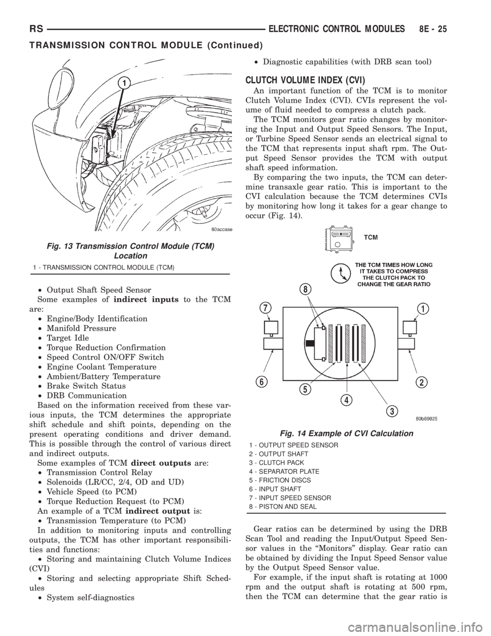
CVI calculation because the TCM determines CVIs
by monitoring how long it takes for a gear change to
occur (Fig. 14).
Gear ratios can be determined by using the DRB
Scan Tool and reading the Input/Output Speed Sen-
sor values in the ªMonitorsº display. Gear ratio can
be obtained by dividing the Input Speed Sensor value
by the Output Speed Sensor value.
For example, if the input shaft is rotating at 1000
rpm and the output shaft is rotating at 500 rpm,
then the TCM can determine that the gear ratio is
Fig. 13 Transmission Control Module (TCM)
Location
1 - TRANSMISSION CONTROL MODULE (TCM)
Fig. 14 Example of CVI Calculation
1 - OUTPUT SPEED SENSOR
2 - OUTPUT SHAFT
3 - CLUTCH PACK
4 - SEPARATOR PLATE
5 - FRICTION DISCS
6 - INPUT SHAFT
7 - INPUT SPEED SENSOR
8 - PISTON AND SEAL
RSELECTRONIC CONTROL MODULES8E-25
TRANSMISSION CONTROL MODULE (Continued)
Page 1861 of 4284
material protrude from the top of the molded plastic
battery case to provide the means for connecting the
battery to the vehicle electrical system. The battery
positive terminal post is visibly larger in diameter
than the negative terminal post, for easy identification.
The lettersPOS
andNEGare also molded into the
top of the battery case adjacent to their respective
positive and negative terminal posts for additional
identification confirmation. Refer toBattery Cables
in the index of this service manual for the location of
more information on the battery cables that connect
the battery to the vehicle electrical system.
This battery is designed to provide a safe, efficient
and reliable means of storing electrical energy in a
chemical form. This means of energy storage allows
the battery to produce the electrical energy required
to operate the engine starting system, as well as to
operate many of the other vehicle accessory systems
for limited durations while the engine and/or the
charging system are not operating. The battery is
made up of six individual cells that are connected in
series. Each cell contains positively charged plate
groups that are connected with lead straps to the
positive terminal post, and negatively charged plate
groups that are connected with lead straps to the
negative terminal post. Each plate consists of a stiff
mesh framework or grid coated with lead dioxide
(positive plate) or sponge lead (negative plate). Insu-
lators or plate separators made of a non-conductive
material are inserted between the positive and nega-
tive plates to prevent them from contacting or short-
ing against one another. These dissimilar metal
plates are submerged in a sulfuric acid and water
solution called an electrolyte.
Some factory-installed batteries have a built-in test
indicator (hydrometer). The color visible in the sight
glass of the indicator will reveal the battery condi-
tion. For more information on the use of the built-in
test indicator, refer toStandard Procedures The
factory-installed low-maintenance battery has
removable battery cell caps.Distilled water can
be added to this battery. The battery is not sealed
and has vent holes in the cell caps. The chemical
composition of the metal coated plates within the
low-maintenance battery reduces battery gassing and
water loss, at normal charge and discharge rates.
Therefore, the battery should not require additional
water in normal service. If the electrolyte level in
this battery does become low, distilled water must be
added. However, rapid loss of electrolyte can be
caused by an overcharging condition. Be certain to
diagnose the charging system after replenishing the
water in the battery for a low electrolyte condition
and before returning the vehicle to service. Refer to
Charging Systemfor additional information.The battery Group Size number, the Cold Cranking
Amperage (CCA) rating, and the Reserve Capacity
(RC) rating or Ampere-Hours (AH) rating can be
found on the original equipment battery label. Be
certain that a replacement battery has the correct
Group Size number, as well as CCA, and RC or AH
ratings that equal or exceed the original equipment
specification for the vehicle being serviced. Refer to
Battery Specificationsin this group for the loca-
tion of the proper factory-installed battery specifica-
tions. Battery sizes and ratings are discussed in more
detail below.
Group Size
²The outside dimensions and terminal placement
of the battery conform to standards established by
the Battery Council International (BCI). Each bat-
tery is assigned a BCI Group Size number to help
identify a correctly-sized replacement.
Cold Cranking Amperage
²The Cold Cranking Amperage (CCA) rating spec-
ifies how much current (in amperes) the battery can
deliver for thirty seconds at -18É C (0É F). Terminal
voltage must not fall below 7.2 volts during or after
the thirty second discharge period. The CCA required
is generally higher as engine displacement increases,
depending also upon the starter current draw
requirements.
Reserve Capacity
²The Reserve Capacity (RC) rating specifies the
time (in minutes) it takes for battery terminal volt-
age to fall below 10.5 volts, at a discharge rate of 25
amperes. RC is determined with the battery fully-
charged at 26.7É C (80É F). This rating estimates how
long the battery might last after a charging system
failure, under minimum electrical load.
Ampere-Hours
²The Ampere-Hours (AH) rating specifies the cur-
rent (in amperes) that a battery can deliver steadily
for twenty hours, with the voltage in the battery not
falling below 10.5 volts. This rating is also sometimes
identified as the twenty-hour discharge rating.
OPERATION
The battery is designed to store electrical energy in
a chemical form. When an electrical load is applied to
the terminals of the battery, an electrochemical reac-
tion occurs. This reaction causes the battery to dis-
charge electrical current from its terminals. As the
RSBATTERY SYSTEM8F-7
BATTERY (Continued)
Page 1904 of 4284
²Remote Keyless Entry Module (RKE)- Refer
toRemote Keyless Entry Modulein Power Locks
for more information.
²Electronic Vehicle Information Center
(EVIC)- Refer toElectronic Vehicle Information
Centerin Overhead Console for more information.
²Heated Seat Module (HSM)- Refer toHeated
Seat Modulein Electronic Control Modules for more
information.
²Memory Heated Seat Module (MHSM)-If
the vehicle is equipped with the Memory System,
refer toMemory Seat Mirror Module (MSMM)in
Electronic Control Modules for more information.
Refer toWiring Diagramsfor complete circuit
diagrams. Following are general descriptions of the
major components in the heated seat system.
OPERATION
The heated seat system will only operate when the
ignition switch is in the On position, and the surface
temperature at the front seat heating element sen-
sors is below the designed temperature set points of
the system. The heated seat system will not operate
in ambient temperatures greater than about 41É C
(105É F). The front seat heating elements and sensors
are hard wired to the Heated Seat Module (HSM) or
the Memory Heated Seat Module (MHSM).
The heated seat switches are hard wired to the
Body Control Module (BCM). The BCM monitors the
heated seat switch inputs, then sends heated seat
switch status messages to the HSM or MHSM over
the Programmable Communications Interface J1850
(PCI) data bus. The HSM or MHSM contains the con-
trol logic for the heated seat system. The HSM or
MHSM responds to the heated seat switch status
messages, ignition switch status messages, and the
front seat heating element sensor inputs by control-
ling the output to the front seat heating elements
through integral solid-state relays.
When a seat heater is turned on, the sensor
located on the seat cushion electric heater element
provides the HSM or MHSM with an input indicating
the surface temperature of the seat cushion. If the
surface temperature input is below the temperature
set point for the selected Low or High heated seat
switch position, the HSM or MHSM energizes the
integral solid-state relay, which supplies battery cur-
rent to the heating elements in the seat cushion and
back. When the sensor input indicates the correct
temperature set point has been achieved, the HSM or
MHSM de-energizes the solid-state relay. The HSM
or MHSM will continue to cycle the solid-state relay
as needed to maintain the temperature set point.
The HSM or MHSM and the seat heater elements
operate on non-switched battery current supplied
through the power seat fuse in the intelligent powermodule. However, the HSM or MHSM will automati-
cally turn off the heating elements if it detects an
open in the sensor circuit, a short in the heating ele-
ment circuit causing an excessive current draw, or
when the ignition switch is turned to the Off posi-
tion.
See the owner's manual in the vehicle glove box for
more information on the features, use and operation
of the heated seat system.
DRIVER HEATED SEAT
SWITCH
DESCRIPTION
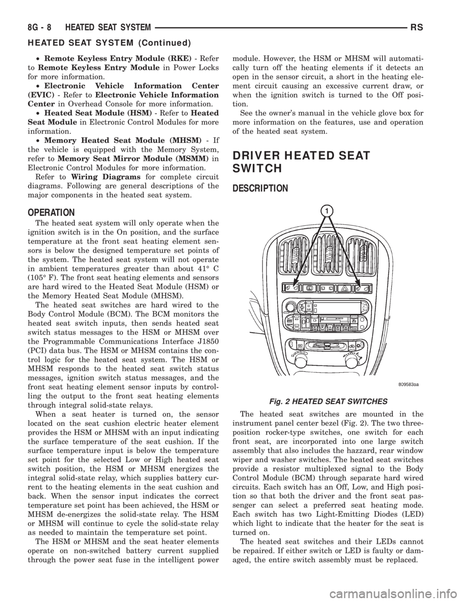
The heated seat switches are mounted in the
instrument panel center bezel (Fig. 2). The two three-
position rocker-type switches, one switch for each
front seat, are incorporated into one large switch
assembly that also includes the hazzard, rear window
wiper and washer switches. The heated seat switches
provide a resistor multiplexed signal to the Body
Control Module (BCM) through separate hard wired
circuits. Each switch has an Off, Low, and High posi-
tion so that both the driver and the front seat pas-
senger can select a preferred seat heating mode.
Each switch has two Light-Emitting Diodes (LED)
which light to indicate that the heater for the seat is
turned on.
The heated seat switches and their LEDs cannot
be repaired. If either switch or LED is faulty or dam-
aged, the entire switch assembly must be replaced.
Fig. 2 HEATED SEAT SWITCHES
8G - 8 HEATED SEAT SYSTEMRS
HEATED SEAT SYSTEM (Continued)
Page 1905 of 4284
OPERATION
There are three positions that can be selected with
each of the heated seat switches: Off, Low, or High.
When the left side of the switch rocker is fully
depressed, the Low position is selected and the high
position LED indicator illuminates. When the right
side of the switch rocker is fully depressed, the High
position is selected and the low position LED indica-
tor illuminates. When the switch rocker is moved to
its neutral position (middle), Off is selected and both
LED indicators are extinguished.
Both switches provide separate resistor multi-
plexed hard wire inputs to the BCM to indicate the
selected switch position. The BCM monitors the
switch inputs and sends heated seat switch status
messages to the Heated Seat Module (HSM) or the
Memory Heated Seat Module (MHSM) over the Pro-
grammable Communications Interface (PCI) data
bus. The HSM or MHSM responds to the heated seat
switch status messages by controlling the output to
the seat heater elements of the selected seat. The
Low heat position set point is about 36É C (97É F),
and the High heat position set point is about 41É C
(105É F).
DIAGNOSIS & TESTING - HEATED SEAT
SWITCH
For complete circuit diagrams, refer toWiring
Diagrams.
WARNING: ON VEHICLES EQUIPPED WITH AIR-
BAGS, REFER TO THE RESTRAINTS SECTION OF
THIS MANUAL BEFORE ATTEMPTING ANY STEER-
ING WHEEL, STEERING COLUMN, SEAT OR
INSTRUMENT PANEL COMPONENT DIAGNOSIS OR
SERVICE. FAILURE TO TAKE THE PROPER PRE-
CAUTIONS COULD RESULT IN ACCIDENTAL AIR-
BAG DEPLOYMENT AND POSSIBLE PERSONAL
INJURY.
(1) Check the fused ignition switch output (run)
fuse in the intelligent power module. If OK, go to
Step 2. If not OK, repair the shorted circuit or com-
ponent as required and replace the faulty fuse.
(2) Turn the ignition switch to the On position.
Check for battery voltage at the fused ignition switch
output (run) fuse in the intelligent power module. If
OK, go to Step 3. If not OK, repair the open fused
ignition switch output (run) circuit to the ignition
switch as required.
(3) Disconnect and isolate the battery negative
cable. Remove the center bezel from the instrument
panel and disconnect the instrument panel wire har-
ness connectors from the heated seat switch connec-
tor receptacle. Check for continuity between the
ground circuit cavity of the instrument panel wireharness connector for the inoperative heated seat
switch(es) and a good ground. There should be conti-
nuity. If OK, go to Step 4. If not OK, repair the open
ground circuit to ground as required.
(4) Reconnect the battery negative cable. Turn the
ignition switch to the On position. Check for battery
voltage at the fused ignition switch output (run) cir-
cuit cavity of the instrument panel wire harness con-
nector for the inoperative heated seat switch(es). If
OK, turn the ignition switch to the Off position, dis-
connect and isolate the battery negative cable, and go
to Step 5. If not OK, repair the open fused ignition
switch output (run) circuit to the intelligent power
module fuse as required.
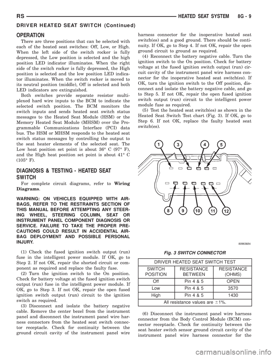
(5) Test the heated seat switch(es) as shown in the
Heated Seat Switch Test chart (Fig. 3). If OK, go to
Step 6. If not OK, replace the faulty heated seat
switch(es).
DRIVER HEATED SEAT SWITCH TEST
SWITCH
POSITIONRESISTANCE
BETWEENRESISTANCE
(OHMS)
Off Pin4&5OPEN
Low Pin4&53570
High Pin4&51430
All resistance values are61%.
(6) Disconnect the instrument panel wire harness
connector from the Body Control Module (BCM) con-
nector receptacle. Check for continuity between the
seat heater switch sensor ground circuit cavity of the
instrument panel wire harness connector for the
Fig. 3 SWITCH CONNECTOR
RSHEATED SEAT SYSTEM8G-9
DRIVER HEATED SEAT SWITCH (Continued)
Page 1908 of 4284
depressed, the Low position is selected and the high
position LED indicator illuminates. When the right
side of the switch rocker is fully depressed, the High
position is selected and the low position LED indica-
tor illuminates. When the switch rocker is moved to
its neutral position (middle), Off is selected and both
LED indicators are extinguished.
Both switches provide separate resistor multi-
plexed hard wire inputs to the BCM to indicate the
selected switch position. The BCM monitors the
switch inputs and sends heated seat switch status
messages to the Heated Seat Module (HSM) or the
Memory Heated Seat Module (MHSM) over the Pro-
grammable Communications Interface (PCI) data
bus. The HSM or MHSM responds to the heated seat
switch status messages by controlling the output to
the seat heater elements of the selected seat. The
Low heat position set point is about 36É C (97É F),
and the High heat position set point is about 41É C
(105É F).
DIAGNOSIS & TESTING - HEATED SEAT
SWITCH
For complete circuit diagrams, refer toWiring
Diagrams.
WARNING: ON VEHICLES EQUIPPED WITH AIR-
BAGS, REFER TO THE RESTRAINTS SECTION OF
THIS MANUAL BEFORE ATTEMPTING ANY STEER-
ING WHEEL, STEERING COLUMN, SEAT OR
INSTRUMENT PANEL COMPONENT DIAGNOSIS OR
SERVICE. FAILURE TO TAKE THE PROPER PRE-
CAUTIONS COULD RESULT IN ACCIDENTAL AIR-BAG DEPLOYMENT AND POSSIBLE PERSONAL
INJURY.
(1) Check the fused ignition switch output (run)
fuse in the intelligent power module. If OK, go to
Step 2. If not OK, repair the shorted circuit or com-
ponent as required and replace the faulty fuse.
(2) Turn the ignition switch to the On position.
Check for battery voltage at the fused ignition switch
output (run) fuse in the intelligent power module. If
OK, go to Step 3. If not OK, repair the open fused
ignition switch output (run) circuit to the ignition
switch as required.
(3) Disconnect and isolate the battery negative
cable. Remove the center bezel from the instrument
panel and disconnect the instrument panel wire har-
ness connectors from the heated seat switch connec-
tor receptacle. Check for continuity between the
ground circuit cavity of the instrument panel wire
harness connector for the inoperative heated seat
switch(es) and a good ground. There should be conti-
nuity. If OK, go to Step 4. If not OK, repair the open
ground circuit to ground as required.
(4) Reconnect the battery negative cable. Turn the
ignition switch to the On position. Check for battery
voltage at the fused ignition switch output (run) cir-
cuit cavity of the instrument panel wire harness con-
nector for the inoperative heated seat switch(es). If
OK, turn the ignition switch to the Off position, dis-
connect and isolate the battery negative cable, and go
to Step 5. If not OK, repair the open fused ignition
switch output (run) circuit to the intelligent power
module fuse as required.
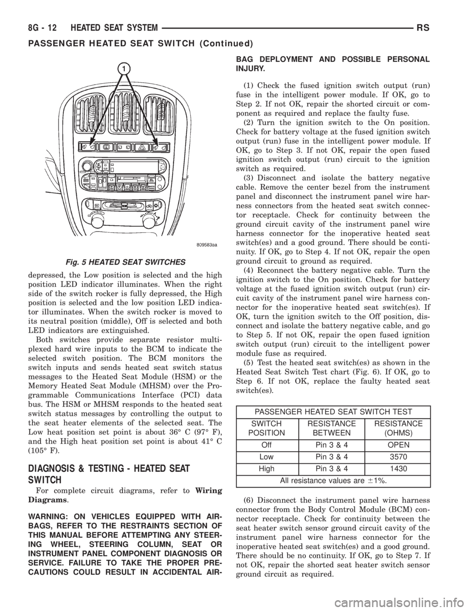
(5) Test the heated seat switch(es) as shown in the
Heated Seat Switch Test chart (Fig. 6). If OK, go to
Step 6. If not OK, replace the faulty heated seat
switch(es).
PASSENGER HEATED SEAT SWITCH TEST
SWITCH
POSITIONRESISTANCE
BETWEENRESISTANCE
(OHMS)
Off Pin3&4OPEN
Low Pin3&43570
High Pin3&41430
All resistance values are61%.
(6) Disconnect the instrument panel wire harness
connector from the Body Control Module (BCM) con-
nector receptacle. Check for continuity between the
seat heater switch sensor ground circuit cavity of the
instrument panel wire harness connector for the
inoperative heated seat switch(es) and a good ground.
There should be no continuity. If OK, go to Step 7. If
not OK, repair the shorted seat heater switch sensor
ground circuit as required.
Fig. 5 HEATED SEAT SWITCHES
8G - 12 HEATED SEAT SYSTEMRS
PASSENGER HEATED SEAT SWITCH (Continued)
Page 1911 of 4284
HORN
TABLE OF CONTENTS
page page
HORN
DESCRIPTION............................1
OPERATION.............................1
DIAGNOSIS AND TESTING..................1
HORN
DIAGNOSIS AND TESTING..................3
REMOVAL...............................4INSTALLATION............................5
HORN RELAY
DIAGNOSIS AND TESTING..................5
REMOVAL...............................5
INSTALLATION............................5
HORN SWITCH
DESCRIPTION............................5
HORN
DESCRIPTION
HORN SYSTEM
WARNING:
ON VEHICLES EQUIPPED WITH AIRBAG, REFER TO
ELECTRICAL, RESTRAINTS FOR SAFETY PRECAU-
TIONS. DISCONNECT THE NEGATIVE CABLE FROM
THE BATTERY BEFORE SERVICING COMPONENTS
INVOLVING THE AIRBAG SYSTEM. ACCIDENTAL
DEPLOYMENT OF AIRBAG AND PERSONAL INJURY
CAN RESULT.
The horn circuit consists of a horn switch, clock-
spring, horn relay, horns and intelligent power mod-
ule. The horn switch is a membrane switch located in
the airbag trim cover. The horns are located forward
of the left front wheel behind the bumper fascia.
OPERATION
The horn relay plugs into the intelligent power
module which is located in the engine compartment.
For circuit information and component locations,
refer to the appropriate wiring information. The wir-
ing information includes wiring diagrams, proper
wire and connector repair procedures, details of wire
harness routing and retention, connector pin-out
information and location views for the various wire
harness connectors, splices and grounds.
The horns will not function if the switch is
ªCLOSEDº for more than 30 seconds. Once the
switch is ªOPENº, a 20±30 second delay will occur
before the horns are functional again.
DIAGNOSIS AND TESTING
Refer to Horn System Test below. If the horn does
not sound, check horn fuse located in the intelligent
power module. If the fuse is blown, replace with the
correct fuse. If the horns fail to sound and the new
fuse blows when depressing the horn switch, a short
circuit in the horn or the horn wiring between the
fuse terminal and the horn is responsible, or a defec-
tive horn switch allowed the horn to burn out is
responsible.
If the fuse is OK, test horn relay (Refer to 8 -
ELECTRICAL/HORN/HORN RELAY - DIAGNOSIS
AND TESTING).
If the relay is OK, test horn. Refer to Horn System
Test.
CAUTION:
Continuous sounding of horn may cause horn relay
to fail.
Should the horn sound continuously:
²Unplug the horn relay from intelligent power
module.
²Refer to (Refer to 8 - ELECTRICAL/HORN/
HORN RELAY - DIAGNOSIS AND TESTING).
Refer to the appropriate wiring information. The
wiring information includes wiring diagrams, proper
wire and connector repair procedures, details of wire
harness routing and retention, connector pin-out
information and location views for the various wire
harness connectors, splices and grounds.
RSHORN8H-1