2001 CHRYSLER VOYAGER ESP
[x] Cancel search: ESPPage 1229 of 4284
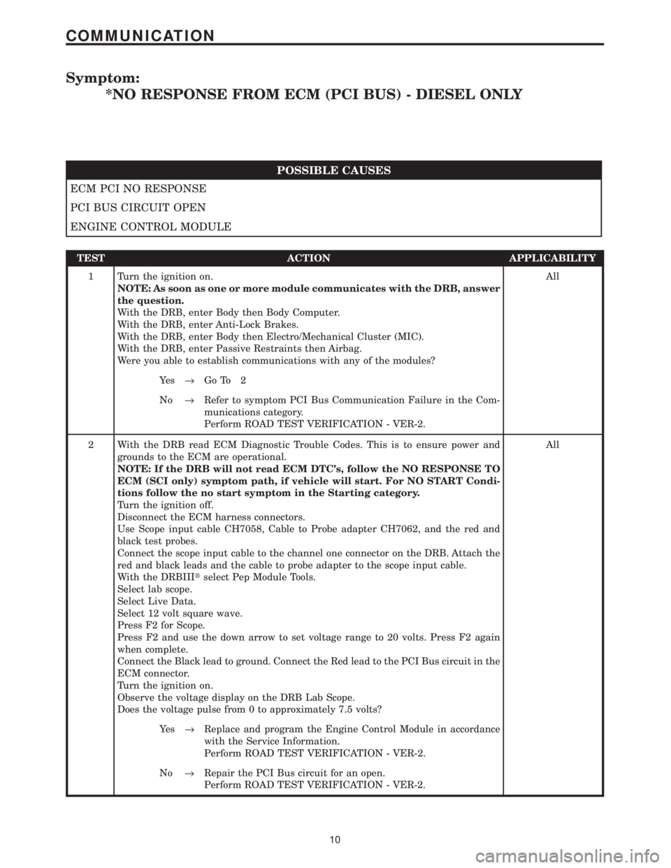
Symptom:
*NO RESPONSE FROM ECM (PCI BUS) - DIESEL ONLY
POSSIBLE CAUSES
ECM PCI NO RESPONSE
PCI BUS CIRCUIT OPEN
ENGINE CONTROL MODULE
TEST ACTION APPLICABILITY
1 Turn the ignition on.
NOTE: As soon as one or more module communicates with the DRB, answer
the question.
With the DRB, enter Body then Body Computer.
With the DRB, enter Anti-Lock Brakes.
With the DRB, enter Body then Electro/Mechanical Cluster (MIC).
With the DRB, enter Passive Restraints then Airbag.
Were you able to establish communications with any of the modules?All
Ye s®Go To 2
No®Refer to symptom PCI Bus Communication Failure in the Com-
munications category.
Perform ROAD TEST VERIFICATION - VER-2.
2 With the DRB read ECM Diagnostic Trouble Codes. This is to ensure power and
grounds to the ECM are operational.
NOTE: If the DRB will not read ECM DTC's, follow the NO RESPONSE TO
ECM (SCI only) symptom path, if vehicle will start. For NO START Condi-
tions follow the no start symptom in the Starting category.
Turn the ignition off.
Disconnect the ECM harness connectors.
Use Scope input cable CH7058, Cable to Probe adapter CH7062, and the red and
black test probes.
Connect the scope input cable to the channel one connector on the DRB. Attach the
red and black leads and the cable to probe adapter to the scope input cable.
With the DRBIIItselect Pep Module Tools.
Select lab scope.
Select Live Data.
Select 12 volt square wave.
Press F2 for Scope.
Press F2 and use the down arrow to set voltage range to 20 volts. Press F2 again
when complete.
Connect the Black lead to ground. Connect the Red lead to the PCI Bus circuit in the
ECM connector.
Turn the ignition on.
Observe the voltage display on the DRB Lab Scope.
Does the voltage pulse from 0 to approximately 7.5 volts?All
Ye s®Replace and program the Engine Control Module in accordance
with the Service Information.
Perform ROAD TEST VERIFICATION - VER-2.
No®Repair the PCI Bus circuit for an open.
Perform ROAD TEST VERIFICATION - VER-2.
10
COMMUNICATION
Page 1230 of 4284
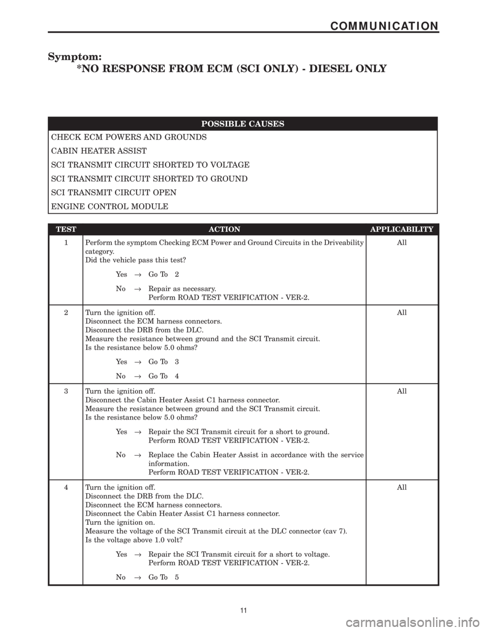
Symptom:
*NO RESPONSE FROM ECM (SCI ONLY) - DIESEL ONLY
POSSIBLE CAUSES
CHECK ECM POWERS AND GROUNDS
CABIN HEATER ASSIST
SCI TRANSMIT CIRCUIT SHORTED TO VOLTAGE
SCI TRANSMIT CIRCUIT SHORTED TO GROUND
SCI TRANSMIT CIRCUIT OPEN
ENGINE CONTROL MODULE
TEST ACTION APPLICABILITY
1 Perform the symptom Checking ECM Power and Ground Circuits in the Driveability
category.
Did the vehicle pass this test?All
Ye s®Go To 2
No®Repair as necessary.
Perform ROAD TEST VERIFICATION - VER-2.
2 Turn the ignition off.
Disconnect the ECM harness connectors.
Disconnect the DRB from the DLC.
Measure the resistance between ground and the SCI Transmit circuit.
Is the resistance below 5.0 ohms?All
Ye s®Go To 3
No®Go To 4
3 Turn the ignition off.
Disconnect the Cabin Heater Assist C1 harness connector.
Measure the resistance between ground and the SCI Transmit circuit.
Is the resistance below 5.0 ohms?All
Ye s®Repair the SCI Transmit circuit for a short to ground.
Perform ROAD TEST VERIFICATION - VER-2.
No®Replace the Cabin Heater Assist in accordance with the service
information.
Perform ROAD TEST VERIFICATION - VER-2.
4 Turn the ignition off.
Disconnect the DRB from the DLC.
Disconnect the ECM harness connectors.
Disconnect the Cabin Heater Assist C1 harness connector.
Turn the ignition on.
Measure the voltage of the SCI Transmit circuit at the DLC connector (cav 7).
Is the voltage above 1.0 volt?All
Ye s®Repair the SCI Transmit circuit for a short to voltage.
Perform ROAD TEST VERIFICATION - VER-2.
No®Go To 5
11
COMMUNICATION
Page 1231 of 4284
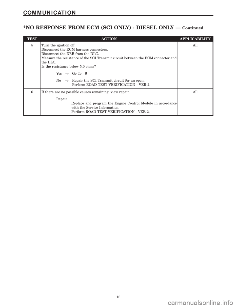
TEST ACTION APPLICABILITY
5 Turn the ignition off.
Disconnect the ECM harness connectors.
Disconnect the DRB from the DLC.
Measure the resistance of the SCI Transmit circuit between the ECM connector and
the DLC.
Is the resistance below 5.0 ohms?All
Ye s®Go To 6
No®Repair the SCI Transmit circuit for an open.
Perform ROAD TEST VERIFICATION - VER-2.
6 If there are no possible causes remaining, view repair. All
Repair
Replace and program the Engine Control Module in accordance
with the Service Information.
Perform ROAD TEST VERIFICATION - VER-2.
12
COMMUNICATION
*NO RESPONSE FROM ECM (SCI ONLY) - DIESEL ONLY ÐContinued
Page 1232 of 4284
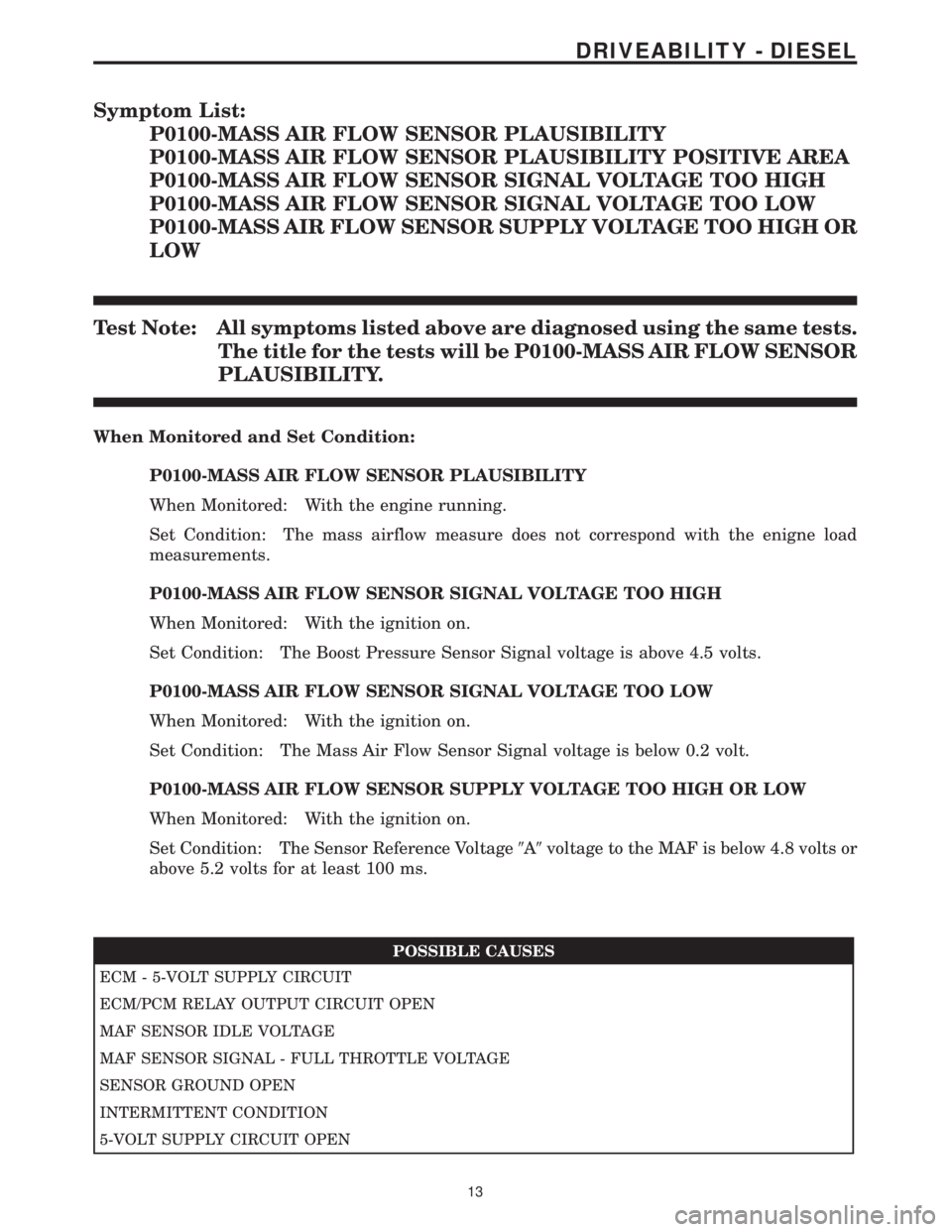
Symptom List:
P0100-MASS AIR FLOW SENSOR PLAUSIBILITY
P0100-MASS AIR FLOW SENSOR PLAUSIBILITY POSITIVE AREA
P0100-MASS AIR FLOW SENSOR SIGNAL VOLTAGE TOO HIGH
P0100-MASS AIR FLOW SENSOR SIGNAL VOLTAGE TOO LOW
P0100-MASS AIR FLOW SENSOR SUPPLY VOLTAGE TOO HIGH OR
LOW
Test Note: All symptoms listed above are diagnosed using the same tests.
The title for the tests will be P0100-MASS AIR FLOW SENSOR
PLAUSIBILITY.
When Monitored and Set Condition:
P0100-MASS AIR FLOW SENSOR PLAUSIBILITY
When Monitored: With the engine running.
Set Condition: The mass airflow measure does not correspond with the enigne load
measurements.
P0100-MASS AIR FLOW SENSOR SIGNAL VOLTAGE TOO HIGH
When Monitored: With the ignition on.
Set Condition: The Boost Pressure Sensor Signal voltage is above 4.5 volts.
P0100-MASS AIR FLOW SENSOR SIGNAL VOLTAGE TOO LOW
When Monitored: With the ignition on.
Set Condition: The Mass Air Flow Sensor Signal voltage is below 0.2 volt.
P0100-MASS AIR FLOW SENSOR SUPPLY VOLTAGE TOO HIGH OR LOW
When Monitored: With the ignition on.
Set Condition: The Sensor Reference Voltage9A9voltage to the MAF is below 4.8 volts or
above 5.2 volts for at least 100 ms.
POSSIBLE CAUSES
ECM - 5-VOLT SUPPLY CIRCUIT
ECM/PCM RELAY OUTPUT CIRCUIT OPEN
MAF SENSOR IDLE VOLTAGE
MAF SENSOR SIGNAL - FULL THROTTLE VOLTAGE
SENSOR GROUND OPEN
INTERMITTENT CONDITION
5-VOLT SUPPLY CIRCUIT OPEN
13
DRIVEABILITY - DIESEL
Page 1421 of 4284
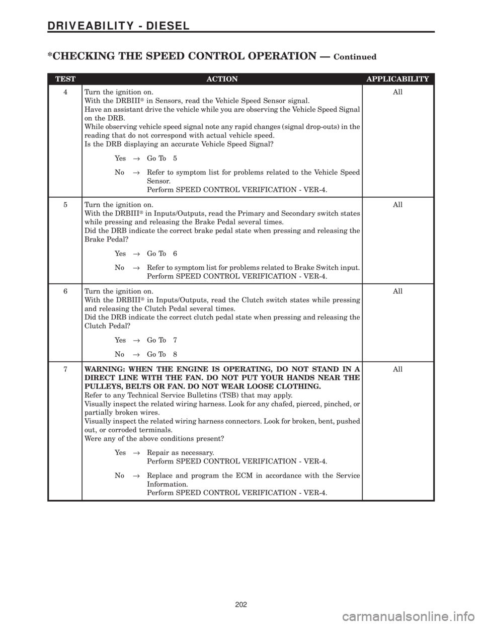
TEST ACTION APPLICABILITY
4 Turn the ignition on.
With the DRBIIItin Sensors, read the Vehicle Speed Sensor signal.
Have an assistant drive the vehicle while you are observing the Vehicle Speed Signal
on the DRB.
While observing vehicle speed signal note any rapid changes (signal drop-outs) in the
reading that do not correspond with actual vehicle speed.
Is the DRB displaying an accurate Vehicle Speed Signal?All
Ye s®Go To 5
No®Refer to symptom list for problems related to the Vehicle Speed
Sensor.
Perform SPEED CONTROL VERIFICATION - VER-4.
5 Turn the ignition on.
With the DRBIIItin Inputs/Outputs, read the Primary and Secondary switch states
while pressing and releasing the Brake Pedal several times.
Did the DRB indicate the correct brake pedal state when pressing and releasing the
Brake Pedal?All
Ye s®Go To 6
No®Refer to symptom list for problems related to Brake Switch input.
Perform SPEED CONTROL VERIFICATION - VER-4.
6 Turn the ignition on.
With the DRBIIItin Inputs/Outputs, read the Clutch switch states while pressing
and releasing the Clutch Pedal several times.
Did the DRB indicate the correct clutch pedal state when pressing and releasing the
Clutch Pedal?All
Ye s®Go To 7
No®Go To 8
7WARNING: WHEN THE ENGINE IS OPERATING, DO NOT STAND IN A
DIRECT LINE WITH THE FAN. DO NOT PUT YOUR HANDS NEAR THE
PULLEYS, BELTS OR FAN. DO NOT WEAR LOOSE CLOTHING.
Refer to any Technical Service Bulletins (TSB) that may apply.
Visually inspect the related wiring harness. Look for any chafed, pierced, pinched, or
partially broken wires.
Visually inspect the related wiring harness connectors. Look for broken, bent, pushed
out, or corroded terminals.
Were any of the above conditions present?All
Ye s®Repair as necessary.
Perform SPEED CONTROL VERIFICATION - VER-4.
No®Replace and program the ECM in accordance with the Service
Information.
Perform SPEED CONTROL VERIFICATION - VER-4.
202
DRIVEABILITY - DIESEL
*CHECKING THE SPEED CONTROL OPERATION ÐContinued
Page 1423 of 4284
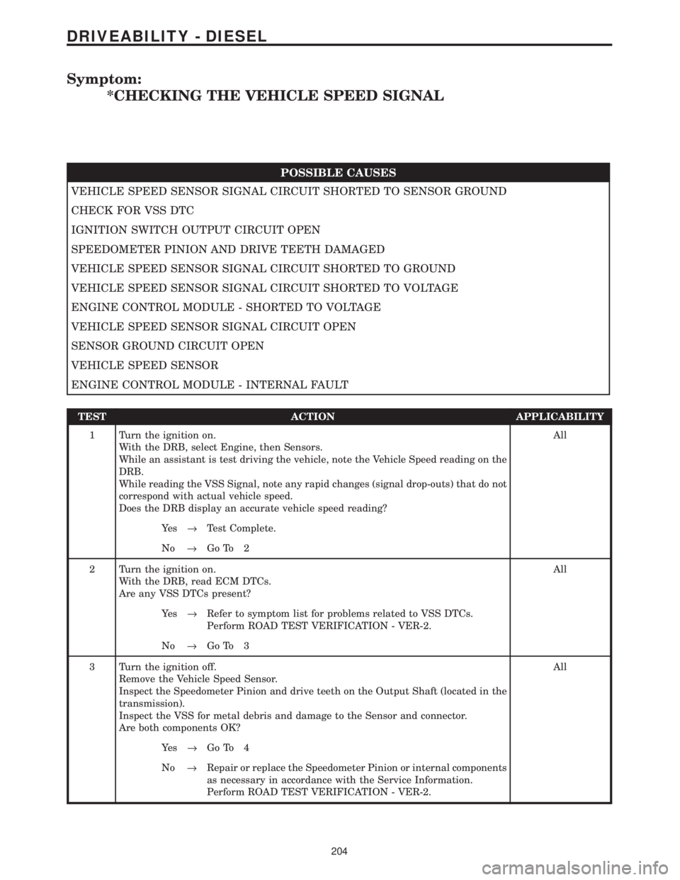
Symptom:
*CHECKING THE VEHICLE SPEED SIGNAL
POSSIBLE CAUSES
VEHICLE SPEED SENSOR SIGNAL CIRCUIT SHORTED TO SENSOR GROUND
CHECK FOR VSS DTC
IGNITION SWITCH OUTPUT CIRCUIT OPEN
SPEEDOMETER PINION AND DRIVE TEETH DAMAGED
VEHICLE SPEED SENSOR SIGNAL CIRCUIT SHORTED TO GROUND
VEHICLE SPEED SENSOR SIGNAL CIRCUIT SHORTED TO VOLTAGE
ENGINE CONTROL MODULE - SHORTED TO VOLTAGE
VEHICLE SPEED SENSOR SIGNAL CIRCUIT OPEN
SENSOR GROUND CIRCUIT OPEN
VEHICLE SPEED SENSOR
ENGINE CONTROL MODULE - INTERNAL FAULT
TEST ACTION APPLICABILITY
1 Turn the ignition on.
With the DRB, select Engine, then Sensors.
While an assistant is test driving the vehicle, note the Vehicle Speed reading on the
DRB.
While reading the VSS Signal, note any rapid changes (signal drop-outs) that do not
correspond with actual vehicle speed.
Does the DRB display an accurate vehicle speed reading?All
Ye s®Test Complete.
No®Go To 2
2 Turn the ignition on.
With the DRB, read ECM DTCs.
Are any VSS DTCs present?All
Ye s®Refer to symptom list for problems related to VSS DTCs.
Perform ROAD TEST VERIFICATION - VER-2.
No®Go To 3
3 Turn the ignition off.
Remove the Vehicle Speed Sensor.
Inspect the Speedometer Pinion and drive teeth on the Output Shaft (located in the
transmission).
Inspect the VSS for metal debris and damage to the Sensor and connector.
Are both components OK?All
Ye s®Go To 4
No®Repair or replace the Speedometer Pinion or internal components
as necessary in accordance with the Service Information.
Perform ROAD TEST VERIFICATION - VER-2.
204
DRIVEABILITY - DIESEL
Page 1427 of 4284
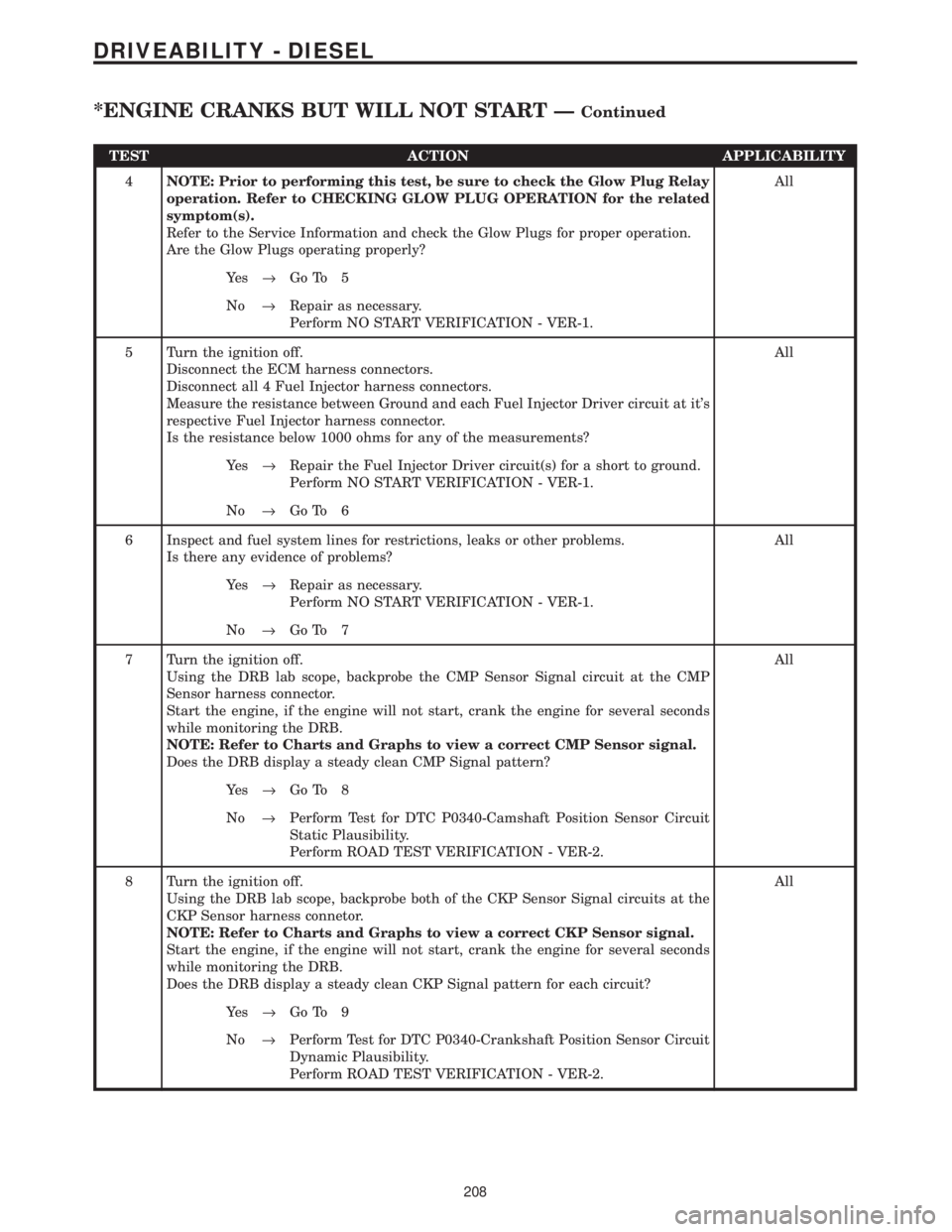
TEST ACTION APPLICABILITY
4NOTE: Prior to performing this test, be sure to check the Glow Plug Relay
operation. Refer to CHECKING GLOW PLUG OPERATION for the related
symptom(s).
Refer to the Service Information and check the Glow Plugs for proper operation.
Are the Glow Plugs operating properly?All
Ye s®Go To 5
No®Repair as necessary.
Perform NO START VERIFICATION - VER-1.
5 Turn the ignition off.
Disconnect the ECM harness connectors.
Disconnect all 4 Fuel Injector harness connectors.
Measure the resistance between Ground and each Fuel Injector Driver circuit at it's
respective Fuel Injector harness connector.
Is the resistance below 1000 ohms for any of the measurements?All
Ye s®Repair the Fuel Injector Driver circuit(s) for a short to ground.
Perform NO START VERIFICATION - VER-1.
No®Go To 6
6 Inspect and fuel system lines for restrictions, leaks or other problems.
Is there any evidence of problems?All
Ye s®Repair as necessary.
Perform NO START VERIFICATION - VER-1.
No®Go To 7
7 Turn the ignition off.
Using the DRB lab scope, backprobe the CMP Sensor Signal circuit at the CMP
Sensor harness connector.
Start the engine, if the engine will not start, crank the engine for several seconds
while monitoring the DRB.
NOTE: Refer to Charts and Graphs to view a correct CMP Sensor signal.
Does the DRB display a steady clean CMP Signal pattern?All
Ye s®Go To 8
No®Perform Test for DTC P0340-Camshaft Position Sensor Circuit
Static Plausibility.
Perform ROAD TEST VERIFICATION - VER-2.
8 Turn the ignition off.
Using the DRB lab scope, backprobe both of the CKP Sensor Signal circuits at the
CKP Sensor harness connetor.
NOTE: Refer to Charts and Graphs to view a correct CKP Sensor signal.
Start the engine, if the engine will not start, crank the engine for several seconds
while monitoring the DRB.
Does the DRB display a steady clean CKP Signal pattern for each circuit?All
Ye s®Go To 9
No®Perform Test for DTC P0340-Crankshaft Position Sensor Circuit
Dynamic Plausibility.
Perform ROAD TEST VERIFICATION - VER-2.
208
DRIVEABILITY - DIESEL
*ENGINE CRANKS BUT WILL NOT START ÐContinued
Page 1439 of 4284
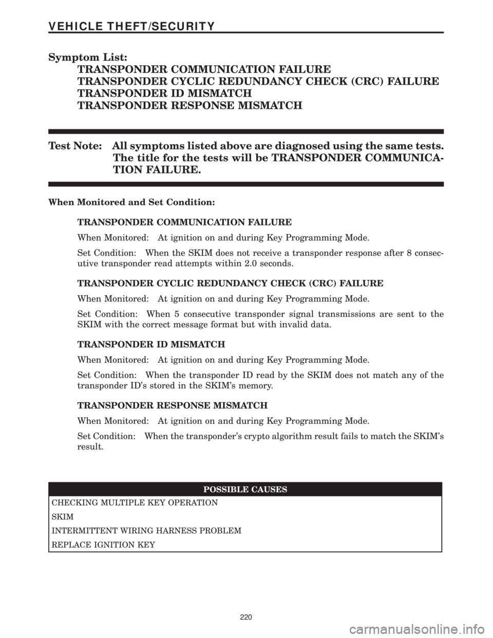
Symptom List:
TRANSPONDER COMMUNICATION FAILURE
TRANSPONDER CYCLIC REDUNDANCY CHECK (CRC) FAILURE
TRANSPONDER ID MISMATCH
TRANSPONDER RESPONSE MISMATCH
Test Note: All symptoms listed above are diagnosed using the same tests.
The title for the tests will be TRANSPONDER COMMUNICA-
TION FAILURE.
When Monitored and Set Condition:
TRANSPONDER COMMUNICATION FAILURE
When Monitored: At ignition on and during Key Programming Mode.
Set Condition: When the SKIM does not receive a transponder response after 8 consec-
utive transponder read attempts within 2.0 seconds.
TRANSPONDER CYCLIC REDUNDANCY CHECK (CRC) FAILURE
When Monitored: At ignition on and during Key Programming Mode.
Set Condition: When 5 consecutive transponder signal transmissions are sent to the
SKIM with the correct message format but with invalid data.
TRANSPONDER ID MISMATCH
When Monitored: At ignition on and during Key Programming Mode.
Set Condition: When the transponder ID read by the SKIM does not match any of the
transponder ID's stored in the SKIM's memory.
TRANSPONDER RESPONSE MISMATCH
When Monitored: At ignition on and during Key Programming Mode.
Set Condition: When the transponder's crypto algorithm result fails to match the SKIM's
result.
POSSIBLE CAUSES
CHECKING MULTIPLE KEY OPERATION
SKIM
INTERMITTENT WIRING HARNESS PROBLEM
REPLACE IGNITION KEY
220
VEHICLE THEFT/SECURITY