2001 CHRYSLER VOYAGER ESP
[x] Cancel search: ESPPage 1923 of 4284

INSTALLATION - 3.3/3.8L
(1) Install coil over studs on bracket.
(2) Install 2 bolts to ignition coil.
(3) Install 2 nuts to the ignition coil studs. Tighten
nuts and bolts.
(4) Connect the electrical connector to the ignition
coil.
(5) Install the ignition cables to the ignition coil.
(6) Reposition the Power steering reservoir. Slide
bracket over the mounting stud (Fig. 12).
(7) Install 2 bolts the Power steering reservoir to
intake manifold.
(8) Tighten the lower nut to stud on ignition coil
bracket.
(9) Install the throttle and speed control cables to
clip.
(10) Connect the negative battery cable.
KNOCK SENSOR
DESCRIPTION
The knock sensor threads into the cylinder block.
The knock sensor is designed to detect engine vibra-
tion that is caused by detonation.
OPERATION
When the knock sensor detects a knock in one of
the cylinders, it sends an input signal to the PCM. In
response, the PCM retards ignition timing for all cyl-
inders by a scheduled amount.Knock sensors contain a piezoelectric material
which constantly vibrates and sends an input voltage
(signal) to the PCM while the engine operates. As the
intensity of the crystal's vibration increases, the
knock sensor output voltage also increases.
The voltage signal produced by the knock sensor
increases with the amplitude of vibration. The PCM
receives as an input the knock sensor voltage signal.
If the signal rises above a predetermined level, the
PCM will store that value in memory and retard
ignition timing to reduce engine knock. If the knock
sensor voltage exceeds a preset value, the PCM
retards ignition timing for all cylinders. It is not a
selective cylinder retard.
The PCM ignores knock sensor input during engine
idle conditions. Once the engine speed exceeds a
specified value, knock retard is allowed.
Knock retard uses its own short term and long
term memory program.
Long term memory stores previous detonation
information in its battery-backed RAM. The maxi-
mum authority that long term memory has over tim-
ing retard can be calibrated.
Short term memory is allowed to retard timing up
to a preset amount under all operating conditions (as
long as rpm is above the minimum rpm) except WOT.
The PCM, using short term memory, can respond
quickly to retard timing when engine knock is
detected. Short term memory is lost any time the
ignition key is turned off.
NOTE: Over or under tightening affects knock sen-
sor performance, possibly causing improper spark
control.
REMOVAL - 2.4L
The knock sensor threads into the side of the cyl-
inder block in front of the starter (Fig. 13).
(1) Disconnect electrical connector from knock sen-
sor.
(2) Use a crow foot socket to remove the knock
sensors.
REMOVAL - 3.8L
The knock sensor threads into the side of the cyl-
inder block in the rear.
(1) Disconnect the negative battery cable.
(2) Raise vehicle and support.
(3) On All Wheel Drive vehicles remove the PTU
(Power Transfer Unit), refer to the Transmission sec-
tion for more information.
(4) Disconnect electrical connector from knock sen-
sor.
(5) Use a crow foot socket to remove the knock
sensor.
Fig. 12 IGNITION COIL BRACKET 3.3/3.8L
RSIGNITION CONTROL8I-7
IGNITION COIL (Continued)
Page 1929 of 4284
CONDITIONS
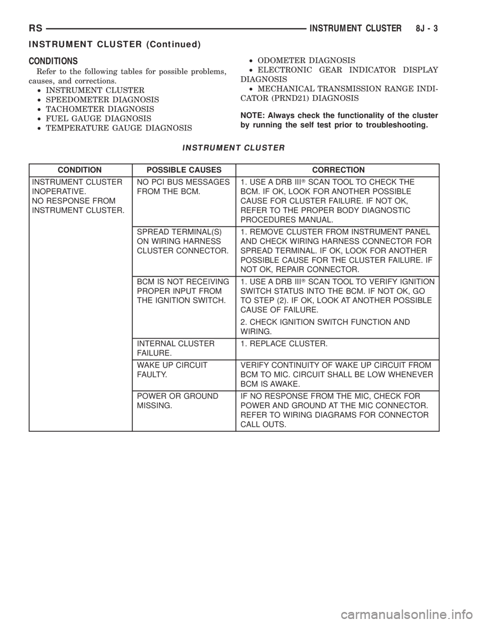
Refer to the following tables for possible problems,
causes, and corrections.
²INSTRUMENT CLUSTER
²SPEEDOMETER DIAGNOSIS
²TACHOMETER DIAGNOSIS
²FUEL GAUGE DIAGNOSIS
²TEMPERATURE GAUGE DIAGNOSIS²ODOMETER DIAGNOSIS
²ELECTRONIC GEAR INDICATOR DISPLAY
DIAGNOSIS
²MECHANICAL TRANSMISSION RANGE INDI-
CATOR (PRND21) DIAGNOSIS
NOTE: Always check the functionality of the cluster
by running the self test prior to troubleshooting.
INSTRUMENT CLUSTER
CONDITION POSSIBLE CAUSES CORRECTION
INSTRUMENT CLUSTER
INOPERATIVE.
NO RESPONSE FROM
INSTRUMENT CLUSTER.NO PCI BUS MESSAGES
FROM THE BCM.1. USE A DRB IIITSCAN TOOL TO CHECK THE
BCM. IF OK, LOOK FOR ANOTHER POSSIBLE
CAUSE FOR CLUSTER FAILURE. IF NOT OK,
REFER TO THE PROPER BODY DIAGNOSTIC
PROCEDURES MANUAL.
SPREAD TERMINAL(S)
ON WIRING HARNESS
CLUSTER CONNECTOR.1. REMOVE CLUSTER FROM INSTRUMENT PANEL
AND CHECK WIRING HARNESS CONNECTOR FOR
SPREAD TERMINAL. IF OK, LOOK FOR ANOTHER
POSSIBLE CAUSE FOR THE CLUSTER FAILURE. IF
NOT OK, REPAIR CONNECTOR.
BCM IS NOT RECEIVING
PROPER INPUT FROM
THE IGNITION SWITCH.1. USE A DRB IIITSCAN TOOL TO VERIFY IGNITION
SWITCH STATUS INTO THE BCM. IF NOT OK, GO
TO STEP (2). IF OK, LOOK AT ANOTHER POSSIBLE
CAUSE OF FAILURE.
2. CHECK IGNITION SWITCH FUNCTION AND
WIRING.
INTERNAL CLUSTER
FAILURE.1. REPLACE CLUSTER.
WAKE UP CIRCUIT
FAULTY.VERIFY CONTINUITY OF WAKE UP CIRCUIT FROM
BCM TO MIC. CIRCUIT SHALL BE LOW WHENEVER
BCM IS AWAKE.
POWER OR GROUND
MISSING.IF NO RESPONSE FROM THE MIC, CHECK FOR
POWER AND GROUND AT THE MIC CONNECTOR.
REFER TO WIRING DIAGRAMS FOR CONNECTOR
CALL OUTS.
RSINSTRUMENT CLUSTER8J-3
INSTRUMENT CLUSTER (Continued)
Page 1970 of 4284
OVERHEAD CONSOLE
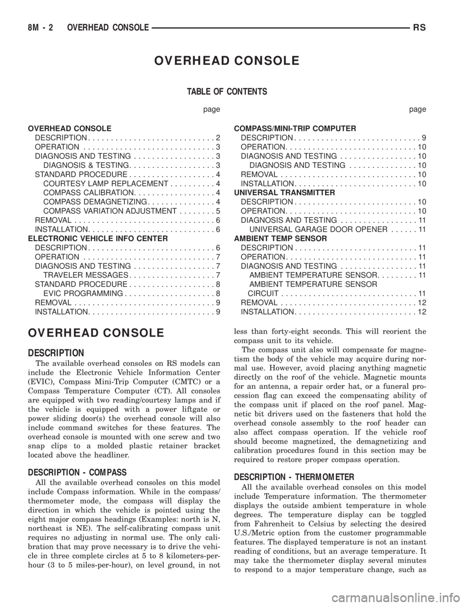
TABLE OF CONTENTS
page page
OVERHEAD CONSOLE
DESCRIPTION............................2
OPERATION.............................3
DIAGNOSIS AND TESTING..................3
DIAGNOSIS & TESTING...................3
STANDARD PROCEDURE...................4
COURTESY LAMP REPLACEMENT..........4
COMPASS CALIBRATION..................4
COMPASS DEMAGNETIZING...............4
COMPASS VARIATION ADJUSTMENT........5
REMOVAL...............................6
INSTALLATION............................6
ELECTRONIC VEHICLE INFO CENTER
DESCRIPTION............................6
OPERATION.............................7
DIAGNOSIS AND TESTING..................7
TRAVELER MESSAGES...................7
STANDARD PROCEDURE...................8
EVIC PROGRAMMING....................8
REMOVAL...............................9
INSTALLATION............................9COMPASS/MINI-TRIP COMPUTER
DESCRIPTION............................9
OPERATION.............................10
DIAGNOSIS AND TESTING.................10
DIAGNOSIS AND TESTING...............10
REMOVAL..............................10
INSTALLATION...........................10
UNIVERSAL TRANSMITTER
DESCRIPTION...........................10
OPERATION.............................10
DIAGNOSIS AND TESTING.................11
UNIVERSAL GARAGE DOOR OPENER......11
AMBIENT TEMP SENSOR
DESCRIPTION...........................11
OPERATION.............................11
DIAGNOSIS AND TESTING.................11
AMBIENT TEMPERATURE SENSOR.........11
AMBIENT TEMPERATURE SENSOR
CIRCUIT..............................11
REMOVAL..............................12
INSTALLATION...........................12
OVERHEAD CONSOLE
DESCRIPTION
The available overhead consoles on RS models can
include the Electronic Vehicle Information Center
(EVIC), Compass Mini-Trip Computer (CMTC) or a
Compass Temperature Computer (CT). All consoles
are equipped with two reading/courtesy lamps and if
the vehicle is equipped with a power liftgate or
power sliding door(s) the overhead console will also
include command switches for these features. The
overhead console is mounted with one screw and two
snap clips to a molded plastic retainer bracket
located above the headliner.
DESCRIPTION - COMPASS
All the available overhead consoles on this model
include Compass information. While in the compass/
thermometer mode, the compass will display the
direction in which the vehicle is pointed using the
eight major compass headings (Examples: north is N,
northeast is NE). The self-calibrating compass unit
requires no adjusting in normal use. The only cali-
bration that may prove necessary is to drive the vehi-
cle in three complete circles at 5 to 8 kilometers-per-
hour (3 to 5 miles-per-hour), on level ground, in notless than forty-eight seconds. This will reorient the
compass unit to its vehicle.
The compass unit also will compensate for magne-
tism the body of the vehicle may acquire during nor-
mal use. However, avoid placing anything magnetic
directly on the roof of the vehicle. Magnetic mounts
for an antenna, a repair order hat, or a funeral pro-
cession flag can exceed the compensating ability of
the compass unit if placed on the roof panel. Mag-
netic bit drivers used on the fasteners that hold the
overhead console assembly to the roof header can
also affect compass operation. If the vehicle roof
should become magnetized, the demagnetizing and
calibration procedures found in this section may be
required to restore proper compass operation.DESCRIPTION - THERMOMETER
All the available overhead consoles on this model
include Temperature information. The thermometer
displays the outside ambient temperature in whole
degrees. The temperature display can be toggled
from Fahrenheit to Celsius by selecting the desired
U.S./Metric option from the customer programmable
features. The displayed temperature is not an instant
reading of conditions, but an average temperature. It
may take the thermometer display several minutes
to respond to a major temperature change, such as
8M - 2 OVERHEAD CONSOLERS
Page 1975 of 4284
The EVIC module contains a central processing
unit and interfaces with other electronic modules in
the vehicle over the Programmable Communications
Interface (PCI) J1850 data bus circuit. The PCI data
bus circuit allows the sharing of sensor information.
This helps to reduce wire harness complexity, reduce
internal controller hardware, and reduce component
sensor current loads. At the same time, this system
provides increased reliability, enhanced diagnostics,
and allows the addition of many new feature capabil-
ities.
The EVIC ªMenuº push button provides the vehicle
operator with a user interface, which allows the
selection of several optional customer programmable
electronic features to suit individual preferences.
Refer toELECTRONIC VEHICLE INFORMA-
TION CENTER PROGRAMMINGin the Service
Procedures section of this group for more information
on the customer programmable feature options.
If the vehicle is equipped with the optional
Homelinkttransceiver, the EVIC will also display
messages and an icon indicating when the
Homelinkttransceiver is being trained, which of the
three transmitter buttons is transmitting, and when
the transceiver is cleared.
Data input for all EVIC functions, including VFD
dimming level, is received through the J1850 PCI
data bus circuit. The EVIC module uses its internal
programming and all of its data inputs to calculate
and display the requested data. If the data displayed
is incorrect, perform the self-diagnostic tests as
described in this group. If these tests prove inconclu-
sive, the use of a DRBIIItscan tool and the proper
Diagnostic Procedures manual are recommended for
further testing of the EVIC module and the J1850
PCI data bus circuit.
The EVIC module cannot be repaired, and is avail-
able for service only as a unit. This unit includes the
plastic module and display lens. If any of these com-
ponents is faulty or damaged, the complete EVIC
module must be replaced.
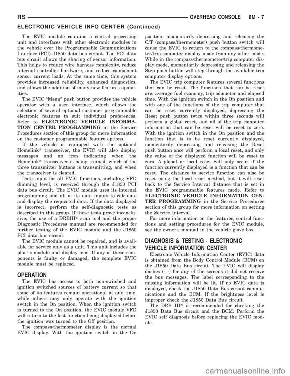
OPERATION
The EVIC has access to both non-switched and
ignition switched sources of battery current so that
some of its features remain operational at any time,
while others may only operate with the ignition
switch in the On position. When the ignition switch
is turned to the On position, the EVIC module VFD
will return to the last function being displayed before
the ignition was turned to the Off position.
The compass/thermometer display is the normal
EVIC display. With the ignition switch in the Onposition, momentarily depressing and releasing the
C/T (compass/thermometer) push button switch will
cause the EVIC to return to the compass/thermome-
ter/trip computer display mode from any other mode.
While in the compass/thermometer/trip computer dis-
play mode, momentarily depressing and releasing the
Step push button will step through the available trip
computer display options.
The EVIC trip computer features several functions
that can be reset. The functions that can be reset
are: average fuel economy, trip odometer and elapsed
time. With the ignition switch in the On position and
with one of the functions of the trip computer that
can be reset currently displayed, depressing the
Reset push button twice within three seconds will
perform a global reset, and all of the trip computer
information that can be reset will be reset to zero.
With the ignition switch in the On position and the
function that is to be reset currently displayed,
momentarily depressing and releasing the Reset
push button once will perform a local reset, and only
the value of the displayed function will be reset to
zero. A global or local reset will only occur if the
function currently displayed is a function that can be
reset. The distance to service function can also be
reset using the local reset method, but it will reset
back to the Service Interval distance that is set in
the EVIC programmable features mode. Refer to
ELECTRONIC VEHICLE INFORMATION CEN-
TER PROGRAMMINGin the Service Procedures
section of this group for more information on setting
the Service Interval.
For more information on the features, control func-
tions and setting procedures for the EVIC module,
see the owner's manual in the vehicle glove box.
DIAGNOSIS & TESTING - ELECTRONIC
VEHICLE INFORMATION CENTER
Electronic Vehicle Information Center (EVIC) data
is obtained from the Body Control Module (BCM) on
the J1850 Data Bus circuit. The EVIC will display
dashes (- -) for any of the screens it did not receive
the bus messages. The label corresponding to the
missing information will be lit. If no EVIC data is
displayed, check the J1850 Data Bus circuit commu-
nications and the BCM. If the brightness level is
improper check the J1850 Data Bus circuit.
The DRB IIItis recommended for checking the
J1850 Data Bus circuit and the BCM. Perform the
EVIC self diagnosis before replacing the EVIC mod-
ule.
RSOVERHEAD CONSOLE8M-7
ELECTRONIC VEHICLE INFO CENTER (Continued)
Page 1976 of 4284
STANDARD PROCEDURE - ELECTRONIC
VEHICLE INFORMATION CENTER
PROGRAMMING
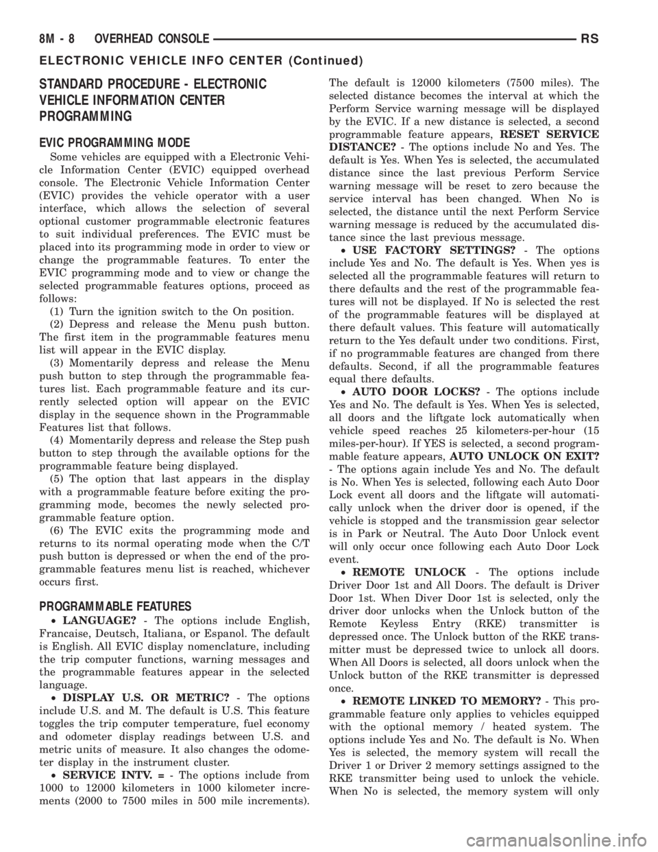
EVIC PROGRAMMING MODE
Some vehicles are equipped with a Electronic Vehi-
cle Information Center (EVIC) equipped overhead
console. The Electronic Vehicle Information Center
(EVIC) provides the vehicle operator with a user
interface, which allows the selection of several
optional customer programmable electronic features
to suit individual preferences. The EVIC must be
placed into its programming mode in order to view or
change the programmable features. To enter the
EVIC programming mode and to view or change the
selected programmable features options, proceed as
follows:
(1) Turn the ignition switch to the On position.
(2) Depress and release the Menu push button.
The first item in the programmable features menu
list will appear in the EVIC display.
(3) Momentarily depress and release the Menu
push button to step through the programmable fea-
tures list. Each programmable feature and its cur-
rently selected option will appear on the EVIC
display in the sequence shown in the Programmable
Features list that follows.
(4) Momentarily depress and release the Step push
button to step through the available options for the
programmable feature being displayed.
(5) The option that last appears in the display
with a programmable feature before exiting the pro-
gramming mode, becomes the newly selected pro-
grammable feature option.
(6) The EVIC exits the programming mode and
returns to its normal operating mode when the C/T
push button is depressed or when the end of the pro-
grammable features menu list is reached, whichever
occurs first.
PROGRAMMABLE FEATURES
²LANGUAGE?- The options include English,
Francaise, Deutsch, Italiana, or Espanol. The default
is English. All EVIC display nomenclature, including
the trip computer functions, warning messages and
the programmable features appear in the selected
language.
²DISPLAY U.S. OR METRIC?- The options
include U.S. and M. The default is U.S. This feature
toggles the trip computer temperature, fuel economy
and odometer display readings between U.S. and
metric units of measure. It also changes the odome-
ter display in the instrument cluster.
²SERVICE INTV. =- The options include from
1000 to 12000 kilometers in 1000 kilometer incre-
ments (2000 to 7500 miles in 500 mile increments).The default is 12000 kilometers (7500 miles). The
selected distance becomes the interval at which the
Perform Service warning message will be displayed
by the EVIC. If a new distance is selected, a second
programmable feature appears,RESET SERVICE
DISTANCE?- The options include No and Yes. The
default is Yes. When Yes is selected, the accumulated
distance since the last previous Perform Service
warning message will be reset to zero because the
service interval has been changed. When No is
selected, the distance until the next Perform Service
warning message is reduced by the accumulated dis-
tance since the last previous message.
²USE FACTORY SETTINGS?- The options
include Yes and No. The default is Yes. When yes is
selected all the programmable features will return to
there defaults and the rest of the programmable fea-
tures will not be displayed. If No is selected the rest
of the programmable features will be displayed at
there default values. This feature will automatically
return to the Yes default under two conditions. First,
if no programmable features are changed from there
defaults. Second, if all the programmable features
equal there defaults.
²AUTO DOOR LOCKS?- The options include
Yes and No. The default is Yes. When Yes is selected,
all doors and the liftgate lock automatically when
vehicle speed reaches 25 kilometers-per-hour (15
miles-per-hour). If YES is selected, a second program-
mable feature appears,AUTO UNLOCK ON EXIT?
- The options again include Yes and No. The default
is No. When Yes is selected, following each Auto Door
Lock event all doors and the liftgate will automati-
cally unlock when the driver door is opened, if the
vehicle is stopped and the transmission gear selector
is in Park or Neutral. The Auto Door Unlock event
will only occur once following each Auto Door Lock
event.
²REMOTE UNLOCK- The options include
Driver Door 1st and All Doors. The default is Driver
Door 1st. When Diver Door 1st is selected, only the
driver door unlocks when the Unlock button of the
Remote Keyless Entry (RKE) transmitter is
depressed once. The Unlock button of the RKE trans-
mitter must be depressed twice to unlock all doors.
When All Doors is selected, all doors unlock when the
Unlock button of the RKE transmitter is depressed
once.
²REMOTE LINKED TO MEMORY?- This pro-
grammable feature only applies to vehicles equipped
with the optional memory / heated system. The
options include Yes and No. The default is No. When
Yes is selected, the memory system will recall the
Driver 1 or Driver 2 memory settings assigned to the
RKE transmitter being used to unlock the vehicle.
When No is selected, the memory system will only
8M - 8 OVERHEAD CONSOLERS
ELECTRONIC VEHICLE INFO CENTER (Continued)
Page 1978 of 4284
OPERATION
The Compass Mini-Trip Computer (CMTC), Com-
pass Temperature (CT) module in the overhead con-
sole has buttons used to select various functions. The
CMTC, CT selector buttons will not operate until the
ignition is in the RUN position.
When the ignition switch is first turned to the
RUN position the CMTC, CT display;
²Blanks momentarily
²
All segments of the VFD will light for one second
²Blanks momentarily
²Returns to the last mode setting selected before
the ignition was last switched OFF.
DIAGNOSIS & TESTING - COMPASS MINI-TRIP
COMPUTER
Compass Mini-Trip Computer (CMTC) and Com-
pass Temperature (CT) data is obtained from the
Body Control Module (BCM) on the J1850 Data Bus
circuit. The CMTC and CT will display dashes (- -)
for any of the screens it did not receive the bus mes-
sages. The label corresponding to the missing infor-
mation will be lit. If no compass mini-trip computer
data is displayed, check the J1850 Data Bus circuit
communications and the BCM. If the brightness level
is improper check the J1850 Data Bus circuit.
The DRB IIItis recommended for checking the
J1850 Data Bus circuit and the BCM. Perform the
CMTC, CT self diagnosis before replacing the CMTC
or CT module.
REMOVAL
(1) Disconnect and isolate the battery negative
cable.
(2) Remove overhead console. Refer to Overhead
Console Removal and Installation in this section(Re-
fer to 8 - ELECTRICAL/OVERHEAD CONSOLE -
REMOVAL) .
(3) Remove the screws holding Compass Mini-Trip
Computer module in the overhead console.
(4) Remove CMTC module from console assembly.
INSTALLATION
(1) Position the compass mini-trip computer mod-
ule in the overhead console.
(2) Install the ten screws holding the compass
mini-trip computer module in the overhead console.
(3) Install the overhead console. Refer to Overhead
Console Removal and Installation in this section.
(4) Connect the battery negative cable.
NOTE: If a new module has been installed, the com-
pass will have to be calibrated and the variance set.
Refer to Compass Variation Adjustment and Com-
pass Calibration in the Service Procedures section
of this group for the procedures.
UNIVERSAL TRANSMITTER
DESCRIPTION
On some RS models a Homelinkttransceiver is
standard factory-installed equipment. The Homelinkt
transceiver is integral to the Electronic Vehicle Infor-
mation Center (EVIC) and the Compass Mini-Trip
Computer (CMTC), which is located in the overhead
console. The only visible component of the Homelinkt
are the three transmitter push buttons centered
between the modules push buttons located just rear-
ward of the display screen in the overhead console.
The three Homelinkttransmitter push buttons are
identified with one, two or three light indicators so
that they be easily identified by sight or by feel.
Each of the three Homelinkttransmitter push but-
tons controls an independent radio transmitter chan-
nel. Each of these three channels can be trained to
transmit a different radio frequency signal for the
remote operation of garage door openers, motorized
gate openers, home or office lighting, security sys-
tems or just about any other device that can be
equipped with a radio receiver in the 286 to 399
MegaHertz (MHz) frequency range for remote opera-
tion. The Homelinktis capable of operating systems
using either rolling code or non-rolling code technol-
ogy.
The electronics module displays messages and a
small house-shaped icon with one, two or three dots
corresponding to the three transmitter buttons to
indicate the status of the Homelinkt. The EVIC mes-
sages are:
²Cleared Channels- Indicates that all of the
transmitter codes stored in the Homelinkthave been
successfully cleared.
²Training- Indicates that the Homelinktis in
its transmitter learning mode.
²Trained- Indicates that the Homelinkthas
successfully acquired a new transmitter code.
²Transmit- Indicates that a trained Homelinkt
transmitter button has been depressed and that the
Homelinktis transmitting.
The Homelinktcannot be repaired, and is avail-
able for service only as a unit with the EVIC or
CMTC modules. If any of these components is faulty
or damaged, the complete EVIC or CMTC module
must be replaced.
OPERATION
The Homelinktoperates on a non-switched source
of battery current so the unit will remain functional,
regardless of the ignition switch position. For more
information on the features, programming procedures
and operation of the Homelinkt, see the owner's
manual in the vehicle glove box.
8M - 10 OVERHEAD CONSOLERS
COMPASS/MINI-TRIP COMPUTER (Continued)
Page 1979 of 4284
DIAGNOSIS & TESTING - HOMELINKT
If the Homelinktis inoperative, but the Electronic
Vehicle Information Center (EVIC) or Compass Mini-
Trip Computer is operating normally, see the owner's
manual in the vehicle glove box for instructions on
training the Homelinkt. Retrain the Homelinktwith
a known good transmitter as instructed in the own-
er's manual and test the Homelinktoperation again.
If the unit is still inoperative, replace the faulty
Homelinktand EVIC/CMTC module as a unit. If
both the Homelinktand the EVIC/CMTC module are
inoperative, refer toOverhead Console Diagnosis
and Testingearlier in this group for further diagno-
sis. For complete circuit diagrams, refer toOver-
head Consolein Wiring Diagrams.
AMBIENT TEMP SENSOR
DESCRIPTION
Ambient air temperature is monitored by the over-
head console through ambient temperature messages
received from the Front Control Module (FCM) over
the Programmable Communications Interface (PCI)
J1850 data bus circuit. The FCM receives a hard
wired input from the ambient temperature sensor.
The ambient temperature sensor is a variable resis-
tor mounted to a bracket that is secured with a screw
to the right side of the headlamp mounting module
grille opening, behind the radiator grille and in front
of the engine compartment.
Refer toFront Control Modulein Electronic
Control Modules. For complete circuit diagrams, refer
to the appropriate wiring information. The ambient
temperature sensor cannot be adjusted or repaired
and, if faulty or damaged, it must be replaced.
OPERATION
The ambient temperature sensor is a variable
resistor that operates on a five-volt reference signal
sent to it by the Front Control Module. The resis-
tance in the sensor changes as temperature changes,
changing the temperature sensor signal circuit volt-
age to the Front Control Module. Based upon the
resistance in the sensor, the Front Control Module
senses a specific voltage on the temperature sensor
signal circuit, which it is programmed to correspond
to a specific temperature. The Front Control Module
then sends the proper ambient temperature mes-
sages to the EVIC, CMTC over the PCI J1850 data
bus.
The thermometer function is supported by the
ambient temperature sensor, a wiring circuit, the
Front Control Module, the Programmable Communi-
cations Interface (PCI) data bus, and a portion of the
Electronics module. If any portion of the ambienttemperature sensor circuit fails, the Front Control
Module will self-diagnose the circuit.
The ambient temperature sensor circuit can also be
diagnosed by referring toDiagnosis and Testing -
Ambient Temperature Sensor, and Diagnosis
and Testing - Ambient Temperature Sensor Cir-
cuit. If the temperature sensor and circuit are con-
firmed to be OK, but the temperature display is
inoperative or incorrect, refer toDiagnosis and
Testing - Overhead Consolein this group. For
complete circuit diagrams, refer to the appropriate
wiring information.
DIAGNOSIS AND TESTING - AMBIENT
TEMPERATURE SENSOR
(1) Turn the ignition switch to the Off position.
Disconnect and isolate the battery negative cable.
Disconnect the ambient temperature sensor wire har-
ness connector.
(2) Measure the resistance of the ambient temper-
ature sensor. At ±40É C (±40É F), the sensor resis-
tance is 336 kilohms. At 55É C (140É F), the sensor
resistance is 2.488 kilohms. The sensor resistance
should read between these two values. If OK, refer to
Diagnosis and Testing - Ambient Temperature
Sensor Circuitin this group. If not OK, replace the
faulty ambient temperature sensor.
DIAGNOSIS AND TESTING - AMBIENT
TEMPERATURE SENSOR CIRCUIT
(1) Turn the ignition switch to the Off position.
Disconnect and isolate the battery negative cable.
Disconnect the ambient temperature sensor wire har-
ness connector and the Front Control Module wire
harness connector.
(2) Connect a jumper wire between the two termi-
nals in the body half of the ambient temperature sen-
sor wire harness connector.
(3) Check for continuity between the sensor return
circuit and the ambient temperature sensor signal
circuit cavities of the Front Control Module wire har-
ness connector. There should be continuity. If OK, go
to Step 4. If not OK, repair the open sensor return
circuit or ambient temperature sensor signal circuit
to the ambient temperature sensor as required.
(4) Remove the jumper wire from the body half of
the ambient temperature sensor wire harness con-
nector. Check for continuity between the sensor
return circuit cavity of the Front Control Module
wire harness connector and a good ground. There
should be no continuity. If OK, go to Step 5. If not
OK, repair the shorted sensor return circuit as
required.
(5) Check for continuity between the ambient tem-
perature sensor signal circuit cavity of the Front
Control Module wire harness connector and a good
RSOVERHEAD CONSOLE8M-11
UNIVERSAL TRANSMITTER (Continued)
Page 2001 of 4284
NOTE: It may be possible to generate Sliding Door
Diagnostic Trouble Codes during normal power
sliding door operation. Refer to the Body Diagnos-
tic Manual for a complete list of diagnostic routines.
For additional information, (Refer to 8 - ELECTRI-
CAL/POWER DOORS - OPERATION) . For a com-
plete power sliding door system wiring schematic,
refer to Wiring Diagrams. For power sliding door sys-
tem operation instructions, refer to the vehicle owner
manual.
WARNING: BE CERTAIN TO READ ALL WARNINGS
AND CAUTIONS IN POWER SLIDING DOOR OPER-
ATION BEFORE ATTEMPTING ANY SERVICE OF
POWER SLIDING DOOR SYSTEM OR COMPO-
NENTS.
OPERATION
With the push of a power sliding door open/close
command switch (key fob, overhead console or B-pil-
lar mounted) a signal is sent out to the Body Control
Module (BCM). The BCM then sends a signal out on
the PCI Data Bus circuit (J1850) to the power sliding
door module. The power sliding door module then
signals the power sliding door latch to release the
door to the unlatched and movable position. The
motor then starts an open cycle.
During the door open cycle, if the power sliding
door module detects sufficient resistance to door
travel, such as an obstruction in the door's path, the
power sliding door module will immediately stop door
movement and reverse door travel to the full open orclosed position. The ability for the power sliding door
module to detect resistance to door travel is accom-
plished by hall effect sensors and the door motor
speed.
The power sliding door control module has the abil-
ity to learn. Anytime a door is opened or closed using
the power sliding door system the module learns
from its cycle. If a replacement power sliding door
component is installed or a door adjustment is made,
the module must re-learn the effort required to open
or close the door. A learn cycle can be performed with
a Diagnostic Scan Tool, such as the DRB IIIt, or with
a complete cycle of the door, using any one of the
command switches. Refer to Standard Procedures in
this section for detailed instructions.
The power sliding door system is designed with a
number of system inhibitors. These inhibitors are
necessary for safety and/or feasibility of the power
sliding door system. See the power sliding door sys-
tem inhibitors noted below:
POWER SLIDING DOOR SYSTEM INHIBITORS
²The power sliding door must be in thefullopen
or closed position in order for the power sliding door
system to start a cycle. If the door is not in this posi-
tion (based on the input from the full open, pawl or
ratchet switches) the door control module will not
respond to command switch inputs.
²The vehicles transmission must be inpark or
neutralin order for the power sliding door system to
start a cycle.
²The vehicles child lockout switch must be in the
ªUNLOCKEDº position in order for the power sliding
door systems B-pillar switches to function.
²If multiple obstacles are detected during the
same power open or close cycle the power sliding
door may go into full manual mode.
²If severe Diagnostic Trouble Codes (DTC) are
stored in the power sliding door control module the
power sliding door may go into full manual mode.
²Due to the high pressure created in the passen-
ger compartment with the blower motor on high, the
power sliding door may not complete a power close
cycle unless a window is cracked, allowing the pres-
sure to escape. This situation will only be experi-
enced on some vehicles, or vehicles with brand new
side door weather seals installed. Refer to the Side
Door Adjustment procedure in the Standard Proce-
dures section of this group.
²The vehicles fuel tank filler door must be in the
closed position. Due to the sliding door interference
with the open fuel tank filler door, mechanical link-
age prevents the side door from opening and striking
the fuel door. Refer to the Body section of this man-
ual for detailed information on the fuel door lockout
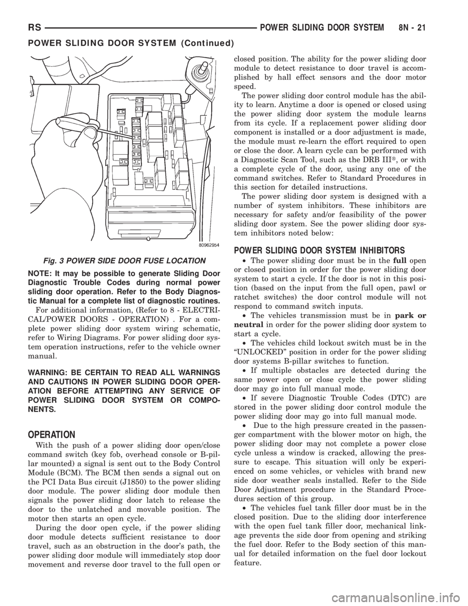
feature.Fig. 3 POWER SIDE DOOR FUSE LOCATION
RSPOWER SLIDING DOOR SYSTEM8N-21
POWER SLIDING DOOR SYSTEM (Continued)