2001 CHRYSLER VOYAGER engine coolant
[x] Cancel search: engine coolantPage 1849 of 4284
²Output Shaft Speed Sensor
Some examples ofindirect inputsto the TCM
are:
²Engine/Body Identification
²Manifold Pressure
²Target Idle
²Torque Reduction Confirmation
²Speed Control ON/OFF Switch
²Engine Coolant Temperature
²Ambient/Battery Temperature
²Brake Switch Status
²DRB Communication
Based on the information received from these var-
ious inputs, the TCM determines the appropriate
shift schedule and shift points, depending on the
present operating conditions and driver demand.
This is possible through the control of various direct
and indirect outputs.
Some examples of TCMdirect outputsare:
²Transmission Control Relay
²Solenoids (LR/CC, 2/4, OD and UD)
²Vehicle Speed (to PCM)
²Torque Reduction Request (to PCM)
An example of a TCMindirect outputis:
²Transmission Temperature (to PCM)
In addition to monitoring inputs and controlling
outputs, the TCM has other important responsibili-
ties and functions:
²Storing and maintaining Clutch Volume Indices
(CVI)
²Storing and selecting appropriate Shift Sched-
ules
²System self-diagnostics²Diagnostic capabilities (with DRB scan tool)
CLUTCH VOLUME INDEX (CVI)
An important function of the TCM is to monitor
Clutch Volume Index (CVI). CVIs represent the vol-
ume of fluid needed to compress a clutch pack.
The TCM monitors gear ratio changes by monitor-
ing the Input and Output Speed Sensors. The Input,
or Turbine Speed Sensor sends an electrical signal to
the TCM that represents input shaft rpm. The Out-
put Speed Sensor provides the TCM with output
shaft speed information.
By comparing the two inputs, the TCM can deter-
mine transaxle gear ratio. This is important to the
CVI calculation because the TCM determines CVIs
by monitoring how long it takes for a gear change to
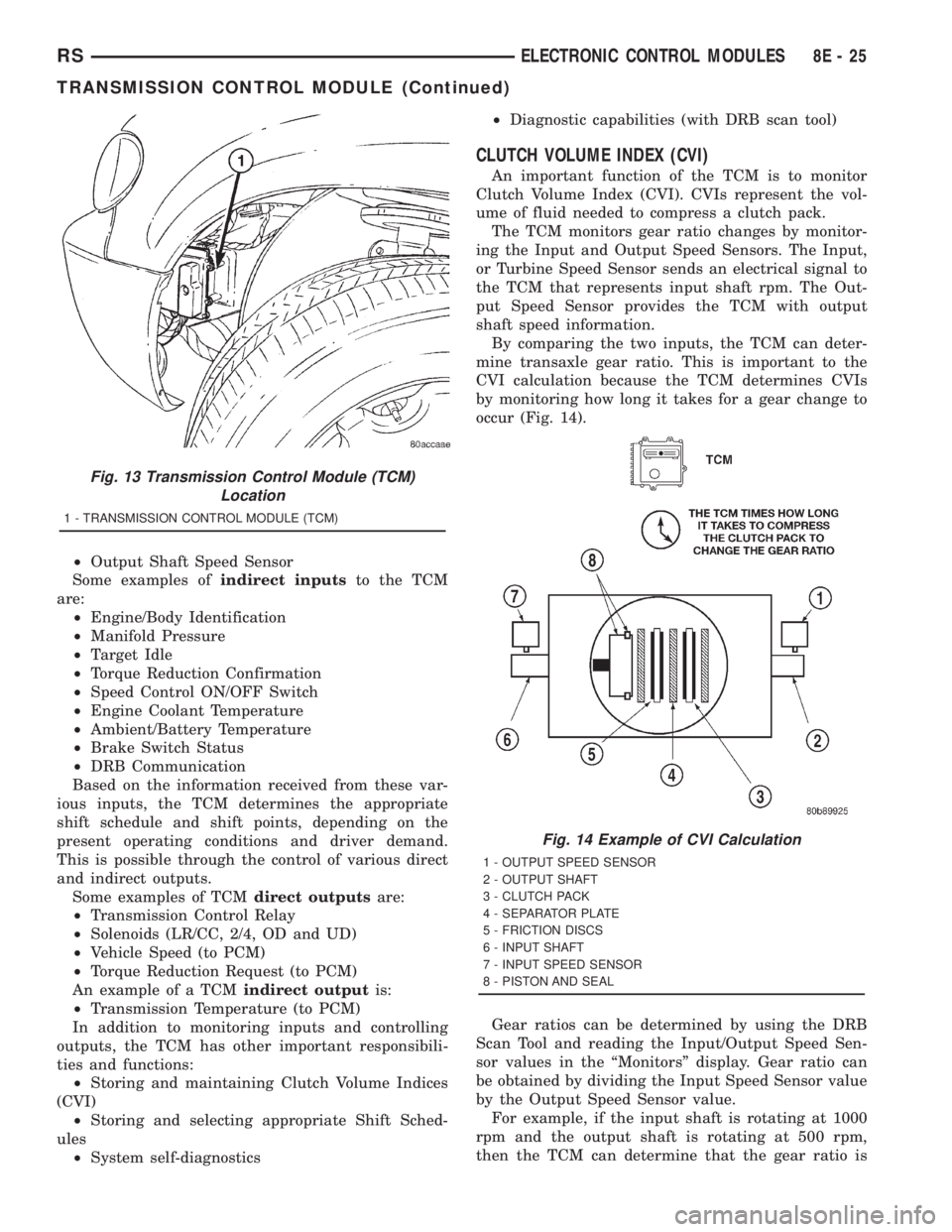
occur (Fig. 14).
Gear ratios can be determined by using the DRB
Scan Tool and reading the Input/Output Speed Sen-
sor values in the ªMonitorsº display. Gear ratio can
be obtained by dividing the Input Speed Sensor value
by the Output Speed Sensor value.
For example, if the input shaft is rotating at 1000
rpm and the output shaft is rotating at 500 rpm,
then the TCM can determine that the gear ratio is
Fig. 13 Transmission Control Module (TCM)
Location
1 - TRANSMISSION CONTROL MODULE (TCM)
Fig. 14 Example of CVI Calculation
1 - OUTPUT SPEED SENSOR
2 - OUTPUT SHAFT
3 - CLUTCH PACK
4 - SEPARATOR PLATE
5 - FRICTION DISCS
6 - INPUT SHAFT
7 - INPUT SPEED SENSOR
8 - PISTON AND SEAL
RSELECTRONIC CONTROL MODULES8E-25
TRANSMISSION CONTROL MODULE (Continued)
Page 1851 of 4284
Schedule Condition Expected Operation
HotOil temperature at start-up above
80É F± Normal operation (upshift,
kickdowns, and coastdowns)
± Full EMCC, no PEMCC except to
engage FEMCC (except at closed
throttle at speeds above 70-83 mph)
OverheatOil temperature above 240É F or
engine coolant temperature above
244É F± Delayed 2-3 upshift (25-32 mph)
± Delayed 3-4 upshift (41-48 mph)
± 3rd gear FEMCC from 30-48 mph
± 3rd gear PEMCC from 27-31 mph
Super OverheatOil temperature above 260É F ± All9Overheat9shift schedule
features apply
± 2nd gear PEMCC above 22 mph
± Above 22 mph the torque
converter will not unlock unless the
throttle is closed or if a wide open
throttle 2nd PEMCC to 1 kickdown
is made
STANDARD PROCEDURE - PINION FACTOR
SETTING
NOTE: This procedure must be performed if the
Transmission Control Module (TCM) has been
replaced with a NEW or replacement unit. Failure to
perform this procedure will result in an inoperative
or improperly calibrated speedometer.
The vehicle speed readings for the speedometer are
taken from the output speed sensor. The TCM must
be calibrated to the different combinations of equip-
ment (final drive and tires) available. Pinion Factor
allows the technician to set the Transmission Control
Module initial setting so that the speedometer read-
ings will be correct. To properly read and/or reset the
Pinion Factor, it is necessary to use a DRB scan tool.
(1) Plug the DRB scan tool into the diagnostic con-
nector located under the instrument panel.
(2) Select the Transmission menu.
(3) Select the Miscellaneous menu.
(4) Select Pinion Factor. Then follow the instruc-
tions on the DRB scan tool screen.
STANDARD PROCEDURE - QUICK LEARN
PROCEDURE
The quick learn procedure requires the use of the
DRB scan tool. This program allows the electronic
transaxle system to recalibrate itself. This will pro-
vide the best possible transaxle operation.NOTE: The quick learn procedure should be per-
formed if any of the following procedures are per-
formed:
²Transaxle Assembly Replacement
²Transmission Control Module Replacement
²Solenoid/Pressure Switch Assembly Replacement
²Clutch Plate and/or Seal Replacement
²Valve Body Replacement or Recondition
To perform the Quick Learn Procedure, the follow-
ing conditions must be met:
²The brakes must be applied
²The engine speed must be above 500 rpm
²The throttle angle (TPS) must be less than 3
degrees
²The shift lever position must stay until
prompted to shift to overdrive
²The shift lever position must stay in overdrive
after the Shift to Overdrive prompt until the DRB
indicates the procedure is complete
²The calculated oil temperature must be above
60É and below 200É
(1) Plug the DRB scan tool into the diagnostic con-
nector. The connector is located under the instrument
panel.
(2) Go to the Transmission screen.
(3) Go to the Miscellaneous screen.
(4) Select Quick Learn Procedure. Follow the
instructions of the DRB to perform the Quick Learn
Procedure.
RSELECTRONIC CONTROL MODULES8E-27
TRANSMISSION CONTROL MODULE (Continued)
Page 1875 of 4284
CHARGING
TABLE OF CONTENTS
page page
CHARGING
DESCRIPTION...........................21
OPERATION.............................21
DIAGNOSIS AND TESTING.................22
ON-BOARD DIAGNOSTIC SYSTEM.........22
SPECIFICATIONS........................22
SPECIAL TOOLS.........................23
BATTERY TEMPERATURE SENSOR
DESCRIPTION...........................23
OPERATION.............................23
REMOVAL..............................23
GENERATOR
DESCRIPTION...........................23
OPERATION.............................23REMOVAL..............................23
INSTALLATION...........................24
GENERATOR DECOUPLER PULLEY
DESCRIPTION...........................25
OPERATION.............................25
DIAGNOSIS AND TESTING.................25
GENERATOR DECOUPLER...............25
REMOVAL..............................25
INSTALLATION...........................26
VOLTAGE REGULATOR
DESCRIPTION...........................26
OPERATION.............................26
REMOVAL..............................26
CHARGING
DESCRIPTION - CHARGING SYSTEM
The charging system consists of:
²Generator
²Decoupler Pulley (If equipped)
²Electronic Voltage Regulator (EVR) circuitry
within the Powertrain Control Module (PCM)
²Ignition switch (refer to the Ignition System sec-
tion for information)
²Battery (refer to the Battery section for informa-
tion)
²Battery temperature sensor
²Voltmeter (refer to the Instrument Cluster sec-
tion for information)
²Wiring harness and connections (refer to the
Wiring section for information)
²Accessory drive belt (refer to the Cooling section
for more information)
OPERATION - CHARGING SYSTEM
The charging system is turned on and off with the
ignition switch. The system is on when the engine is
running and the ASD relay is energized. When the
ASD relay is on, voltage is supplied to the ASD relay
sense circuit at the PCM. This voltage is connected
through the PCM and supplied to one of the genera-
tor field terminals (Gen. Source +) at the back of the
generator.
The generator is driven by the engine through a
serpentine belt and pulley or decoupler pulley
arrangement.The amount of DC current produced by the gener-
ator is controlled by the EVR (field control) circuitry
contained within the PCM. This circuitry is con-
nected in series with the second rotor field terminal
and ground.
A battery temperature sensor is used to sense bat-
tery temperature. This temperature data, along with
data from monitored line voltage, is used by the PCM
to vary the battery charging rate. This is done by
cycling the ground path to control the strength of the
rotor magnetic field. The PCM then compensates and
regulates generator current output accordingly to
maintain system voltage at the targeted system volt-
age based on battery temperature.
All vehicles are equipped with On-Board Diagnos-
tics (OBD). All OBD-sensed systems, including EVR
(field control) circuitry, are monitored by the PCM.
Each monitored circuit is assigned a Diagnostic Trou-
ble Code (DTC). The PCM will store a DTC in elec-
tronic memory for certain failures it detects. Refer to
On-Board Diagnostics in the Electronic Control Mod-
ules(Refer to 8 - ELECTRICAL/ELECTRONIC CON-
TROL MODULES/POWERTRAIN CONTROL
MODULE - DESCRIPTION) section for more DTC
information.
The Check Gauges Lamp (if equipped) monitors:
charging system voltage,engine coolant tempera-
ture and engine oil pressure. If an extreme condition
is indicated, the lamp will be illuminated. This is
done as reminder to check the three gauges. The sig-
nal to activate the lamp is sent via the PCI bus cir-
cuits. The lamp is located on the instrument panel.
Refer to the Instrument Cluster section for additional
information.
RSCHARGING8F-21
Page 1927 of 4284
INSTRUMENT CLUSTER
TABLE OF CONTENTS
page page
INSTRUMENT CLUSTER
DESCRIPTION............................1
OPERATION.............................1
DIAGNOSIS AND TESTING..................1
INSTRUMENT CLUSTER..................1
REMOVAL..............................11
INSTALLATION...........................11
CLUSTER LENS
REMOVAL..............................12INSTALLATION...........................12
MECHANICAL TRANSMISSION RANGE
INDICATOR
REMOVAL..............................12
INSTALLATION...........................12
RED BRAKE WARNING INDICATOR
DESCRIPTION...........................12
OPERATION.............................12
INSTRUMENT CLUSTER
DESCRIPTION
The instrumentation gauges are contained in a
subdial assembly within the instrument cluster. The
individual gauges are not serviceable. If one of the
cluster gauges becomes faulty, the entire cluster
would require replacement.
The mechanical instrument cluster with a tachom-
eter is equipped with a electronic vacuum fluorescent
transmission range indicator (PRND3L), odometer,
and trip odometer display.
The mechanical instrument cluster without a
tachometer is equipped with a cable operated trans-
mission range indicator (PRND21) and a vacuum
flourescent odometer display.
The instrument cluster is equipped with the follow-
ing warning lamps.
²Lift Gate Ajar
²Low Fuel Level
²Low Windshield Washer Fluid Level
²Cruise
²Battery Voltage
²Fasten Seat Belt
²Door Ajar
²Headlamp Out
²Coolant Temperature
²Anti-Lock Brake
²Brake
²Airbag
²Traction Control
²Autostick
OPERATION
Refer to the vehicle Owner's Manual for operation
instructions and conditions for the Instrument Clus-
ter Gauges.
DIAGNOSIS AND TESTING - SELF-
DIAGNOSTICS
The instrument clusters are equipped with a self
diagnostic test feature to help identify electronic
problems. Prior to any test, perform the Self-Diag-
nostic Test. The self diagnostic system displays
instrument cluster stored fault codes in the odometer
display, sweeps the gauges to the calibration points,
and bulb checks the warning indicators. When the
key is in the ON position with the engine not run-
ning, the MIL will remain illuminated for regulatory
purposes.
To activate the Self-Diagnostic program:
(1) With the ignition switch in the OFF position,
depress the TRIP ODOMETER RESET button.
(2) Continue to hold the TRIP ODOMETER
RESET button untilSofand a number (software ver-
sion number (i.e.Sof 3.2) appears in the odometer
window (about five seconds) then release the button.
If a fault code is present, the cluster will display it in
the odometer display. When all fault codes have been
displayed, the cluster will displayªendºin the odom-
eter display. Refer to the table to determine what
each trouble code means.
RSINSTRUMENT CLUSTER8J-1
Page 1934 of 4284
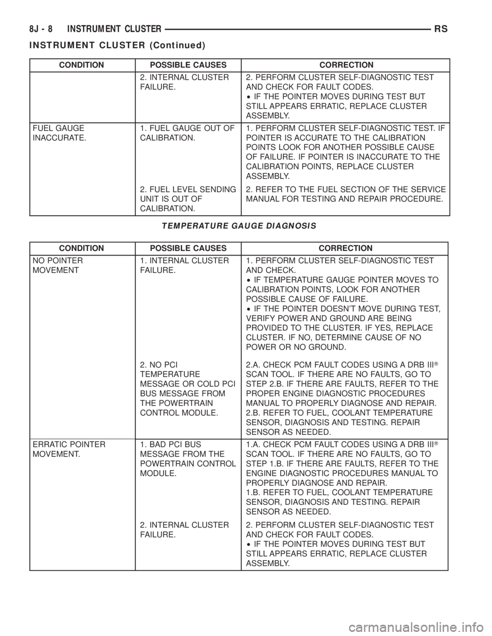
CONDITION POSSIBLE CAUSES CORRECTION
2. INTERNAL CLUSTER
FAILURE.2. PERFORM CLUSTER SELF-DIAGNOSTIC TEST
AND CHECK FOR FAULT CODES.
²IF THE POINTER MOVES DURING TEST BUT
STILL APPEARS ERRATIC, REPLACE CLUSTER
ASSEMBLY.
FUEL GAUGE
INACCURATE.1. FUEL GAUGE OUT OF
CALIBRATION.1. PERFORM CLUSTER SELF-DIAGNOSTIC TEST. IF
POINTER IS ACCURATE TO THE CALIBRATION
POINTS LOOK FOR ANOTHER POSSIBLE CAUSE
OF FAILURE. IF POINTER IS INACCURATE TO THE
CALIBRATION POINTS, REPLACE CLUSTER
ASSEMBLY.
2. FUEL LEVEL SENDING
UNIT IS OUT OF
CALIBRATION.2. REFER TO THE FUEL SECTION OF THE SERVICE
MANUAL FOR TESTING AND REPAIR PROCEDURE.
TEMPERATURE GAUGE DIAGNOSIS
CONDITION POSSIBLE CAUSES CORRECTION
NO POINTER
MOVEMENT1. INTERNAL CLUSTER
FAILURE.1. PERFORM CLUSTER SELF-DIAGNOSTIC TEST
AND CHECK.
²IF TEMPERATURE GAUGE POINTER MOVES TO
CALIBRATION POINTS, LOOK FOR ANOTHER
POSSIBLE CAUSE OF FAILURE.
²IF THE POINTER DOESN'T MOVE DURING TEST,
VERIFY POWER AND GROUND ARE BEING
PROVIDED TO THE CLUSTER. IF YES, REPLACE
CLUSTER. IF NO, DETERMINE CAUSE OF NO
POWER OR NO GROUND.
2. NO PCI
TEMPERATURE
MESSAGE OR COLD PCI
BUS MESSAGE FROM
THE POWERTRAIN
CONTROL MODULE.2.A. CHECK PCM FAULT CODES USING A DRB IIIT
SCAN TOOL. IF THERE ARE NO FAULTS, GO TO
STEP 2.B. IF THERE ARE FAULTS, REFER TO THE
PROPER ENGINE DIAGNOSTIC PROCEDURES
MANUAL TO PROPERLY DIAGNOSE AND REPAIR.
2.B. REFER TO FUEL, COOLANT TEMPERATURE
SENSOR, DIAGNOSIS AND TESTING. REPAIR
SENSOR AS NEEDED.
ERRATIC POINTER
MOVEMENT.1. BAD PCI BUS
MESSAGE FROM THE
POWERTRAIN CONTROL
MODULE.1.A. CHECK PCM FAULT CODES USING A DRB IIIT
SCAN TOOL. IF THERE ARE NO FAULTS, GO TO
STEP 1.B. IF THERE ARE FAULTS, REFER TO THE
ENGINE DIAGNOSTIC PROCEDURES MANUAL TO
PROPERLY DIAGNOSE AND REPAIR.
1.B. REFER TO FUEL, COOLANT TEMPERATURE
SENSOR, DIAGNOSIS AND TESTING. REPAIR
SENSOR AS NEEDED.
2. INTERNAL CLUSTER
FAILURE.2. PERFORM CLUSTER SELF-DIAGNOSTIC TEST
AND CHECK FOR FAULT CODES.
²IF THE POINTER MOVES DURING TEST BUT
STILL APPEARS ERRATIC, REPLACE CLUSTER
ASSEMBLY.
8J - 8 INSTRUMENT CLUSTERRS
INSTRUMENT CLUSTER (Continued)
Page 2099 of 4284
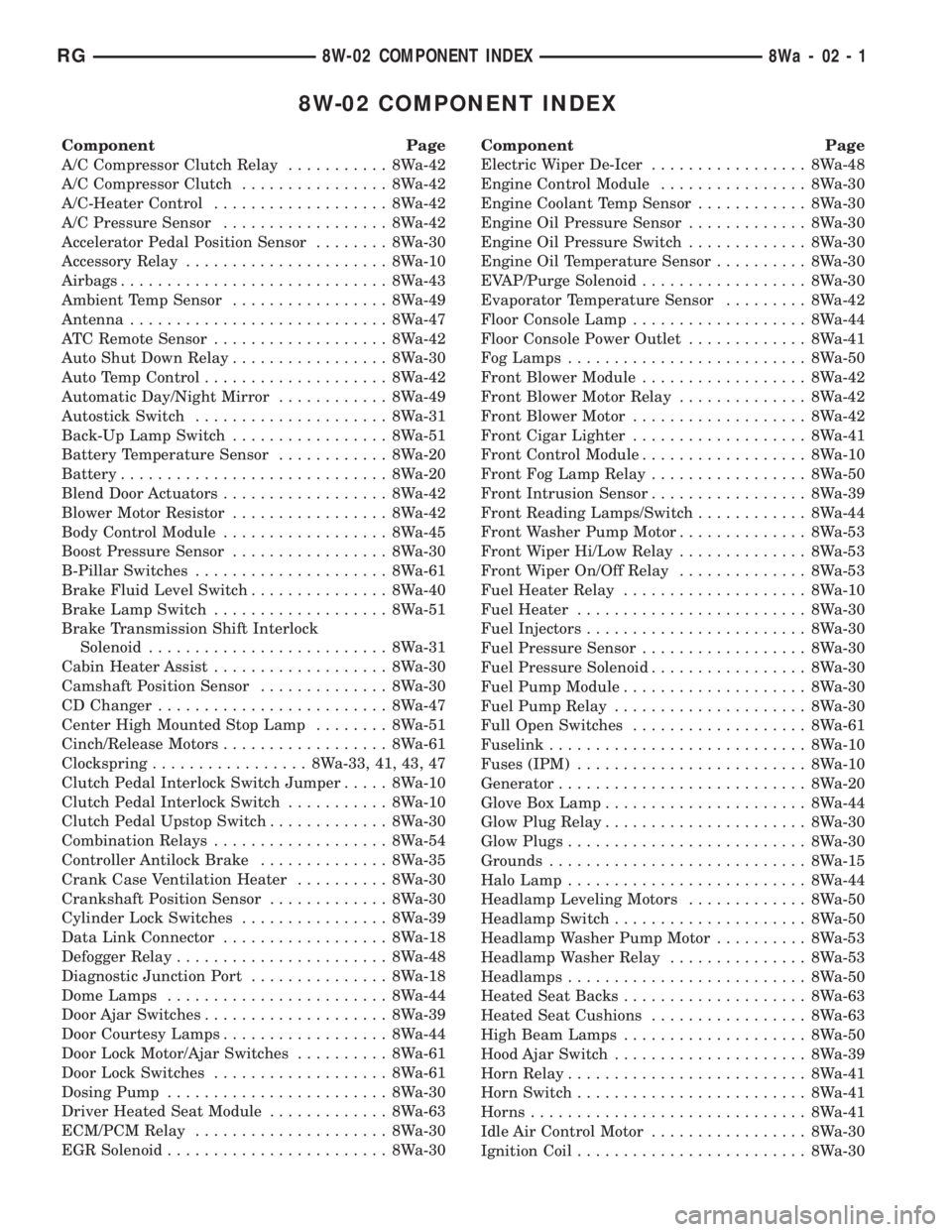
8W-02 COMPONENT INDEX
Component Page
A/C Compressor Clutch Relay........... 8Wa-42
A/C Compressor Clutch................ 8Wa-42
A/C-Heater Control................... 8Wa-42
A/C Pressure Sensor.................. 8Wa-42
Accelerator Pedal Position Sensor........ 8Wa-30
Accessory Relay...................... 8Wa-10
Airbags............................. 8Wa-43
Ambient Temp Sensor................. 8Wa-49
Antenna............................ 8Wa-47
ATC Remote Sensor................... 8Wa-42
Auto Shut Down Relay................. 8Wa-30
Auto Temp Control.................... 8Wa-42
Automatic Day/Night Mirror............ 8Wa-49
Autostick Switch..................... 8Wa-31
Back-Up Lamp Switch................. 8Wa-51
Battery Temperature Sensor............ 8Wa-20
Battery............................. 8Wa-20
Blend Door Actuators.................. 8Wa-42
Blower Motor Resistor................. 8Wa-42
Body Control Module.................. 8Wa-45
Boost Pressure Sensor................. 8Wa-30
B-Pillar Switches..................... 8Wa-61
Brake Fluid Level Switch............... 8Wa-40
Brake Lamp Switch................... 8Wa-51
Brake Transmission Shift Interlock
Solenoid.......................... 8Wa-31
Cabin Heater Assist................... 8Wa-30
Camshaft Position Sensor.............. 8Wa-30
CD Changer......................... 8Wa-47
Center High Mounted Stop Lamp........ 8Wa-51
Cinch/Release Motors.................. 8Wa-61
Clockspring................. 8Wa-33, 41, 43, 47
Clutch Pedal Interlock Switch Jumper..... 8Wa-10
Clutch Pedal Interlock Switch........... 8Wa-10
Clutch Pedal Upstop Switch............. 8Wa-30
Combination Relays................... 8Wa-54
Controller Antilock Brake.............. 8Wa-35
Crank Case Ventilation Heater.......... 8Wa-30
Crankshaft Position Sensor............. 8Wa-30
Cylinder Lock Switches................ 8Wa-39
Data Link Connector.................. 8Wa-18
Defogger Relay....................... 8Wa-48
Diagnostic Junction Port............... 8Wa-18
Dome Lamps........................ 8Wa-44
Door Ajar Switches.................... 8Wa-39
Door Courtesy Lamps.................. 8Wa-44
Door Lock Motor/Ajar Switches.......... 8Wa-61
Door Lock Switches................... 8Wa-61
Dosing Pump........................ 8Wa-30
Driver Heated Seat Module............. 8Wa-63
ECM/PCM Relay..................... 8Wa-30
EGR Solenoid........................ 8Wa-30Component Page
Electric Wiper De-Icer................. 8Wa-48
Engine Control Module................ 8Wa-30
Engine Coolant Temp Sensor............ 8Wa-30
Engine Oil Pressure Sensor............. 8Wa-30
Engine Oil Pressure Switch............. 8Wa-30
Engine Oil Temperature Sensor.......... 8Wa-30
EVAP/Purge Solenoid.................. 8Wa-30
Evaporator Temperature Sensor......... 8Wa-42
Floor Console Lamp................... 8Wa-44
Floor Console Power Outlet............. 8Wa-41
Fog Lamps.......................... 8Wa-50
Front Blower Module.................. 8Wa-42
Front Blower Motor Relay.............. 8Wa-42
Front Blower Motor................... 8Wa-42
Front Cigar Lighter................... 8Wa-41
Front Control Module.................. 8Wa-10
Front Fog Lamp Relay................. 8Wa-50
Front Intrusion Sensor................. 8Wa-39
Front Reading Lamps/Switch............ 8Wa-44
Front Washer Pump Motor.............. 8Wa-53
Front Wiper Hi/Low Relay.............. 8Wa-53
Front Wiper On/Off Relay.............. 8Wa-53
Fuel Heater Relay.................... 8Wa-10
Fuel Heater......................... 8Wa-30
Fuel Injectors........................ 8Wa-30
Fuel Pressure Sensor.................. 8Wa-30
Fuel Pressure Solenoid................. 8Wa-30
Fuel Pump Module.................... 8Wa-30
Fuel Pump Relay..................... 8Wa-30
Full Open Switches................... 8Wa-61
Fuselink............................ 8Wa-10
Fuses (IPM)......................... 8Wa-10
Generator........................... 8Wa-20
Glove Box Lamp...................... 8Wa-44
Glow Plug Relay...................... 8Wa-30
Glow Plugs.......................... 8Wa-30
Grounds............................ 8Wa-15
Halo Lamp.......................... 8Wa-44
Headlamp Leveling Motors............. 8Wa-50
Headlamp Switch..................... 8Wa-50
Headlamp Washer Pump Motor.......... 8Wa-53
Headlamp Washer Relay............... 8Wa-53
Headlamps.......................... 8Wa-50
Heated Seat Backs.................... 8Wa-63
Heated Seat Cushions................. 8Wa-63
High Beam Lamps.................... 8Wa-50
Hood Ajar Switch..................... 8Wa-39
Horn Relay.......................... 8Wa-41
Horn Switch......................... 8Wa-41
Horns.............................. 8Wa-41
Idle Air Control Motor................. 8Wa-30
Ignition Coil......................... 8Wa-30
RG8W-02 COMPONENT INDEX8Wa-02-1
Page 2203 of 4284
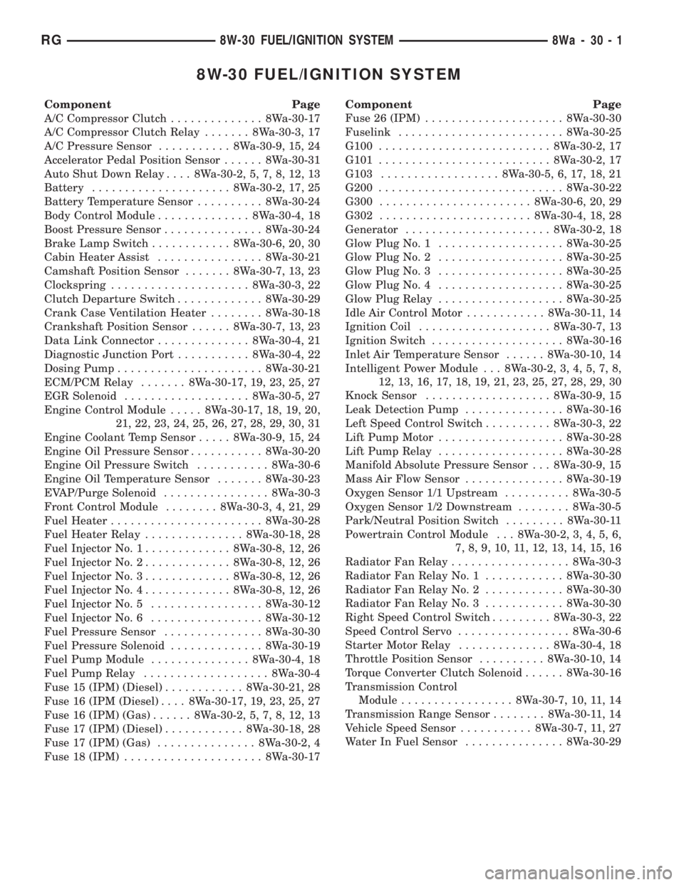
8W-30 FUEL/IGNITION SYSTEM
Component Page
A/C Compressor Clutch.............. 8Wa-30-17
A/C Compressor Clutch Relay....... 8Wa-30-3, 17
A/C Pressure Sensor........... 8Wa-30-9, 15, 24
Accelerator Pedal Position Sensor...... 8Wa-30-31
Auto Shut Down Relay.... 8Wa-30-2, 5, 7, 8, 12, 13
Battery..................... 8Wa-30-2, 17, 25
Battery Temperature Sensor.......... 8Wa-30-24
Body Control Module.............. 8Wa-30-4, 18
Boost Pressure Sensor............... 8Wa-30-24
Brake Lamp Switch............ 8Wa-30-6, 20, 30
Cabin Heater Assist................ 8Wa-30-21
Camshaft Position Sensor....... 8Wa-30-7, 13, 23
Clockspring..................... 8Wa-30-3, 22
Clutch Departure Switch............. 8Wa-30-29
Crank Case Ventilation Heater........ 8Wa-30-18
Crankshaft Position Sensor...... 8Wa-30-7, 13, 23
Data Link Connector.............. 8Wa-30-4, 21
Diagnostic Junction Port........... 8Wa-30-4, 22
Dosing Pump...................... 8Wa-30-21
ECM/PCM Relay....... 8Wa-30-17, 19, 23, 25, 27
EGR Solenoid................... 8Wa-30-5, 27
Engine Control Module..... 8Wa-30-17, 18, 19, 20,
21, 22, 23, 24, 25, 26, 27, 28, 29, 30, 31
Engine Coolant Temp Sensor..... 8Wa-30-9, 15, 24
Engine Oil Pressure Sensor........... 8Wa-30-20
Engine Oil Pressure Switch........... 8Wa-30-6
Engine Oil Temperature Sensor....... 8Wa-30-23
EVAP/Purge Solenoid................ 8Wa-30-3
Front Control Module........ 8Wa-30-3, 4, 21, 29
Fuel Heater....................... 8Wa-30-28
Fuel Heater Relay............... 8Wa-30-18, 28
Fuel Injector No. 1............. 8Wa-30-8, 12, 26
Fuel Injector No. 2............. 8Wa-30-8, 12, 26
Fuel Injector No. 3............. 8Wa-30-8, 12, 26
Fuel Injector No. 4............. 8Wa-30-8, 12, 26
Fuel Injector No. 5................. 8Wa-30-12
Fuel Injector No. 6................. 8Wa-30-12
Fuel Pressure Sensor............... 8Wa-30-30
Fuel Pressure Solenoid.............. 8Wa-30-19
Fuel Pump Module............... 8Wa-30-4, 18
Fuel Pump Relay................... 8Wa-30-4
Fuse 15 (IPM) (Diesel)............ 8Wa-30-21, 28
Fuse 16 (IPM (Diesel).... 8Wa-30-17, 19, 23, 25, 27
Fuse 16 (IPM) (Gas)...... 8Wa-30-2, 5, 7, 8, 12, 13
Fuse 17 (IPM) (Diesel)............ 8Wa-30-18, 28
Fuse 17 (IPM) (Gas)............... 8Wa-30-2, 4
Fuse 18 (IPM)..................... 8Wa-30-17Component Page
Fuse 26 (IPM)..................... 8Wa-30-30
Fuselink......................... 8Wa-30-25
G100.......................... 8Wa-30-2, 17
G101.......................... 8Wa-30-2, 17
G103.................. 8Wa-30-5, 6, 17, 18, 21
G200............................ 8Wa-30-22
G300....................... 8Wa-30-6, 20, 29
G302....................... 8Wa-30-4, 18, 28
Generator...................... 8Wa-30-2, 18
Glow Plug No. 1................... 8Wa-30-25
Glow Plug No. 2................... 8Wa-30-25
Glow Plug No. 3................... 8Wa-30-25
Glow Plug No. 4................... 8Wa-30-25
Glow Plug Relay................... 8Wa-30-25
Idle Air Control Motor............ 8Wa-30-11, 14
Ignition Coil.................... 8Wa-30-7, 13
Ignition Switch.................... 8Wa-30-16
Inlet Air Temperature Sensor...... 8Wa-30-10, 14
Intelligent Power Module . . . 8Wa-30-2, 3, 4, 5, 7, 8,
12, 13, 16, 17, 18, 19, 21, 23, 25, 27, 28, 29, 30
Knock Sensor................... 8Wa-30-9, 15
Leak Detection Pump............... 8Wa-30-16
Left Speed Control Switch.......... 8Wa-30-3, 22
Lift Pump Motor................... 8Wa-30-28
Lift Pump Relay................... 8Wa-30-28
Manifold Absolute Pressure Sensor . . . 8Wa-30-9, 15
Mass Air Flow Sensor............... 8Wa-30-19
Oxygen Sensor 1/1 Upstream.......... 8Wa-30-5
Oxygen Sensor 1/2 Downstream........ 8Wa-30-5
Park/Neutral Position Switch......... 8Wa-30-11
Powertrain Control Module . . . 8Wa-30-2, 3, 4, 5, 6,
7, 8, 9, 10, 11, 12, 13, 14, 15, 16
Radiator Fan Relay.................. 8Wa-30-3
Radiator Fan Relay No. 1............ 8Wa-30-30
Radiator Fan Relay No. 2............ 8Wa-30-30
Radiator Fan Relay No. 3............ 8Wa-30-30
Right Speed Control Switch......... 8Wa-30-3, 22
Speed Control Servo................. 8Wa-30-6
Starter Motor Relay.............. 8Wa-30-4, 18
Throttle Position Sensor.......... 8Wa-30-10, 14
Torque Converter Clutch Solenoid...... 8Wa-30-16
Transmission Control
Module................. 8Wa-30-7, 10, 11, 14
Transmission Range Sensor........ 8Wa-30-11, 14
Vehicle Speed Sensor........... 8Wa-30-7, 11, 27
Water In Fuel Sensor............... 8Wa-30-29
RG8W-30 FUEL/IGNITION SYSTEM8Wa-30-1
Page 2269 of 4284
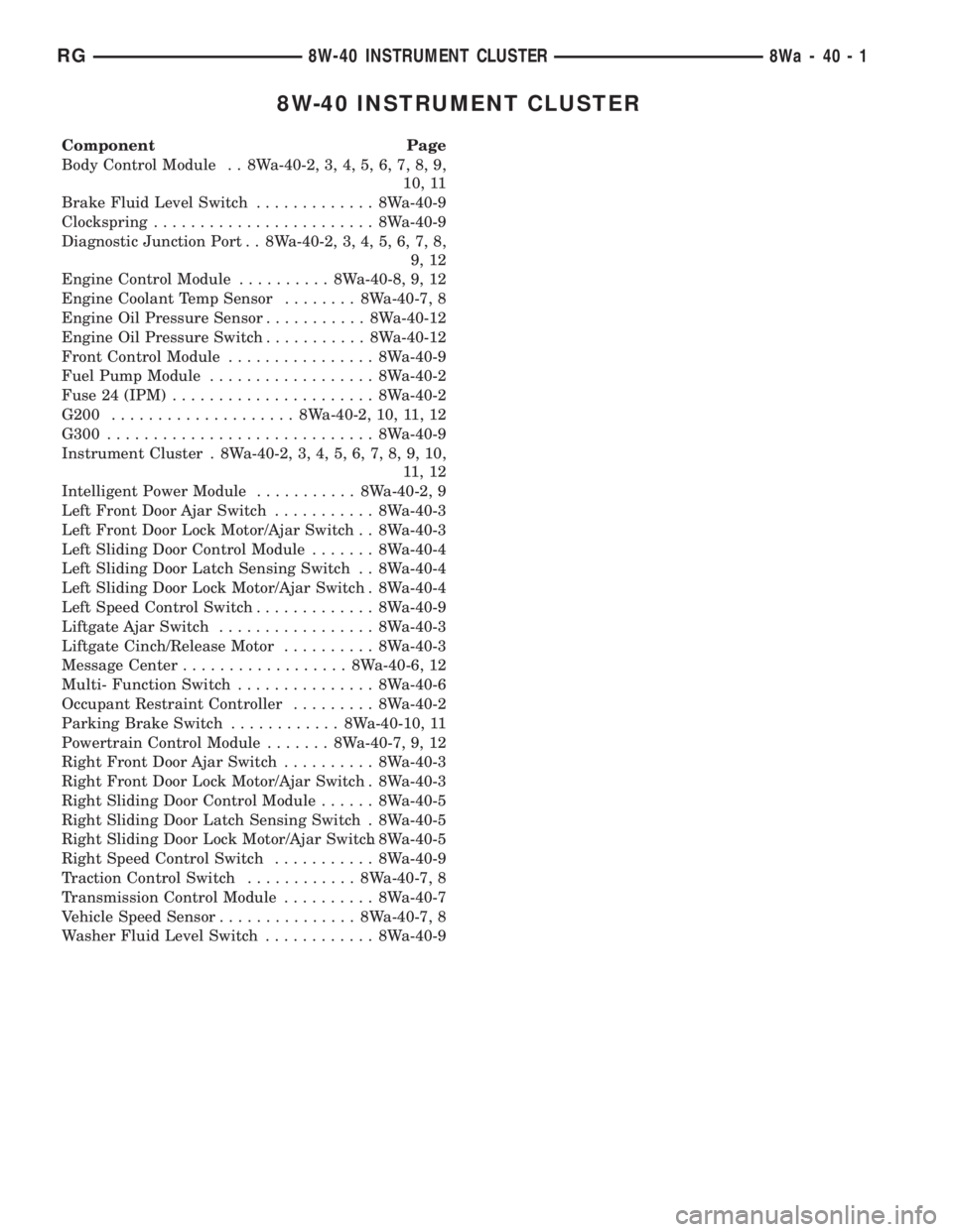
8W-40 INSTRUMENT CLUSTER
Component Page
Body Control Module . . 8Wa-40-2, 3, 4, 5, 6, 7, 8, 9,
10, 11
Brake Fluid Level Switch............. 8Wa-40-9
Clockspring........................ 8Wa-40-9
Diagnostic Junction Port . . 8Wa-40-2, 3, 4, 5, 6, 7, 8,
9, 12
Engine Control Module.......... 8Wa-40-8, 9, 12
Engine Coolant Temp Sensor........ 8Wa-40-7, 8
Engine Oil Pressure Sensor........... 8Wa-40-12
Engine Oil Pressure Switch........... 8Wa-40-12
Front Control Module................ 8Wa-40-9
Fuel Pump Module.................. 8Wa-40-2
Fuse 24 (IPM)...................... 8Wa-40-2
G200.................... 8Wa-40-2, 10, 11, 12
G300............................. 8Wa-40-9
Instrument Cluster . 8Wa-40-2, 3, 4, 5, 6, 7, 8, 9, 10,
11 , 1 2
Intelligent Power Module........... 8Wa-40-2, 9
Left Front Door Ajar Switch........... 8Wa-40-3
Left Front Door Lock Motor/Ajar Switch . . 8Wa-40-3
Left Sliding Door Control Module....... 8Wa-40-4
Left Sliding Door Latch Sensing Switch . . 8Wa-40-4
Left Sliding Door Lock Motor/Ajar Switch . 8Wa-40-4
Left Speed Control Switch............. 8Wa-40-9
Liftgate Ajar Switch................. 8Wa-40-3
Liftgate Cinch/Release Motor.......... 8Wa-40-3
Message Center.................. 8Wa-40-6, 12
Multi- Function Switch............... 8Wa-40-6
Occupant Restraint Controller......... 8Wa-40-2
Parking Brake Switch............ 8Wa-40-10, 11
Powertrain Control Module....... 8Wa-40-7, 9, 12
Right Front Door Ajar Switch.......... 8Wa-40-3
Right Front Door Lock Motor/Ajar Switch . 8Wa-40-3
Right Sliding Door Control Module...... 8Wa-40-5
Right Sliding Door Latch Sensing Switch . 8Wa-40-5
Right Sliding Door Lock Motor/Ajar Switch. 8Wa-40-5
Right Speed Control Switch........... 8Wa-40-9
Traction Control Switch............ 8Wa-40-7, 8
Transmission Control Module.......... 8Wa-40-7
Vehicle Speed Sensor............... 8Wa-40-7, 8
Washer Fluid Level Switch............ 8Wa-40-9
RG8W-40 INSTRUMENT CLUSTER8Wa-40-1