2001 CHRYSLER VOYAGER engine coolant
[x] Cancel search: engine coolantPage 2718 of 4284
CYLINDER HEAD
DESCRIPTION
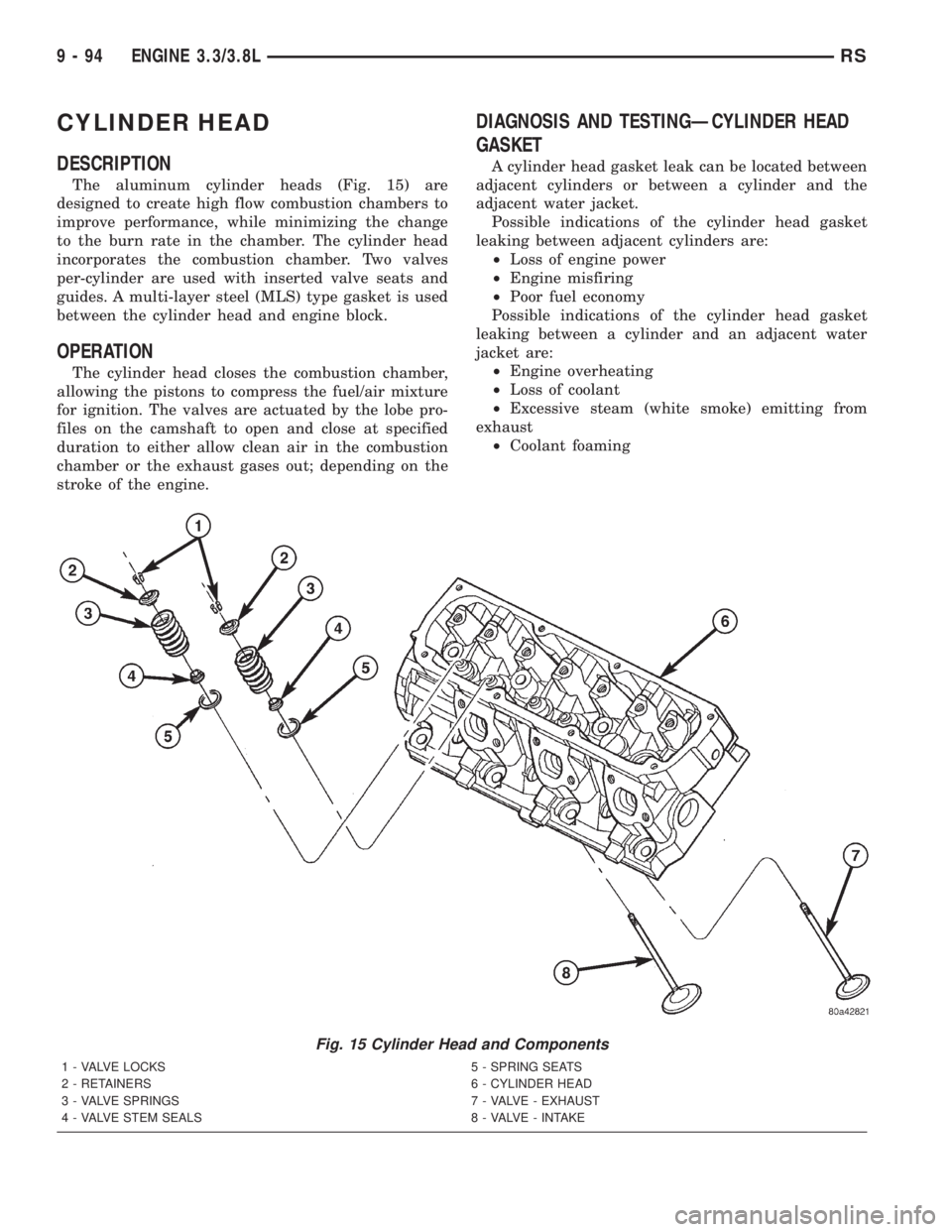
The aluminum cylinder heads (Fig. 15) are
designed to create high flow combustion chambers to
improve performance, while minimizing the change
to the burn rate in the chamber. The cylinder head
incorporates the combustion chamber. Two valves
per-cylinder are used with inserted valve seats and
guides. A multi-layer steel (MLS) type gasket is used
between the cylinder head and engine block.
OPERATION
The cylinder head closes the combustion chamber,
allowing the pistons to compress the fuel/air mixture
for ignition. The valves are actuated by the lobe pro-
files on the camshaft to open and close at specified
duration to either allow clean air in the combustion
chamber or the exhaust gases out; depending on the
stroke of the engine.
DIAGNOSIS AND TESTINGÐCYLINDER HEAD
GASKET
A cylinder head gasket leak can be located between
adjacent cylinders or between a cylinder and the
adjacent water jacket.
Possible indications of the cylinder head gasket
leaking between adjacent cylinders are:
²Loss of engine power
²Engine misfiring
²Poor fuel economy
Possible indications of the cylinder head gasket
leaking between a cylinder and an adjacent water
jacket are:
²Engine overheating
²Loss of coolant
²Excessive steam (white smoke) emitting from
exhaust
²Coolant foaming
Fig. 15 Cylinder Head and Components
1 - VALVE LOCKS 5 - SPRING SEATS
2 - RETAINERS 6 - CYLINDER HEAD
3 - VALVE SPRINGS 7 - VALVE - EXHAUST
4 - VALVE STEM SEALS 8 - VALVE - INTAKE
9 - 94 ENGINE 3.3/3.8LRS
Page 2719 of 4284
CYLINDER-TO-CYLINDER LEAKAGE TEST
To determine if an engine cylinder head gasket is
leaking between adjacent cylinders, follow the proce-
dures in Cylinder Compression Pressure Test (Refer
to 9 - ENGINE - DIAGNOSIS AND TESTING). An
engine cylinder head gasket leaking between adja-
cent cylinders will result in approximately a 50±70%
reduction in compression pressure.
CYLINDER-TO-WATER JACKET LEAKAGE TEST
WARNING: USE EXTREME CAUTION WHEN THE
ENGINE IS OPERATING WITH COOLANT PRES-
SURE CAP REMOVED.
VISUAL TEST METHOD
With the engine cool, remove the coolant pressure
cap. Start the engine and allow it to warm up until
thermostat opens.
If a large combustion/compression pressure leak
exists, bubbles will be visible in the coolant.
COOLING SYSTEM TESTER METHOD
WARNING: WITH COOLING SYSTEM TESTER IN
PLACE, PRESSURE WILL BUILD UP FAST. EXCES-
SIVE PRESSURE BUILT UP, BY CONTINUOUS
ENGINE OPERATION, MUST BE RELEASED TO A
SAFE PRESSURE POINT. NEVER PERMIT PRES-
SURE TO EXCEED 138 kPa (20 psi).
Install Cooling System Tester 7700 or equivalent to
pressure cap neck. Start the engine and observe the
tester's pressure gauge. If gauge pulsates with every
power stroke of a cylinder a combustion pressure
leak is evident.
CHEMICAL TEST METHOD
Combustion leaks into the cooling system can also
be checked by using Bloc-Chek Kit C-3685-A or
equivalent. Perform test following the procedures
supplied with the tool kit.
REMOVAL - CYLINDER HEAD
(1) Drain the cooling system. (Refer to 7 - COOL-
ING - STANDARD PROCEDURE)
(2) Disconnect negative cable from battery.
(3) Remove upper and lower intake manifolds.
(Refer to 9 - ENGINE/MANIFOLDS/INTAKE MANI-
FOLD - REMOVAL)
WARNING: INTAKE MANIFOLD GASKET IS MADE
OF VERY THIN METAL AND MAY CAUSE PER-
SONAL INJURY, HANDLE WITH CARE.(4) Remove the cylinder head covers. (Refer to 9 -
ENGINE/CYLINDER HEAD/CYLINDER HEAD
COVER(S) - REMOVAL)
(5) Remove the spark plugs from cylinder head.
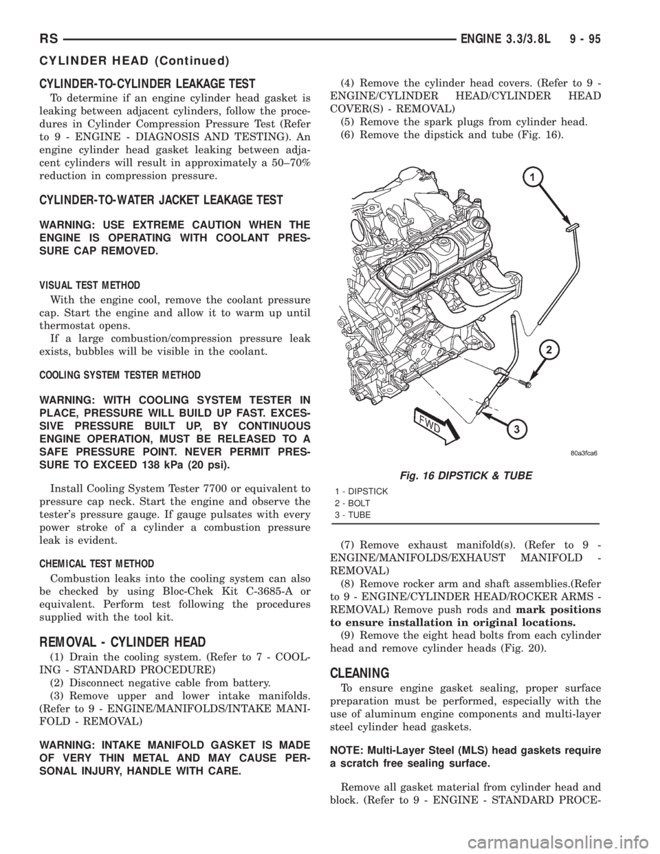
(6) Remove the dipstick and tube (Fig. 16).
(7) Remove exhaust manifold(s). (Refer to 9 -
ENGINE/MANIFOLDS/EXHAUST MANIFOLD -
REMOVAL)
(8) Remove rocker arm and shaft assemblies.(Refer
to 9 - ENGINE/CYLINDER HEAD/ROCKER ARMS -
REMOVAL) Remove push rods andmark positions
to ensure installation in original locations.
(9) Remove the eight head bolts from each cylinder
head and remove cylinder heads (Fig. 20).
CLEANING
To ensure engine gasket sealing, proper surface
preparation must be performed, especially with the
use of aluminum engine components and multi-layer
steel cylinder head gaskets.
NOTE: Multi-Layer Steel (MLS) head gaskets require
a scratch free sealing surface.
Remove all gasket material from cylinder head and
block. (Refer to 9 - ENGINE - STANDARD PROCE-
Fig. 16 DIPSTICK & TUBE
1 - DIPSTICK
2 - BOLT
3 - TUBE
RSENGINE 3.3/3.8L9-95
CYLINDER HEAD (Continued)
Page 2758 of 4284
OIL COOLER & LINES
DESCRIPTION
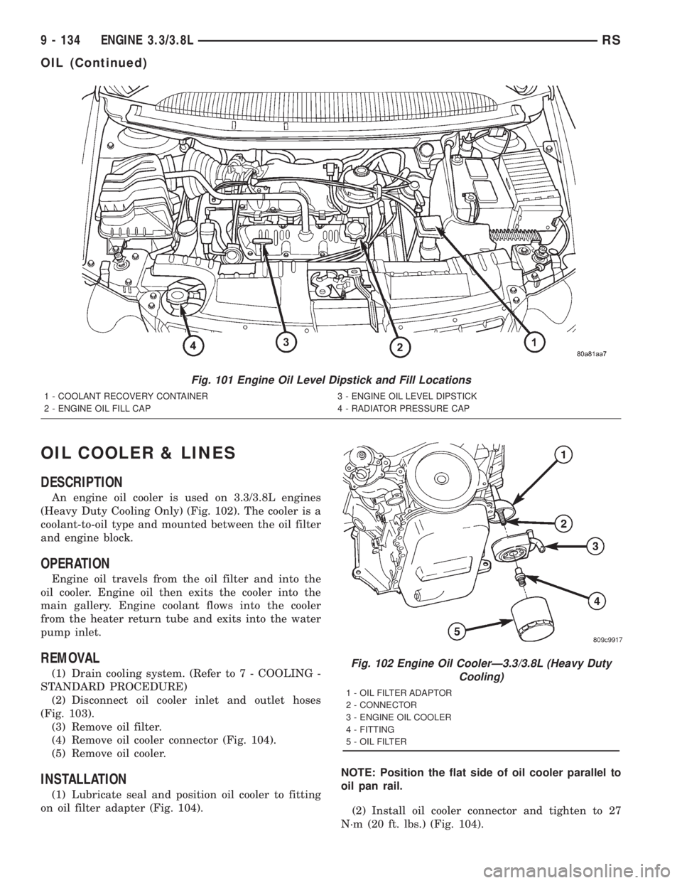
An engine oil cooler is used on 3.3/3.8L engines
(Heavy Duty Cooling Only) (Fig. 102). The cooler is a
coolant-to-oil type and mounted between the oil filter
and engine block.
OPERATION
Engine oil travels from the oil filter and into the
oil cooler. Engine oil then exits the cooler into the
main gallery. Engine coolant flows into the cooler
from the heater return tube and exits into the water
pump inlet.
REMOVAL
(1) Drain cooling system. (Refer to 7 - COOLING -
STANDARD PROCEDURE)
(2) Disconnect oil cooler inlet and outlet hoses
(Fig. 103).
(3) Remove oil filter.
(4) Remove oil cooler connector (Fig. 104).
(5) Remove oil cooler.
INSTALLATION
(1) Lubricate seal and position oil cooler to fitting
on oil filter adapter (Fig. 104).NOTE: Position the flat side of oil cooler parallel to
oil pan rail.
(2) Install oil cooler connector and tighten to 27
N´m (20 ft. lbs.) (Fig. 104).
Fig. 101 Engine Oil Level Dipstick and Fill Locations
1 - COOLANT RECOVERY CONTAINER 3 - ENGINE OIL LEVEL DIPSTICK
2 - ENGINE OIL FILL CAP 4 - RADIATOR PRESSURE CAP
Fig. 102 Engine Oil CoolerÐ3.3/3.8L (Heavy Duty
Cooling)
1 - OIL FILTER ADAPTOR
2 - CONNECTOR
3 - ENGINE OIL COOLER
4 - FITTING
5 - OIL FILTER
9 - 134 ENGINE 3.3/3.8LRS
OIL (Continued)
Page 2764 of 4284
(8) Remove oil pressure relief valve. (Refer to 9 -
ENGINE/LUBRICATION/OIL PRESSURE RELIEF
VALVE - REMOVAL)
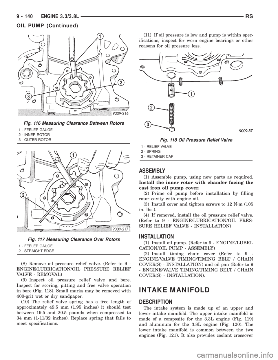
(9) Inspect oil pressure relief valve and bore.
Inspect for scoring, pitting and free valve operation
in bore (Fig. 118). Small marks may be removed with
400-grit wet or dry sandpaper.
(10) The relief valve spring has a free length of
approximately 49.5 mm (1.95 inches) it should test
between 19.5 and 20.5 pounds when compressed to
34 mm (1-11/32 inches). Replace spring that fails to
meet specifications.(11) If oil pressure is low and pump is within spec-
ifications, inspect for worn engine bearings or other
reasons for oil pressure loss.
ASSEMBLY
(1) Assemble pump, using new parts as required.
Install the inner rotor with chamfer facing the
cast iron oil pump cover.
(2) Prime oil pump before installation by filling
rotor cavity with engine oil.
(3) Install cover and tighten screws to 12 N´m (105
in. lbs.).
(4) If removed, install the oil pressure relief valve.
(Refer to 9 - ENGINE/LUBRICATION/OIL PRES-
SURE RELIEF VALVE - INSTALLATION)
INSTALLATION
(1) Install oil pump. (Refer to 9 - ENGINE/LUBRI-
CATION/OIL PUMP - ASSEMBLY)
(2) Install timing chain cover (Refer to 9 -
ENGINE/VALVE TIMING/TIMING BELT / CHAIN
COVER(S) - INSTALLATION) and oil pan (Refer to 9
- ENGINE/VALVE TIMING/TIMING BELT / CHAIN
COVER(S) - INSTALLATION).
INTAKE MANIFOLD
DESCRIPTION
The intake system is made up of an upper and
lower intake manifold. The upper intake manifold is
made of a composite for the 3.3L engine (Fig. 119)
and aluminum for the 3.8L engine (Fig. 120). The
lower intake manifold is common between the two
engines (Fig. 121). It also provides coolant crossover
Fig. 116 Measuring Clearance Between Rotors
1 - FEELER GAUGE
2 - INNER ROTOR
3 - OUTER ROTOR
Fig. 117 Measuring Clearance Over Rotors
1 - FEELER GAUGE
2 - STRAIGHT EDGE
Fig. 118 Oil Pressure Relief Valve
1 - RELIEF VALVE
2 - SPRING
3 - RETAINER CAP
9 - 140 ENGINE 3.3/3.8LRS
OIL PUMP (Continued)
Page 2765 of 4284
between cylinder heads and houses the coolant ther-
mostat (Fig. 121).
The intake manifold utilizes a compact design with
very low restriction and outstanding flow balance.
This design allows the engine to perform with a wide
torque curve while increasing higher rpm horse-
power.
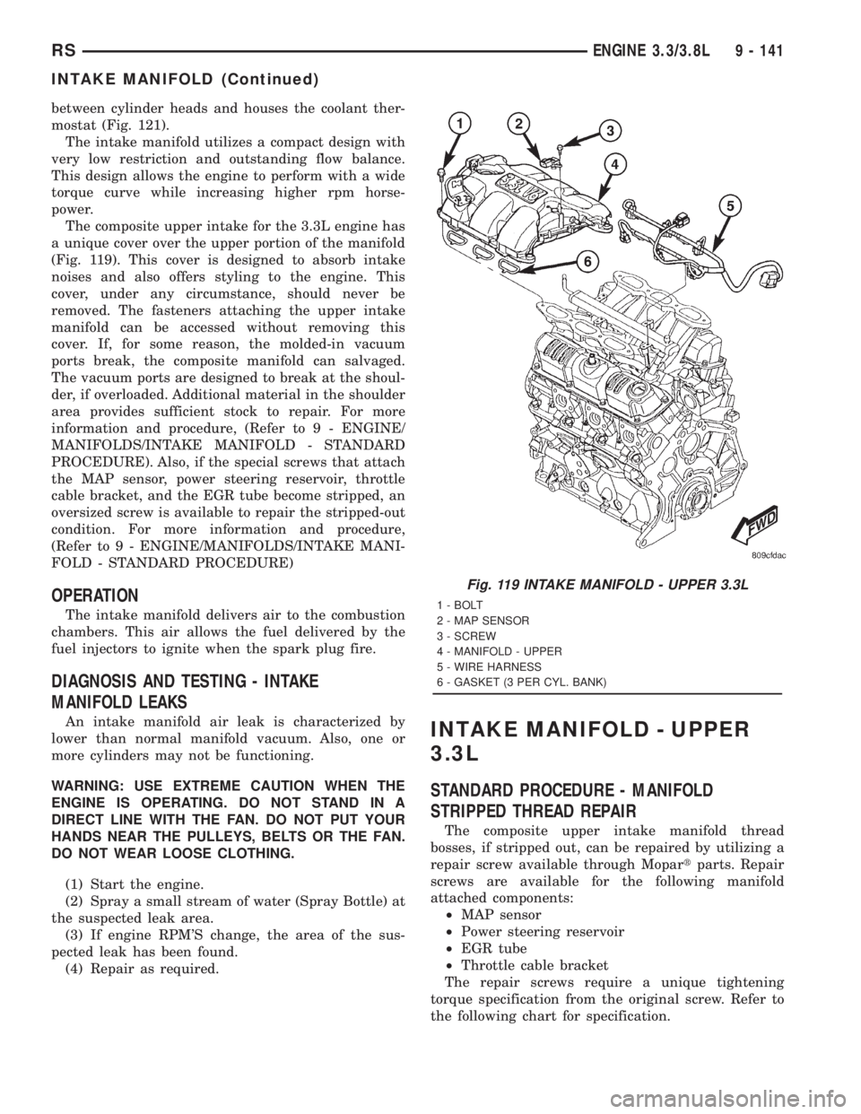
The composite upper intake for the 3.3L engine has
a unique cover over the upper portion of the manifold
(Fig. 119). This cover is designed to absorb intake
noises and also offers styling to the engine. This
cover, under any circumstance, should never be
removed. The fasteners attaching the upper intake
manifold can be accessed without removing this
cover. If, for some reason, the molded-in vacuum
ports break, the composite manifold can salvaged.
The vacuum ports are designed to break at the shoul-
der, if overloaded. Additional material in the shoulder
area provides sufficient stock to repair. For more
information and procedure, (Refer to 9 - ENGINE/
MANIFOLDS/INTAKE MANIFOLD - STANDARD
PROCEDURE). Also, if the special screws that attach
the MAP sensor, power steering reservoir, throttle
cable bracket, and the EGR tube become stripped, an
oversized screw is available to repair the stripped-out
condition. For more information and procedure,
(Refer to 9 - ENGINE/MANIFOLDS/INTAKE MANI-
FOLD - STANDARD PROCEDURE)
OPERATION
The intake manifold delivers air to the combustion
chambers. This air allows the fuel delivered by the
fuel injectors to ignite when the spark plug fire.
DIAGNOSIS AND TESTING - INTAKE
MANIFOLD LEAKS
An intake manifold air leak is characterized by
lower than normal manifold vacuum. Also, one or
more cylinders may not be functioning.
WARNING: USE EXTREME CAUTION WHEN THE
ENGINE IS OPERATING. DO NOT STAND IN A
DIRECT LINE WITH THE FAN. DO NOT PUT YOUR
HANDS NEAR THE PULLEYS, BELTS OR THE FAN.
DO NOT WEAR LOOSE CLOTHING.
(1) Start the engine.
(2) Spray a small stream of water (Spray Bottle) at
the suspected leak area.
(3) If engine RPM'S change, the area of the sus-
pected leak has been found.
(4) Repair as required.INTAKE MANIFOLD - UPPER
3.3L
STANDARD PROCEDURE - MANIFOLD
STRIPPED THREAD REPAIR
The composite upper intake manifold thread
bosses, if stripped out, can be repaired by utilizing a
repair screw available through Mopartparts. Repair
screws are available for the following manifold
attached components:
²MAP sensor
²Power steering reservoir
²EGR tube
²Throttle cable bracket
The repair screws require a unique tightening
torque specification from the original screw. Refer to
the following chart for specification.
Fig. 119 INTAKE MANIFOLD - UPPER 3.3L
1 - BOLT
2 - MAP SENSOR
3 - SCREW
4 - MANIFOLD - UPPER
5 - WIRE HARNESS
6 - GASKET (3 PER CYL. BANK)
RSENGINE 3.3/3.8L9 - 141
INTAKE MANIFOLD (Continued)
Page 2773 of 4284
INSTALLATION
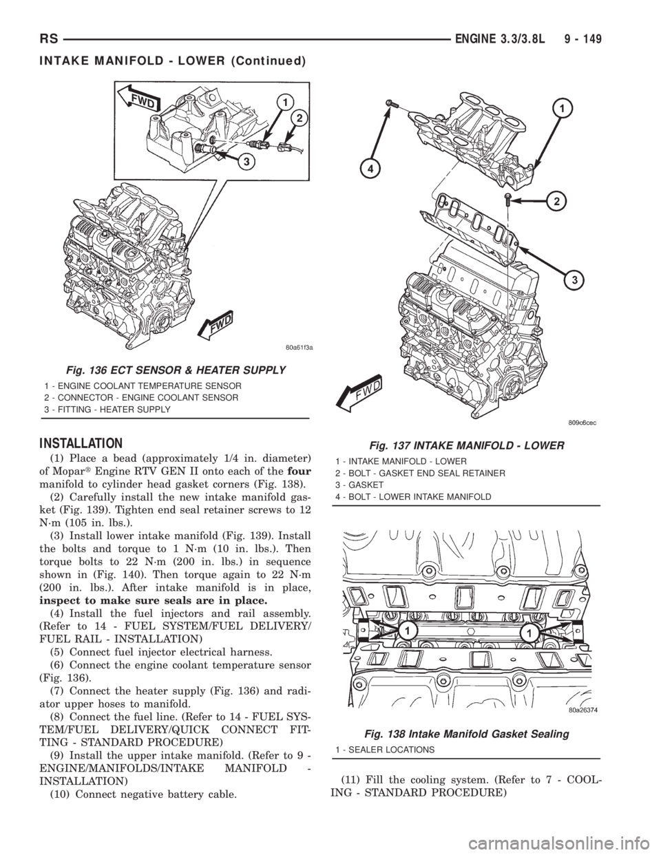
(1) Place a bead (approximately 1/4 in. diameter)
of MopartEngine RTV GEN II onto each of thefour
manifold to cylinder head gasket corners (Fig. 138).
(2) Carefully install the new intake manifold gas-
ket (Fig. 139). Tighten end seal retainer screws to 12
N´m (105 in. lbs.).
(3) Install lower intake manifold (Fig. 139). Install
the bolts and torque to 1 N´m (10 in. lbs.). Then
torque bolts to 22 N´m (200 in. lbs.) in sequence
shown in (Fig. 140). Then torque again to 22 N´m
(200 in. lbs.). After intake manifold is in place,
inspect to make sure seals are in place.
(4) Install the fuel injectors and rail assembly.
(Refer to 14 - FUEL SYSTEM/FUEL DELIVERY/
FUEL RAIL - INSTALLATION)
(5) Connect fuel injector electrical harness.
(6) Connect the engine coolant temperature sensor
(Fig. 136).
(7) Connect the heater supply (Fig. 136) and radi-
ator upper hoses to manifold.
(8) Connect the fuel line. (Refer to 14 - FUEL SYS-
TEM/FUEL DELIVERY/QUICK CONNECT FIT-
TING - STANDARD PROCEDURE)
(9) Install the upper intake manifold. (Refer to 9 -
ENGINE/MANIFOLDS/INTAKE MANIFOLD -
INSTALLATION)
(10) Connect negative battery cable.(11) Fill the cooling system. (Refer to 7 - COOL-
ING - STANDARD PROCEDURE)
Fig. 136 ECT SENSOR & HEATER SUPPLY
1 - ENGINE COOLANT TEMPERATURE SENSOR
2 - CONNECTOR - ENGINE COOLANT SENSOR
3 - FITTING - HEATER SUPPLY
Fig. 137 INTAKE MANIFOLD - LOWER
1 - INTAKE MANIFOLD - LOWER
2 - BOLT - GASKET END SEAL RETAINER
3 - GASKET
4 - BOLT - LOWER INTAKE MANIFOLD
Fig. 138 Intake Manifold Gasket Sealing
1 - SEALER LOCATIONS
RSENGINE 3.3/3.8L9 - 149
INTAKE MANIFOLD - LOWER (Continued)
Page 2785 of 4284
DESCRIPTION - ENGINE COVER
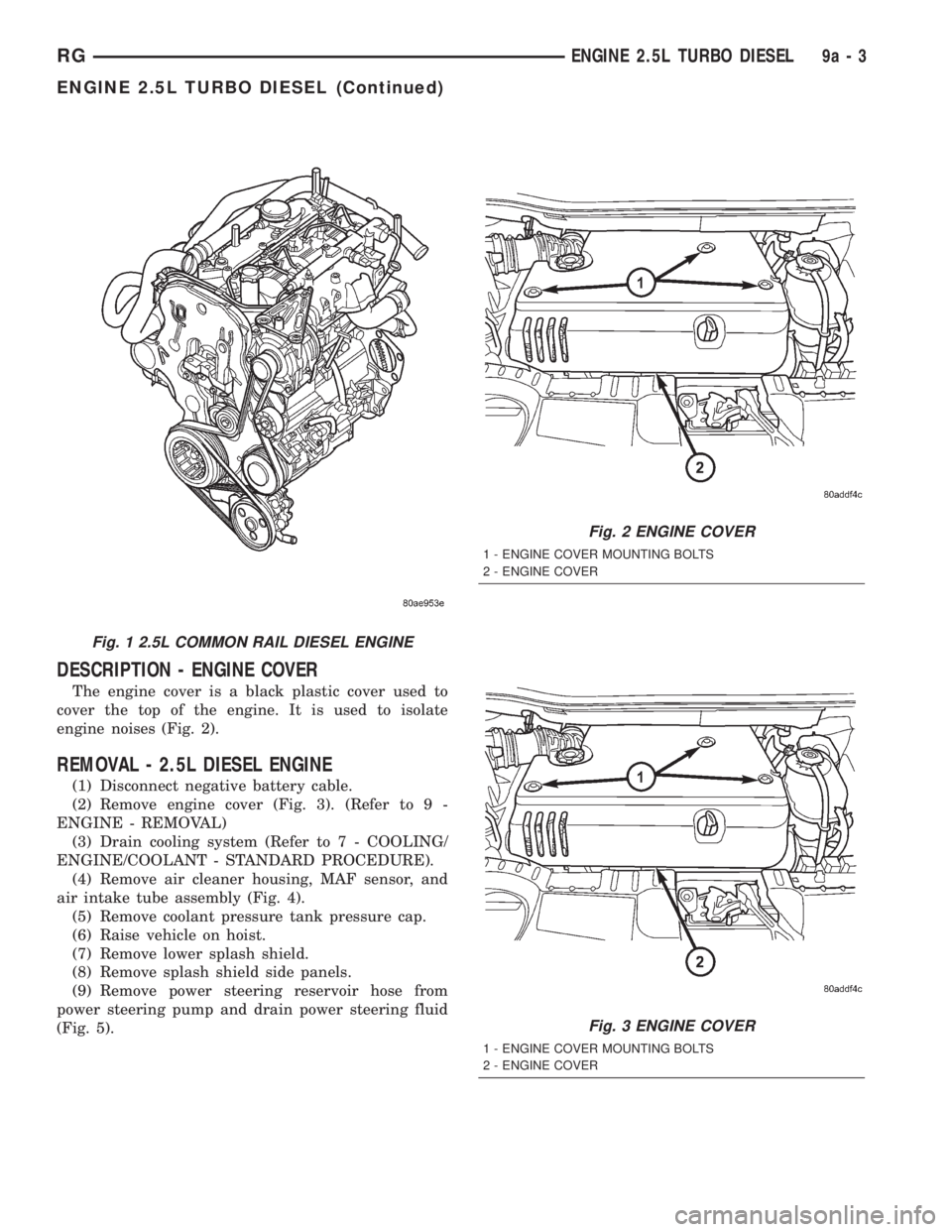
The engine cover is a black plastic cover used to
cover the top of the engine. It is used to isolate
engine noises (Fig. 2).
REMOVAL - 2.5L DIESEL ENGINE
(1) Disconnect negative battery cable.
(2) Remove engine cover (Fig. 3). (Refer to 9 -
ENGINE - REMOVAL)
(3) Drain cooling system (Refer to 7 - COOLING/
ENGINE/COOLANT - STANDARD PROCEDURE).
(4) Remove air cleaner housing, MAF sensor, and
air intake tube assembly (Fig. 4).
(5) Remove coolant pressure tank pressure cap.
(6) Raise vehicle on hoist.
(7) Remove lower splash shield.
(8) Remove splash shield side panels.
(9) Remove power steering reservoir hose from
power steering pump and drain power steering fluid
(Fig. 5).
Fig. 1 2.5L COMMON RAIL DIESEL ENGINE
Fig. 2 ENGINE COVER
1 - ENGINE COVER MOUNTING BOLTS
2 - ENGINE COVER
Fig. 3 ENGINE COVER
1 - ENGINE COVER MOUNTING BOLTS
2 - ENGINE COVER
RGENGINE 2.5L TURBO DIESEL9a-3
ENGINE 2.5L TURBO DIESEL (Continued)
Page 2786 of 4284
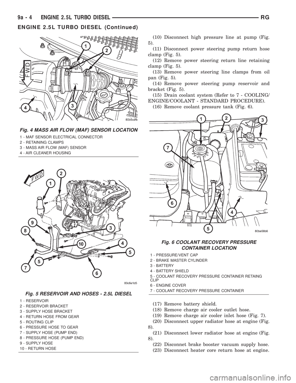
(10) Disconnect high pressure line at pump (Fig.
5).
(11) Disconnect power steering pump return hose
clamp (Fig. 5).
(12) Remove power steering return line retaining
clamp (Fig. 5).
(13) Remove power steering line clamps from oil
pan (Fig. 5).
(14) Remove power steering pump reservoir and
bracket (Fig. 5).
(15) Drain coolant system (Refer to 7 - COOLING/
ENGINE/COOLANT - STANDARD PROCEDURE).
(16) Remove coolant pressure tank (Fig. 6).
(17) Remove battery shield.
(18) Remove charge air cooler outlet hose.
(19) Remove charge air cooler inlet hose (Fig. 7).
(20) Disconnect upper radiator hose at engine (Fig.
8).
(21) Disconnect lower radiator hose at engine (Fig.
8).
(22) Disconnet brake booster vacuum supply hose.
(23) Disconnect heater core return hose at engine.
Fig. 4 MASS AIR FLOW (MAF) SENSOR LOCATION
1 - MAF SENSOR ELECTRICAL CONNECTOR
2 - RETAINING CLAMPS
3 - MASS AIR FLOW (MAF) SENSOR
4 - AIR CLEANER HOUSING
Fig. 5 RESERVOIR AND HOSES - 2.5L DIESEL
1 - RESERVOIR
2 - RESERVOIR BRACKET
3 - SUPPLY HOSE BRACKET
4 - RETURN HOSE FROM GEAR
5 - ROUTING CLIP
6 - PRESSURE HOSE TO GEAR
7 - SUPPLY HOSE (PUMP END)
8 - PRESSURE HOSE (PUMP END)
9 - SUPPLY HOSE
10 - RETURN HOSE
Fig. 6 COOLANT RECOVERY PRESSURE
CONTAINER LOCATION
1 - PRESSURE/VENT CAP
2 - BRAKE MASTER CYLINDER
3 - BATTERY
4 - BATTERY SHIELD
5 - COOLANT RECOVERY PRESSURE CONTAINER RETAING
CLIP
6 - ENGINE COVER
7 - COOLANT RECOVERY PRESSURE CONTAINER
9a - 4 ENGINE 2.5L TURBO DIESELRG
ENGINE 2.5L TURBO DIESEL (Continued)