Page 3577 of 4770

EM04Y±03
S05048
± ENGINE MECHANICAL (1MZ±FE)ENGINE UNIT
EM±71
1357 Author�: Date�:
REMOVAL
1. REMOVE BATTERY AND TRAY
2. REMOVE HOOD
3. REMOVE ENGINE FENDER APRON SEALS
4. DRAIN ENGINE COOLANT
5. DRAIN ENGINE OIL
6. DISCONNECT ACCELERATOR CABLE
7. REMOVE AIR CLEANER CAP ASSEMBLY AND AIR
CLEANER CASE
8. REMOVE CRUISE CONTROL ACTUATOR
9. REMOVE RADIATOR (See page CO±18)
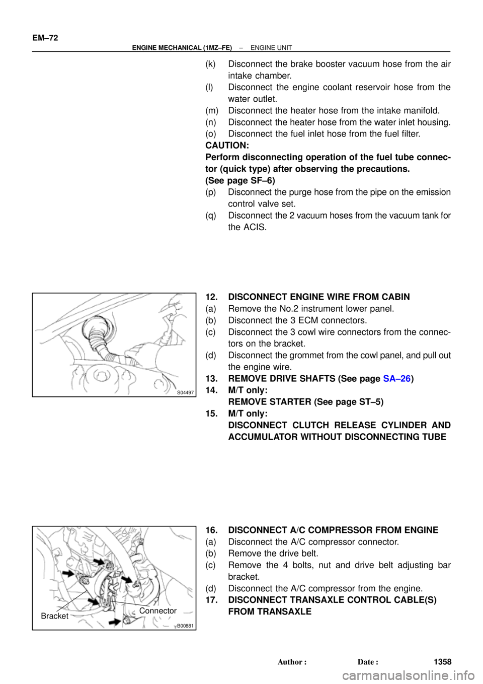
10. REMOVE FRONT EXHAUST PIPE
(a) Remove the 2 bolts holding the support stay to the sup-
port bracket.
(b) Remove the 2 bolts holding the support bracket to the
front frame.
(c) Remove the 2 bolts and 2 nuts holding the front exhaust
pipe to the center exhaust pipe.
(d) Remove the 4 nuts holding the front exhaust pipe to the
exhaust manifolds.
(e) Remove the front exhaust pipe and 3 gaskets.
11. DISCONNECT CONNECTORS, CABLE, CLAMPS
AND HOSES
(a) Disconnect the igniter connector on the LH fender apron.
(b) Disconnect the noise filter connector on the LH fender
apron.
(c) Disconnect the generator wire and connector.
(d) Disconnect the starter wire and connector.
(e) Disconnect the 2 ground strap connectors from the LH
fender apron.
(f) Disconnect the 2 ground strap connectors from the RH
fender apron.
(g) Disconnect the ground cable from the battery body brack-
et.
(h) Disconnect the engine wire protector clamp from the bat-
tery body bracket.
(i) Disconnect the engine wire clamp from the bracket on the
RH fender apron.
(j) Disconnect the engine wire clamp from the bracket on the
fuel filter.
Page 3578 of 4770

S04497
B00881
Connector
Bracket
EM±72
± ENGINE MECHANICAL (1MZ±FE)ENGINE UNIT
1358 Author�: Date�:
(k) Disconnect the brake booster vacuum hose from the air
intake chamber.
(l) Disconnect the engine coolant reservoir hose from the
water outlet.
(m) Disconnect the heater hose from the intake manifold.
(n) Disconnect the heater hose from the water inlet housing.
(o) Disconnect the fuel inlet hose from the fuel filter.
CAUTION:
Perform disconnecting operation of the fuel tube connec-
tor (quick type) after observing the precautions.
(See page SF±6)
(p) Disconnect the purge hose from the pipe on the emission
control valve set.
(q) Disconnect the 2 vacuum hoses from the vacuum tank for
the ACIS.
12. DISCONNECT ENGINE WIRE FROM CABIN
(a) Remove the No.2 instrument lower panel.
(b) Disconnect the 3 ECM connectors.
(c) Disconnect the 3 cowl wire connectors from the connec-
tors on the bracket.
(d) Disconnect the grommet from the cowl panel, and pull out
the engine wire.
13. REMOVE DRIVE SHAFTS (See page SA±26)
14. M/T only:
REMOVE STARTER (See page ST±5)
15. M/T only:
DISCONNECT CLUTCH RELEASE CYLINDER AND
ACCUMULATOR WITHOUT DISCONNECTING TUBE
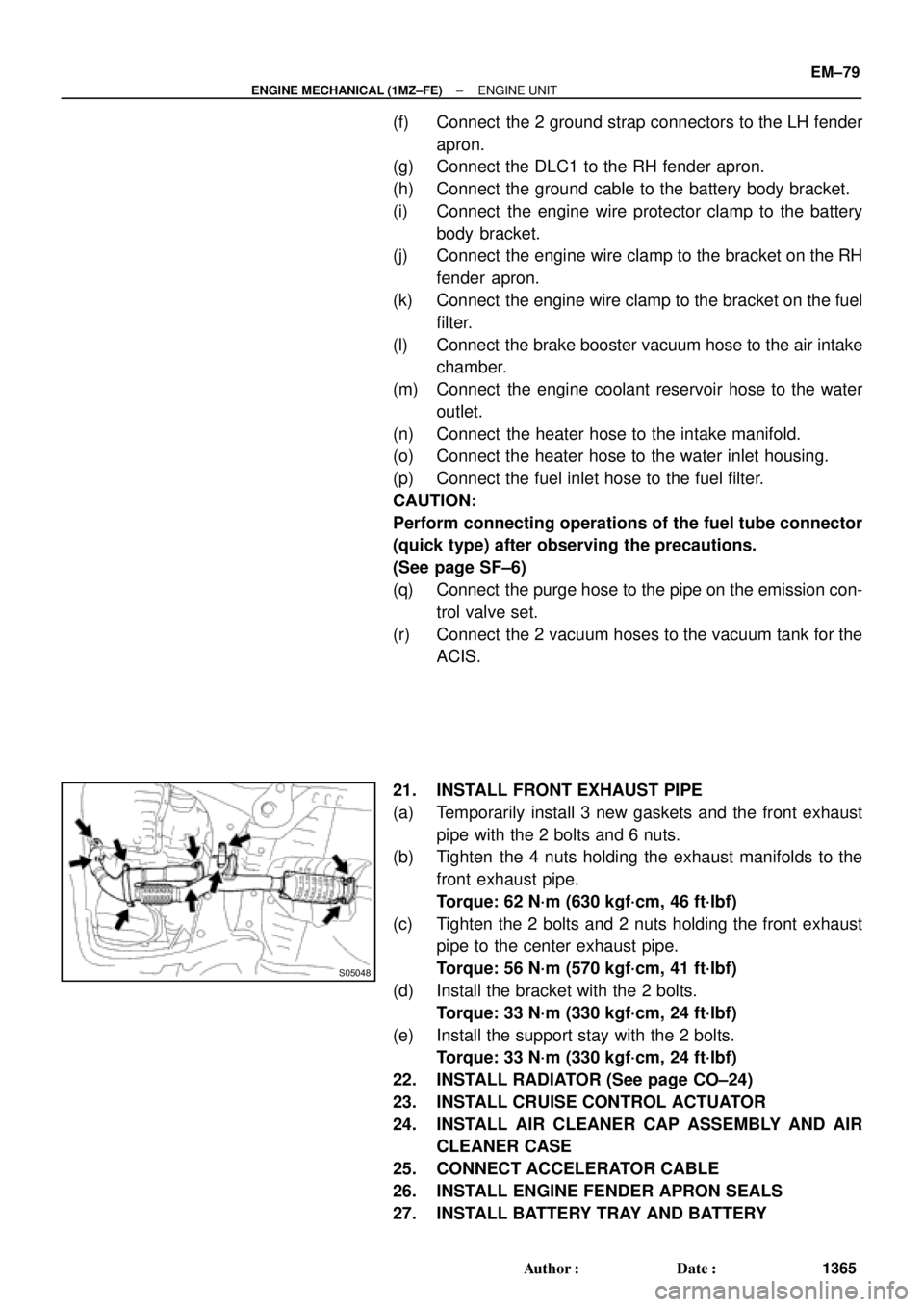
16. DISCONNECT A/C COMPRESSOR FROM ENGINE
(a) Disconnect the A/C compressor connector.
(b) Remove the drive belt.
(c) Remove the 4 bolts, nut and drive belt adjusting bar
bracket.
(d) Disconnect the A/C compressor from the engine.
17. DISCONNECT TRANSAXLE CONTROL CABLE(S)
FROM TRANSAXLE
Page 3585 of 4770

S05048
± ENGINE MECHANICAL (1MZ±FE)ENGINE UNIT
EM±79
1365 Author�: Date�:
(f) Connect the 2 ground strap connectors to the LH fender
apron.
(g) Connect the DLC1 to the RH fender apron.
(h) Connect the ground cable to the battery body bracket.
(i) Connect the engine wire protector clamp to the battery
body bracket.
(j) Connect the engine wire clamp to the bracket on the RH
fender apron.
(k) Connect the engine wire clamp to the bracket on the fuel
filter.
(l) Connect the brake booster vacuum hose to the air intake
chamber.
(m) Connect the engine coolant reservoir hose to the water
outlet.
(n) Connect the heater hose to the intake manifold.
(o) Connect the heater hose to the water inlet housing.
(p) Connect the fuel inlet hose to the fuel filter.
CAUTION:
Perform connecting operations of the fuel tube connector
(quick type) after observing the precautions.
(See page SF±6)
(q) Connect the purge hose to the pipe on the emission con-
trol valve set.
(r) Connect the 2 vacuum hoses to the vacuum tank for the
ACIS.
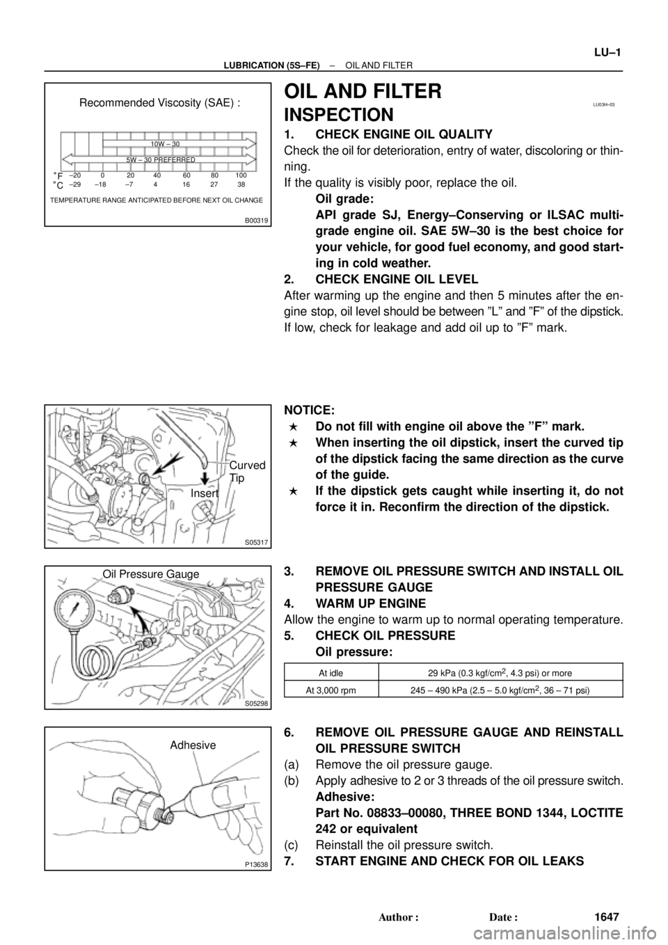
21. INSTALL FRONT EXHAUST PIPE
(a) Temporarily install 3 new gaskets and the front exhaust
pipe with the 2 bolts and 6 nuts.
(b) Tighten the 4 nuts holding the exhaust manifolds to the
front exhaust pipe.
Torque: 62 N´m (630 kgf´cm, 46 ft´lbf)
(c) Tighten the 2 bolts and 2 nuts holding the front exhaust
pipe to the center exhaust pipe.
Torque: 56 N´m (570 kgf´cm, 41 ft´lbf)
(d) Install the bracket with the 2 bolts.
Torque: 33 N´m (330 kgf´cm, 24 ft´lbf)
(e) Install the support stay with the 2 bolts.
Torque: 33 N´m (330 kgf´cm, 24 ft´lbf)
22. INSTALL RADIATOR (See page CO±24)
23. INSTALL CRUISE CONTROL ACTUATOR
24. INSTALL AIR CLEANER CAP ASSEMBLY AND AIR
CLEANER CASE
25. CONNECT ACCELERATOR CABLE
26. INSTALL ENGINE FENDER APRON SEALS
27. INSTALL BATTERY TRAY AND BATTERY
Page 3713 of 4770

IN±42
± INTRODUCTIONTERMS
42 Author�: Date�:
HO2SHeated Oxygen SensorHeated Oxygen Sensor (HO2S)
IACIdle Air ControlIdle Speed Control (ISC)
IATIntake Air TemperatureIntake or Inlet Air Temperature
ICMIgnition Control Module±
IFIIndirect Fuel InjectionIndirect Injection (IDL)
IFSInertia Fuel±Shutoff±
ISCIdle Speed Control±
KSKnock SensorKnock Sensor
MAFMass Air FlowAir Flow Meter
MAPManifold Absolute PressureManifold Pressure
Intake Vacuum
MCMixture Control
Electric Bleed Air Control Valve (EBCV)
Mixture Control Valve (MCV)
Electric Air Control Valve (EACV)
MDPManifold Differential Pressure±
MFIMultiport Fuel InjectionElectronic Fuel Injection (EFI)
MILMalfunction Indicator LampCheck Engine Lamp
MSTManifold Surface Temperature±
MVZManifold Vacuum Zone±
NVRAMNon±Volatile Random Access Memory±
O2SOxygen SensorOxygen Sensor, O2 Sensor (O2S)
OBDOn±Board DiagnosticOn±Board Diagnostic System (OBD)
OCOxidation Catalytic ConverterOxidation Catalyst Convert (OC), CCo
OPOpen LoopOpen Loop
PAIRPulsed Secondary Air InjectionAir Suction (AS)
PCMPowertrain Control Module±
PNPPark/Neutral Position±
PROMProgrammable Read Only Memory±
PSPPower Steering Pressure±
PTOXPeriodic Trap OxidizerDiesel Particulate Filter (DPF)
Diesel Particulate Trap (DPT)
RAMRandom Access MemoryRandom Access Memory (RAM)
RMRelay Module±
ROMRead Only MemoryRead Only Memory (ROM)
RPMEngine SpeedEngine Speed
SCSuperchargerSupercharger
SCBSupercharger BypassE±ABV
SFISequential Multiport Fuel InjectionElectronic Fuel Injection (EFI), Sequential Injection
SPLSmoke Puff Limiter±
SRIService Reminder Indicator±
SRTSystem Readiness Test±
STScan Tool±
TBThrottle BodyThrottle Body
TBIThrottle Body Fuel InjectionSingle Point Injection
Central Fuel Injection (Ci)
TCTurbochargerTurbocharger
TCCTorque Converter ClutchTorque Converter
Page 3715 of 4770

B00319
Recommended Viscosity (SAE) :
TEMPERATURE RANGE ANTICIPATED BEFORE NEXT OIL CHANGE 10W ± 30
5W ± 30 PREFERRED
±20
°C °F020406080
±29 ±18 ±7 4 16 27100
38
LU03H±03
S05317
Curved
Tip
Insert
S05298
Oil Pressure Gauge
P13638
Adhesive
± LUBRICATION (5S±FE)OIL AND FILTER
LU±1
1647 Author�: Date�:
OIL AND FILTER
INSPECTION
1. CHECK ENGINE OIL QUALITY
Check the oil for deterioration, entry of water, discoloring or thin-
ning.
If the quality is visibly poor, replace the oil.
Oil grade:
API grade SJ, Energy±Conserving or ILSAC multi-
grade engine oil. SAE 5W±30 is the best choice for
your vehicle, for good fuel economy, and good start-
ing in cold weather.
2. CHECK ENGINE OIL LEVEL
After warming up the engine and then 5 minutes after the en-
gine stop, oil level should be between ºLº and ºFº of the dipstick.
If low, check for leakage and add oil up to ºFº mark.
NOTICE:
�Do not fill with engine oil above the ºFº mark.
�When inserting the oil dipstick, insert the curved tip
of the dipstick facing the same direction as the curve
of the guide.
�If the dipstick gets caught while inserting it, do not
force it in. Reconfirm the direction of the dipstick.
3. REMOVE OIL PRESSURE SWITCH AND INSTALL OIL
PRESSURE GAUGE
4. WARM UP ENGINE
Allow the engine to warm up to normal operating temperature.
5. CHECK OIL PRESSURE
Oil pressure:
At idle29 kPa (0.3 kgf/cm2, 4.3 psi) or more
At 3,000 rpm245 ± 490 kPa (2.5 ± 5.0 kgf/cm2, 36 ± 71 psi)
6. REMOVE OIL PRESSURE GAUGE AND REINSTALL
OIL PRESSURE SWITCH
(a) Remove the oil pressure gauge.
(b) Apply adhesive to 2 or 3 threads of the oil pressure switch.
Adhesive:
Part No. 08833±00080, THREE BOND 1344, LOCTITE
242 or equivalent
(c) Reinstall the oil pressure switch.
7. START ENGINE AND CHECK FOR OIL LEAKS
Page 3733 of 4770

B00319
Recommended Viscosity (SAE):
TEMPERATURE RANGE ANTICIPATED BEFORE NEXT OIL CHANGE10W±30
5W±30 PREFERRED°C °F
±20
±290
±1820
±740
460
1680
27100
38
LU0FR±01
P25173SST
P25171
Oil Pressure Gauge
± LUBRICATION (1MZ±FE)OIL AND FILTER
LU±1
1665 Author�: Date�:
OIL AND FILTER
INSPECTION
1. CHECK ENGINE OIL QUALITY
Check the oil for deterioration, entry of water, discoloring or thin-
ning.
If the quality is visibly poor, replace the oil.
Oil grade:
API grade SJ, Energy±Conserving or ILSAC multi-
grade engine oil.
SAE 5W ± 30 is the best choice for your vehicle, for
good fuel economy, and good starting in cold weath-
er.
2. CHECK ENGINE OIL LEVEL
After warm up the engine and then 5 minutes after the engine
stop, oil level should be between the low level and full level
marks on the dipstick.
If low, check for leakage and add oil up to the full level mark.
NOTICE:
Do not fill with engine oil above the full level mark.
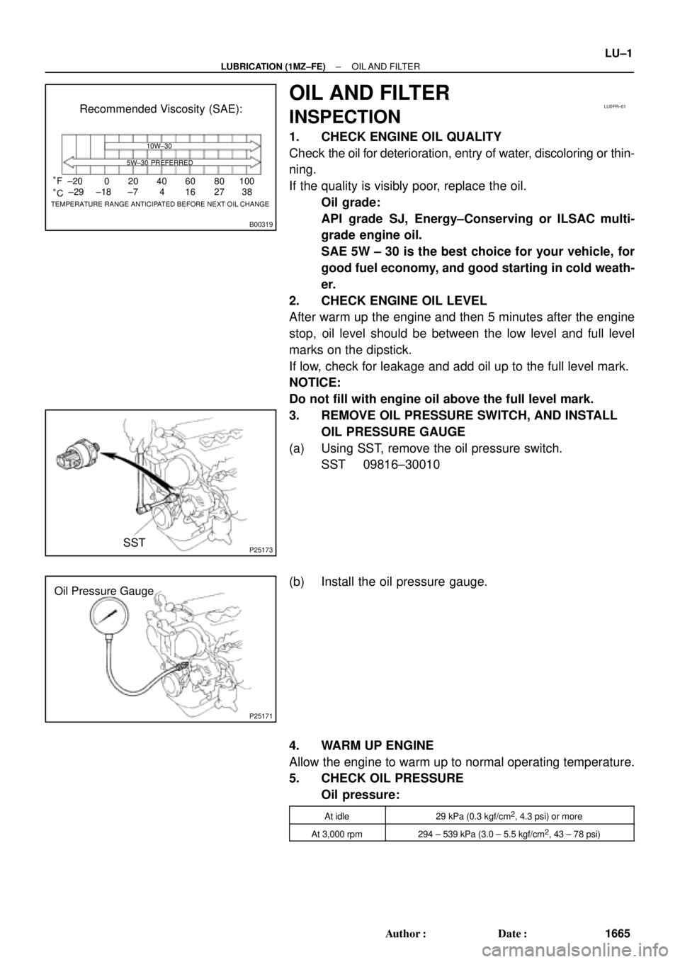
3. REMOVE OIL PRESSURE SWITCH, AND INSTALL
OIL PRESSURE GAUGE
(a) Using SST, remove the oil pressure switch.
SST 09816±30010
(b) Install the oil pressure gauge.
4. WARM UP ENGINE
Allow the engine to warm up to normal operating temperature.
5. CHECK OIL PRESSURE
Oil pressure:
At idle29 kPa (0.3 kgf/cm2, 4.3 psi) or more
At 3,000 rpm294 ± 539 kPa (3.0 ± 5.5 kgf/cm2, 43 ± 78 psi)
Page 3755 of 4770

MA00L±01
P00495
Outside
Inside
± MAINTENANCEENGINE
MA±5
48 Author�: Date�:
ENGINE
INSPECTION
1. REPLACE TIMING BELT
5S±FE: (See page EM±17)
1MZ±FE: (See page EM±15)
2. INSPECT DRIVE BELTS
5S±FE: (See page CH±1)
1MZ±FE: (See page CH±1)
3. REPLACE SPARK PLUGS
5S±FE: (See page IG±1)
1MZ±FE: (See page IG±1)
4. INSPECT AIR FILTER
(a) Visually check that the air filter is not excessively dirty or
oily.
(b) Clean the air filter with compressed air.
First blow from the inside thoroughly, then blow off the outside
of the air filter.
5. REPLACE AIR FILTER
Replace the air filter with a new one.
6. REPLACE ENGINE OIL AND OIL FILTER
5S±FE: (See page LU±2)
1MZ±FE: (See page LU±3)
7. REPLACE ENGINE COOLANT
5S±FE: (See page CO±2)
1MZ±FE: (See page CO±2)
8. 1MZ±FE:
INSPECT CHARCOAL CANISTER
(See page EC±6)
9. REPLACE GASKET IN FUEL TANK CAP
5S±FE: (See page EC±6)
1MZ±FE: (See page EC±6)
10. INSPECT FUEL LINES AND CONNECTIONS
5S±FE: (See page EC±6)
1MZ±FE: (See page EC±6)
11. INSPECT EXHAUST PIPES AND MOUNTINGS
5S±FE: (See page EC±15)
1MZ±FE: (See page EC±17)
12. ADJUST VALVE CLEARANCE
5S±FE: (See page EM±4)
1MZ±FE: (See page EM±4)
Page 3886 of 4770
PP0K6±04
± PREPARATIONLUBRICATION (5S±FE)
PP±35
87 Author�: Date�:
LUBRICANT
ItemCapacityClassification
Engine oil
Dry fill w/ Oil cooler
w/o Oil cooler
Drain and refill
w/ Oil filter change
w/o Oil filter change
4.3 liters (4.5 US qts, 3.8 lmp.qts)
4.2 liters (4.4 US qts, 3.7 lmp.qts)
3.6 liters (3.8 US qts, 3.2 lmp.qts)
3.4 liters (3.6 US qts, 3.0 lmp.qts)
API grade SJ, Energy±Conserving or ILSAC mul-
tigrade engine oil. SAE 5W±30 is the best choice
for your vehicle, for good fuel economy, and good
starting in cold weather