Page 4044 of 4770
S06038
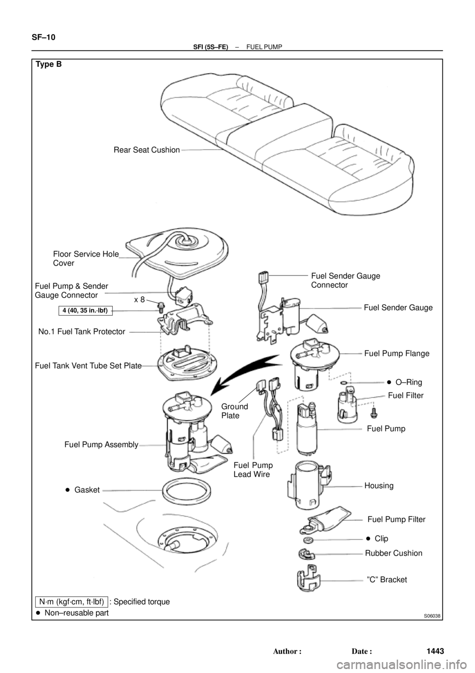
Type B
Rear Seat Cushion
� Gasket
4 (40, 35 in.´lbf)
Floor Service Hole
Cover
Fuel Pump & Sender
Gauge Connector
No.1 Fuel Tank Protector
Fuel Tank Vent Tube Set Plate
Fuel Filter Fuel Pump Flange
Fuel Pump
Fuel Pump Filter
� Clip
Rubber Cushion Fuel Pump Assembly
N´m (kgf´cm, ft´lbf)
� Non±reusable part� O±Ring
Housing
ºCº Bracket Fuel Sender Gauge
Fuel Pump
Lead Wire
: Specified torqueFuel Sender Gauge
Connector
Ground
Plate
x 8
SF±10
± SFI (5S±FE)FUEL PUMP
1443 Author�: Date�:
Page 4045 of 4770
FUEL PUMP
SF±11
1444 Author�: Date�:
REMOVAL
CAUTION:
Do not smoke or work near an open flame when working on
the fuel pump.
1. REMOVE REAR SEAT CUSHI")
SF0D9±03
S04583
S04592
Vinyl Bag
± SFI (5S±FE)FUEL PUMP
SF±11
1444 Author�: Date�:
REMOVAL
CAUTION:
Do not smoke or work near an open flame when working on
the fuel pump.
1. REMOVE REAR SEAT CUSHION
2. REMOVE FLOOR SERVICE HOLE COVER
(a) Take out the floor carpet.
(b) Remove the service hole cover.
HINT:
At the time of installation, please refer to the following items.
Check for fuel leakage.
3. DISCONNECT FUEL PUMP & SENDER GAUGE CON-
NECTOR
4. REMOVE NO.1 FUEL TANK PROTECTOR
Remove the 2 bolts and No.1 fuel tank protector.
Torque: 4 N´m (40 kgf´cm, 35 in.´lbf)
5. DISCONNECT FUEL TUBE (FUEL TUBE CONNEC-
TOR)
CAUTION:
�Perform disconnecting and connecting operations of
the fuel tube connector (quick type) after observing
the precautions.
�As there is retained pressure in the fuel pipe line, pre-
vent it from splashing inside the vehicle compart-
ment.
6. REMOVE FUEL PUMP ASSEMBLY FROM FUEL TANK
(a) Remove the 6 bolts and fuel tank vent tube set plate.
Torque: 4 N´m (40 kgf´cm, 35 in.´lbf)
(b) Pull out the fuel pump assembly.
(c) Remove the gasket from the pump assembly.
NOTICE:
�Do not damage the fuel pump filter.
�Be careful that the arm of the sender gauge should
not bent.
HINT:
At the time of installation, please refer to the following items.
Install a new gasket to the pump assembly.
Page 4046 of 4770
(3)
(2) Type B SF±12
± SFI (5S±FE)FUEL PUMP
1445 Author�: Date�:
DISASSEMBLY
1. DISCONNECT FUEL PUMP CONNECTOR")
SF0DA±02
S06028
Type B
S04603Pull Type A
S06033
PushA Type B
S06050
Type B
S06030
(1)(3)
(2) Type B SF±12
± SFI (5S±FE)FUEL PUMP
1445 Author�: Date�:
DISASSEMBLY
1. DISCONNECT FUEL PUMP CONNECTOR
2. Type B:
DISCONNECT GROUND PLATE
3. Type B:
DISCONNECT FUEL SENDER GAUGE CONNECTOR
4. Type A:
REMOVE FUEL PUMP FROM FUEL PUMP BRACKET
(a) Pull off the lower side of the fuel pump from the pump
bracket.
(b) Disconnect the fuel hose from the fuel pump, and remove
the fuel pump.
(c) Remove the rubber cushion from the fuel pump.
5. Type B:
REMOVE FUEL SENDER GAUGE.
Push down the portion of A with a finger, and push up the send-
er gauge.
NOTICE:
Be careful that the arm of the sender gauge should not
bent.
6. Type B:
REMOVE FUEL FILTER
(a) Remove the screw, and pull out the fuel filter.
(b) Remove the O±ring from the fuel filter.
HINT:
At the time of installation, please refer to the following items. Ap-
ply a light coat of gasoline to a new O±ring, and install it to the
fuel filter.
Torque: 2.0 N´m (20 kgf´cm, 17 in.´lbf)
7. Type B:
REMOVE FUEL PUMP FLANGE
Using a screwdriver, remove the snap fit portion in the order of
1, 2 and 3 as shown in the illustration.
HINT:
At the time of installation, please refer to the following items. Ap-
ply a light coat of gasoline to a new O±ring of the fuel pump.
Page 4047 of 4770
S06027
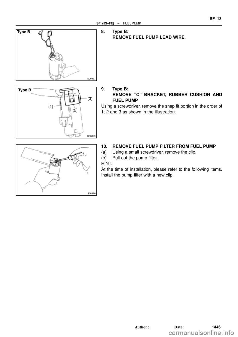
Type B
S06029
(1)(3)
(2)
Type B
FI6376
± SFI (5S±FE)FUEL PUMP
SF±13
1446 Author�: Date�:
8. Type B:
REMOVE FUEL PUMP LEAD WIRE.
9. Type B:
REMOVE ºCº BRACKET, RUBBER CUSHION AND
FUEL PUMP
Using a screwdriver, remove the snap fit portion in the order of
1, 2 and 3 as shown in the illustration.
10. REMOVE FUEL PUMP FILTER FROM FUEL PUMP
(a) Using a small screwdriver, remove the clip.
(b) Pull out the pump filter.
HINT:
At the time of installation, please refer to the following items.
Install the pump filter with a new clip.
Page 4050 of 4770
SF0DD±02
Z19026
Type A
Rear Seat Cushion
Floor Service Hole Cover
Fuel Pump & Sender
Gauge Connector
No.1 Fuel Tank Protector
Fuel Tank Vent Tube Set Plate
Fuel Pressure
Regulator
Fuel Filter Fuel Pump Assembly
� Gasket
N´m (kgf´cm, ft´lbf)� O±Ring � O±Ring
� Non±reusable part
4 (40, 35 in.´lbf)
: Specified torquex 8
SF±16
± SFI (5S±FE)FUEL PRESSURE REGULATOR
1449 Author�: Date�:
FUEL PRESSURE REGULATOR
COMPONENTS
Page 4051 of 4770
S06037
Type B
Rear Seat Cushion
Floor Service Hole Cover
Fuel Pump and Sender
Gauge Connector
No.1 Fuel Tank Protector
Fuel Tank Vent Tube Set Plate
Fuel Pressure
Regulator
Fuel Filter Fuel Pump Assembly
� Gasket
N´m (kgf´cm, ft´lbf)� O±Ring � O±Ring
� Non±reusable part
4 (40, 35 in.´lbf)
: Specified torquex 8
± SFI (5S±FE)FUEL PRESSURE REGULATOR
SF±17
1450 Author�: Date�:
Page 4052 of 4770
SF0DE±03
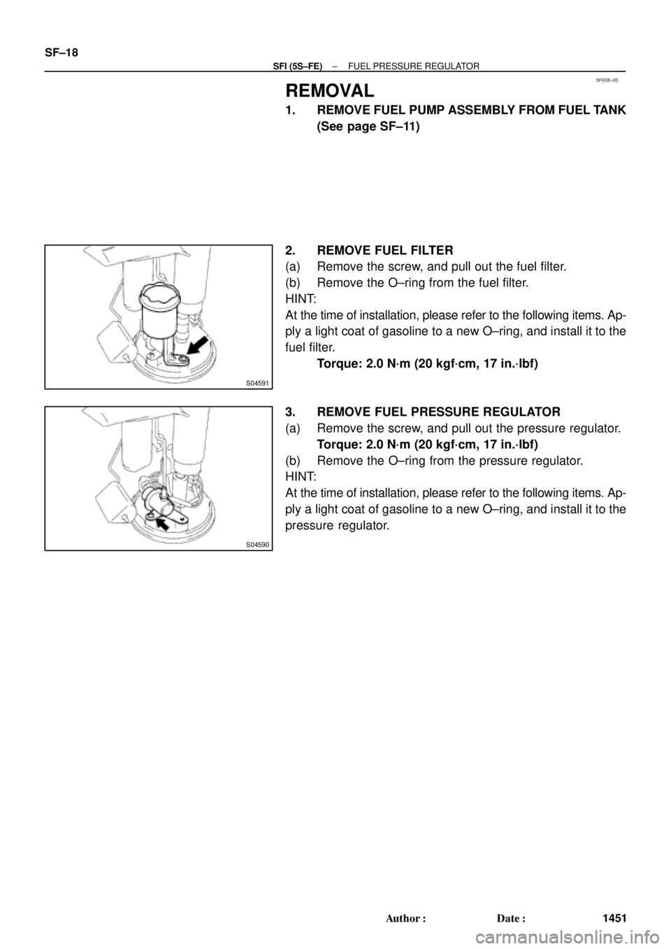
S04591
S04590
SF±18
± SFI (5S±FE)FUEL PRESSURE REGULATOR
1451 Author�: Date�:
REMOVAL
1. REMOVE FUEL PUMP ASSEMBLY FROM FUEL TANK
(See page SF±11)
2. REMOVE FUEL FILTER
(a) Remove the screw, and pull out the fuel filter.
(b) Remove the O±ring from the fuel filter.
HINT:
At the time of installation, please refer to the following items. Ap-
ply a light coat of gasoline to a new O±ring, and install it to the
fuel filter.
Torque: 2.0 N´m (20 kgf´cm, 17 in.´lbf)
3. REMOVE FUEL PRESSURE REGULATOR
(a) Remove the screw, and pull out the pressure regulator.
Torque: 2.0 N´m (20 kgf´cm, 17 in.´lbf)
(b) Remove the O±ring from the pressure regulator.
HINT:
At the time of installation, please refer to the following items. Ap-
ply a light coat of gasoline to a new O±ring, and install it to the
pressure regulator.
Page 4057 of 4770
Union Bolt
SST (Union)
Injector Fuel Filter
(On Vehicle)SST
(Clamp)
SST
(Union)
S05522
S05524
Union Bolt
Gasket SST (Union)
SST (Hose)
P01078
SST
(Clamp) O±Ring
Vinyl
Tube")
SF0DJ±03
S05525
SST (Hose)Union Bolt
SST (Union)
Injector Fuel Filter
(On Vehicle)SST
(Clamp)
SST
(Union)
S05522
S05524
Union Bolt
Gasket SST (Union)
SST (Hose)
P01078
SST
(Clamp) O±Ring
Vinyl
Tube SST (Union)SST (Hose)
S05331
± SFI (5S±FE)INJECTOR
SF±23
1456 Author�: Date�:
INSPECTION
1. INSPECT INJECTOR INJECTION
CAUTION:
Keep injector clean of sparks during the test.
(a) Remove the union bolt and 2 gaskets, and disconnect the
fuel inlet hose from the fuel filter outlet.
(b) Connect SST (union and hose) to the fuel filter outlet with
the 2 gaskets and union bolts.
SST 09268±41047 (90405±09015)
Torque: 29 N´m (300 kgf´cm, 21 ft´lbf)
(c) Install the grommet and O±ring to the injector.
(d) Connect SST (union and hose) to the injector, and hold
the injector and union with SST (clamp).
SST 09268±41047 (09268±41100, 09268±41110)
(e) Put the injector into the graduated cylinder.
CAUTION:
Install a suitable vinyl hose onto the injector to prevent
gasoline from splashing out.
(f) Connect a TOYOTA hand±held tester to the DLC3.
(g) Connect the battery negative (±) cable to the battery.
(h) Turn the ignition switch ON and push the TOYOTA hand±
held tester main switch ON.
NOTICE:
Do not start the engine.
(i) Select the ACTIVE TEST mode on the TOYOTA hand±
held tester.
(j) Please refer to the TOYOTA hand±held tester operator's
manual for further details.