Page 3891 of 4770
PP0C7±04
PP±40
± PREPARATIONLUBRICATION (1MZ±FE)
92 Author�: Date�:
LUBRICANT
ItemCapacityClassification
Engine oil
Dry fill
Drain and refill
w/ Oil filter change
w/o Oil filter change
5.2 liters (5.5 US qts, 4.6 lmp. qts)
4.7 liters (5.0 US qts, 4.1 lmp. qts)
4.5 liters (4.8 US qts, 4.0 lmp. qts)
API grade SJ, Energy±Conserving or ILSAC
multigrade engine oil.
SAE 5W±30 is the best choice for your vehicle,
for good fuel economy and good starting in cold
weather.
Page 3972 of 4770

173 Author�: Date�:
LH stiffener plate x Transaxle M/T
A/T37
42380
43027
31
No.2 RH engine mounting bracket x Cylinder block5253038
No.2 RH e")
SS±10
± SERVICE SPECIFICATIONSENGINE MECHANICAL (5S±FE)
173 Author�: Date�:
LH stiffener plate x Transaxle M/T
A/T37
42380
43027
31
No.2 RH engine mounting bracket x Cylinder block5253038
No.2 RH engine mounting bracket x Generator bracket5253038
Rear engine mounting insulator x Cylinder block6465047
Front engine mounting insulator x Cylinder block6465047
Engine moving control rod x No.2 RH engine mounting bracket6465047
Engine moving control rod x Body6465047
Front engine mounting insulator x Front frame TMC made
TMMK made for silver color
for green color80
44
66820
450
67059
32
49
Rear engine mounting insulator x Front frame6667049
LH engine mounting insulator x Frount frame8082059
LH engine mounting insulator x Transaxle6465047
PS pump x PS pump bracket4344032
A/C compressor x Cylinder block25.526019
Fuel inlet hose x Fuel filter2930021
Main bearing cap x Cylinder block5960043
Connecting rod cap x Connecting rod 1st
2nd25
Turn 90°250
Turn 90°18
Turn 90°
Engine balancer x Cylinder block4950036
Rear oil seal retainer x Cylinder block131309
Water pump x Cylinder block8.89078 in.´lbf
Generator drive belt adjusting bar x Cylinder block2222416
PS pump bracket x Cylinder block4344032
Front exhaust pipe x Exhaust manifold6263046
Front exhaust pipe x Center pipe5657041
Center exhaust pipe x Tailpipe5657041
Support bracket for front exhaust pipe
x Exhaust pipe bracket on No.2 rear end plate3333024
Support stay for front exhaust pipe x Support bracket3333024
Support bracket for front exhaust pipe x Front frame3333024
Support bracket for center exhaust pipe x Body1919514
Support bracket for tailpipe x Body3333024
Page 3976 of 4770

177 Author�: Date�:
TORQUE SPECIFICATION
Part tightenedN´mkgf´cmft´lbf
Timing belt plate x Oil pump88069 in.´lbf
No.1 idler pu")
SS077±03
SS±14
± SERVICE SPECIFICATIONSENGINE MECHANICAL (1MZ±FE)
177 Author�: Date�:
TORQUE SPECIFICATION
Part tightenedN´mkgf´cmft´lbf
Timing belt plate x Oil pump88069 in.´lbf
No.1 idler pulley x Oil pump3435025
No.2 idler pulley x No.2 idler pulley bracket4344032
Camshaft timing pulley x Camshaft
for SST125
881,300
90094
65
Timing belt tensioner x Oil pump2728020
RH engine mounting bracket x Cylinder block2829021
No.2 timing belt cover x No.3 timing belt cover8.58574 in.´lbf
No.1 timing belt cover x Oil pump8.58574 in.´lbf
Crankshaft pulley x Crankshaft2152,200159
No.2 generator bracket x Engine RH mounting bracket2829021
Cylinder head x Cylinder block 12 pointed head bolt 1st
2nd
Recessed head bolt54
Turn 90°
18.5550
Turn 90°
18540
Turn 90°
13
Camshaft bearing cap x Cylinder head1616012
Cylinder head cover x Cylinder head88069 in.´lbf
Exhaust manifold x Cylinder head4950036
Exhaust manifold stay x Exhaust manifold
Except California A/T and all M/T
California A/T and all M/T
20
34200
35015
25
Exhaust manifold stay x Transmission housing
Except California A/T
California A/T
20
34200
35015
25
No.1 EGR pipe x RH exhaust manifold121209
No.1 EGR pipe x EGR cooler121209
PS pump bracket x RH cylinder head4344032
Oil dipstick guide x LH cylinder head88069 in.´lbf
Water inlet pipe x LH cylinder head19.520014
Cylinder head rear plate x LH cylinder head88069 in.´lbf
No.3 timing belt cover x Cylinder head8.58574 in.´lbf
Water outlet x Intake manifold1515011
Fuel inlet hose x Fuel filter2930021
Intake manifold x Cylinder head1515011
Air intake chamber x Intake manifold4344032
No.2 EGR pipe x Air intake chamber121209
No.2 EGR pipe x EGR cooler121209
No.1 engine hanger x Air intake chamber3940029
No.1 engine hanger x RH cylinder head3940029
Air intake chamber stay x Air intake chamber19.520014
Air intake chamber stay x RH cylinder head19.520014
Rear engine mounting insulator x Cylinder block6465047
Front engine mounting insulator x Cylinder block6465047
Engine moving control rod x RH engine mounting bracket6465047
Engine moving control rod x RH fender apron6465047
No.2 RH engine mounting stay x No.2 RH engine mounting bracket6465047
Page 3982 of 4770
SS0AH±03
SS±20
± SERVICE SPECIFICATIONSSFI (5S±FE)
183 Author�: Date�:
TORQUE SPECIFICATION
Part tightenedN´mkgf´cmft´lbf
Fuel line
Union bolt type
Flare nut type for use with SST
29
28
300
285
21
21
Fuel pump assembly x Fuel tank44035 in.´lbf
Fuel filter x Fuel pump bracket22017 in.´lbf
Fuel pressure regulator x Fuel pump bracket22017 in.´lbf
Delivery pipe x Cylinder head131309
Fuel tank band x Body3940029
Throttle body x Intake manifold1919514
Knock sensor 1 x Cylinder block4445032
A/F sensor x Exhaust manifold4445032
Oxygen sensor (bank 1 sensor 1) x Exhaust manifold4445032
Oxygen sensor (bank 1 sensor 2) x Front exhaust pipe4445032
Page 3984 of 4770
SS10A±01
SS±22
± SERVICE SPECIFICATIONSSFI (1MZ±FE)
185 Author�: Date�:
TORQUE SPECIFICATION
Part tightenedN´mkgf´cmft´lbf
Fuel line (Union bolt type)2930021
Fuel line (Flare nut type) using SST2828521
Fuel pump assembly x Fuel tank44035 in.´lbf
Fuel filter x Fuel pump bracket22017 in.´lbf
Fuel pressure regulator x Fuel pump bracket22017 in.´lbf
Delivery pipe x Intake manifold101007
No.1 fuel pipe x Intake manifold19.520014
Fuel tank band x Body3940029
Throttle body x Air intake chamber19.520014
Intake air control valve x Air intake chamber14.514510
ECT sensor x Water outlet2020014
Knock sensor x Cylinder block3940029
A/F sensor x Exhaust manifold4445032
Heated oxygen sensor (Bank 1, 2 sensor 1) x Exhaust manifold4445032
Heated oxygen sensor (Bank 1 sensor 2) x Exhaust pipe4445032
Page 4040 of 4770
FUEL PUMP
1439 Author�: Date�:
FUEL PUMP
ON±VEHICLE INSPECTION
1. CHECK FUEL PUMP OPERATION
(a) Connect a TOYOTA hand±held tester")
S05331
SF0D7±03
S05327
Fuel Inlet Hose
S05522
SF±6
± SFI (5S±FE)FUEL PUMP
1439 Author�: Date�:
FUEL PUMP
ON±VEHICLE INSPECTION
1. CHECK FUEL PUMP OPERATION
(a) Connect a TOYOTA hand±held tester to the DLC3.
(b) Turn the ignition switch ON and push the TOYOTA hand±
held tester main switch ON.
NOTICE:
Do not start the engine.
(c) Select the ACTIVE TEST mode on the TOYOTA hand±
held tester.
(d) Please refer to the TOYOTA hand±held tester operator's
manual for further details.
(e) If you have no TOYOTA hand±held tester, connect the
positive (+) and negative (±) leads from the battery to the
fuel pump connector. (See step 7)
(f) Check that there is pressure in the fuel inlet hose from the
fuel filter.
HINT:
If there is fuel pressure, you will hear the sound of fuel flowing.
If there is no pressure, check the fusible link, fuses, EFI main
relay, fuel pump, ECM and wiring connections.
(g) Turn the ignition switch OFF.
(h) Disconnect the TOYOTA hand±held tester from the
DLC3.
2. CHECK FUEL PRESSURE
(a) Check the battery positive voltage is above 12 V.
(b) Disconnect the negative (±) terminal cable from the bat-
tery.
(c) Remove the union bolt and 2 gaskets, and disconnect the
fuel inlet hose from the fuel filter outlet.
CAUTION:
�Put a shop towel under the fuel filter.
�Slowly loosen the union bolt.
Page 4041 of 4770
GasketSST (Union Bolt)
SST
(Gauge)
Gasket
S04508
Ohmmeter
4
5
± SFI (5S±FE)FUEL PUMP
SF±7
1440 Author�: Date�:
(d) Install the fuel inlet hose and SST (pres")
S05328
Fuel Inlet
Hose
Gasket
SST (Union)GasketSST (Union Bolt)
SST
(Gauge)
Gasket
S04508
Ohmmeter
4
5
± SFI (5S±FE)FUEL PUMP
SF±7
1440 Author�: Date�:
(d) Install the fuel inlet hose and SST (pressure gauge) to the
fuel filter outlet with the 3 gaskets and SST (union bolt).
SST 09268±45014 (09268±41190, 90405±06167)
Torque: 29 N´m (300 kgf´cm, 21 ft´lbf)
(e) Wipe off any splattered gasoline.
(f) Reconnect the negative (±) terminal cable to the battery.
(g) Connect a TOYOTA hand±held tester to the DLC3.
(See step 1 in check fuel pump operation (a) to (e))
(h) Measure the fuel pressure.
Fuel pressure:
301 ± 347 kPa (3.1 ± 3.5 kgf/cm
2, 44 ± 50 psi)
If pressure is high, replace the fuel pressure regulator.
If pressure is low, check the fuel hoses, fuel hose connections,
fuel pump, fuel filter and fuel pressure regulator.
(i) Disconnect the TOYOTA hand±held tester from the
DLC3.
(j) Start the engine.
(k) Measure the fuel pressure at idle.
Fuel pressure:
301 ± 347 kPa (3.1 ± 3.5 kgf/cm
2, 44 ± 50 psi)
(l) Stop the engine.
(m) Check that the fuel pressure remains as specified for 5
minutes after the engine has stopped.
Fuel pressure:
147 kPa (1.5 kgf/cm
2, 21 psi) or more
If pressure is not as specified, check the fuel pump, pressure
regulator and/or injectors.
(n) After checking fuel pressure, disconnect the negative (±)
terminal cable from the battery and carefully remove the
SST to prevent gasoline from splashing.
SST 09268±45014
(o) Reconnect the fuel inlet hose with 2 new gaskets and the
union bolt.
Torque: 29 N´m (300 kgf´cm, 21 ft´lbf)
(p) Reconnect the negative (±) terminal cable to the battery.
(q) Check for fuel leaks. (See page SF±1)
3. REMOVE REAR SEAT CUSHION
4. REMOVE FLOOR SERVICE HOLE COVER
5. DISCONNECT FUEL PUMP & SENDER GAUGE CON-
NECTOR
6. INSPECT FUEL PUMP RESISTANCE
Using an ohmmeter, measure the resistance between terminals
4 and 5.
Resistance: 0.2 ± 3.0 W at 20°C (68°F)
If the resistance is not as specified, replace the fuel pump.
Page 4043 of 4770
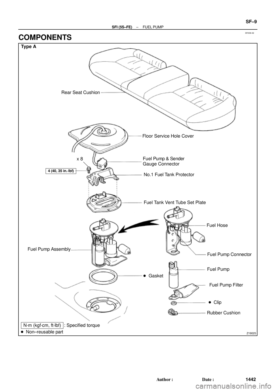
SF0D8±02
Z19025
Type A
Rear Seat Cushion
� Gasket
4 (40, 35 in.´lbf)
Floor Service Hole Cover
Fuel Pump & Sender
Gauge Connector
No.1 Fuel Tank Protector
Fuel Tank Vent Tube Set Plate
Fuel Hose
Fuel Pump Connector
Fuel Pump
Fuel Pump Filter
� Clip
Rubber Cushion Fuel Pump Assembly
N´m (kgf´cm, ft´lbf)
� Non±reusable part: Specified torquex 8
± SFI (5S±FE)FUEL PUMP
SF±9
1442 Author�: Date�:
COMPONENTS