Page 4114 of 4770
S06027
Type B
S06029
(1)(3)
(2)
Type B
FI6376
SF±14
± SFI (1MZ±FE)FUEL PUMP
1513 Author�: Date�:
8. Type B:
REMOVE FUEL PUMP LEAD WIRE
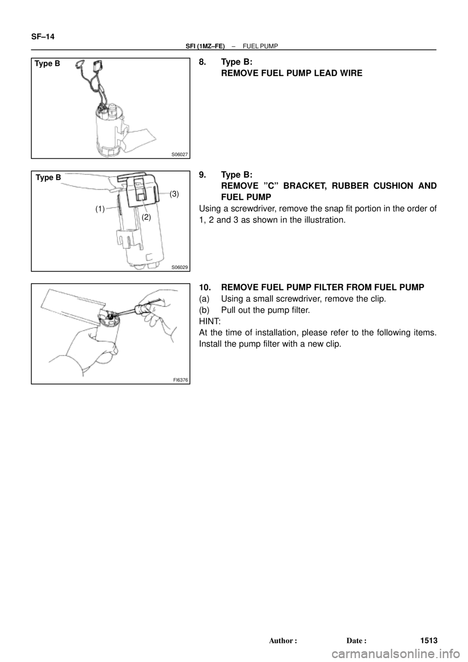
9. Type B:
REMOVE ºCº BRACKET, RUBBER CUSHION AND
FUEL PUMP
Using a screwdriver, remove the snap fit portion in the order of
1, 2 and 3 as shown in the illustration.
10. REMOVE FUEL PUMP FILTER FROM FUEL PUMP
(a) Using a small screwdriver, remove the clip.
(b) Pull out the pump filter.
HINT:
At the time of installation, please refer to the following items.
Install the pump filter with a new clip.
Page 4117 of 4770
SF07F±03
B06392
Type A
Rear Seat Cushion
Floor Service Hole Cover
Fuel Pump and Sender
Gauge Connector
No.1 Fuel Tank Protector
Fuel Tank Vent Tube Set Plate
Fuel Pressure
Regulator
Fuel Filter Fuel Pump Assembly
� Gasket
N´m (kgf´cm, ft´lbf)� O±Ring � O±Ring
� Non±reusable part: Specified torque
4 (40,35 in.´lbf)
x 8
± SFI (1MZ±FE)FUEL PRESSURE REGULATOR
SF±17
1516 Author�: Date�:
FUEL PRESSURE REGULATOR
COMPONENTS
Page 4118 of 4770
B06393
Type B
Rear Seat Cushion
Floor Service Hole Cover
Fuel Pump and Sender
Gauge Connector
No.1 Fuel Tank Protector
Fuel Tank Vent Tube Set Plate
Fuel Pressure
Regulator
Fuel Filter Fuel Pump Assembly
� Gasket
N´m (kgf´cm, ft´lbf)� O±Ring � O±Ring
� Non±reusable part: Specified torque
4 (40, 35 in.´lbf)x 8
SF±18
± SFI (1MZ±FE)FUEL PRESSURE REGULATOR
1517 Author�: Date�:
Page 4119 of 4770
SF07G±03
S04591
S04590
± SFI (1MZ±FE)FUEL PRESSURE REGULATOR
SF±19
1518 Author�: Date�:
REMOVAL
1. REMOVE FUEL PUMP ASSEMBLY FROM FUEL TANK
(See page SF±12)
2. REMOVE FUEL FILTER
(a) Remove the screw, and pull out the fuel filter.
Torque: 2.0 N´m (20 kgf´cm, 17 in.´lbf)
(b) Remove the O±ring from the fuel filter.
HINT:
At the time of installation, please refer to the following items.
Apply a light coat of gasoline to a new O±ring, and install it to
the fuel filter.
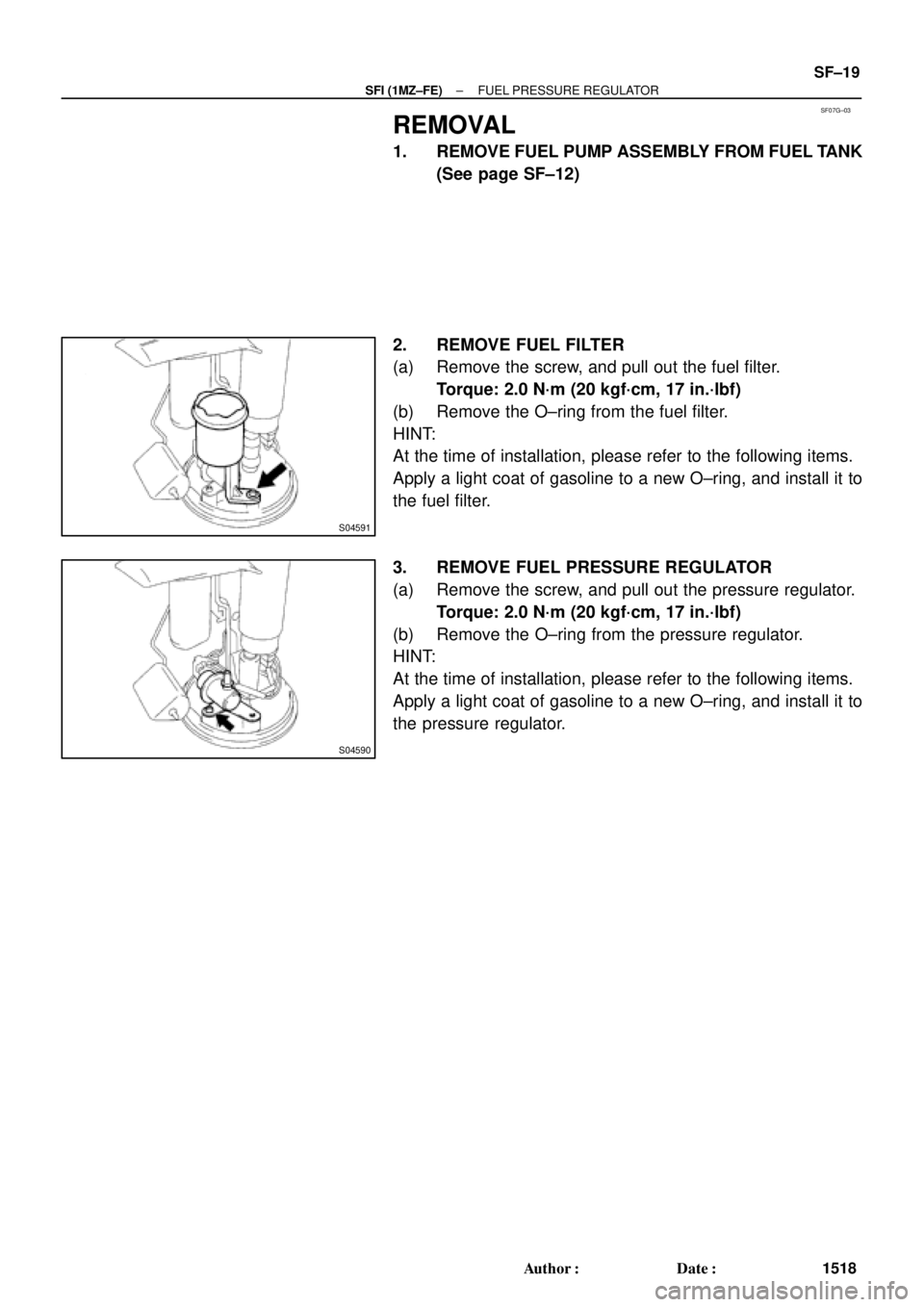
3. REMOVE FUEL PRESSURE REGULATOR
(a) Remove the screw, and pull out the pressure regulator.
Torque: 2.0 N´m (20 kgf´cm, 17 in.´lbf)
(b) Remove the O±ring from the pressure regulator.
HINT:
At the time of installation, please refer to the following items.
Apply a light coat of gasoline to a new O±ring, and install it to
the pressure regulator.
Page 4123 of 4770
SF07K±04
S04505
S04498
S06086
Fuel Hose
Clamp
S05352
± SFI (1MZ±FE)INJECTOR
SF±23
1522 Author�: Date�:
REMOVAL
1. REMOVE AIR CLEANER HOSE
2. REMOVE AIR INTAKE CHAMBER ASSEMBLY
(See page EM±32)
3. DISCONNECT INJECTOR CONNECTORS
4. REMOVE AIR ASSIST HOSES AND PIPE
(a) Disconnect the air assist pipe from the bracket on the
No.1 fuel pipe.
(b) Remove the air assist hoses from the intake manifold.
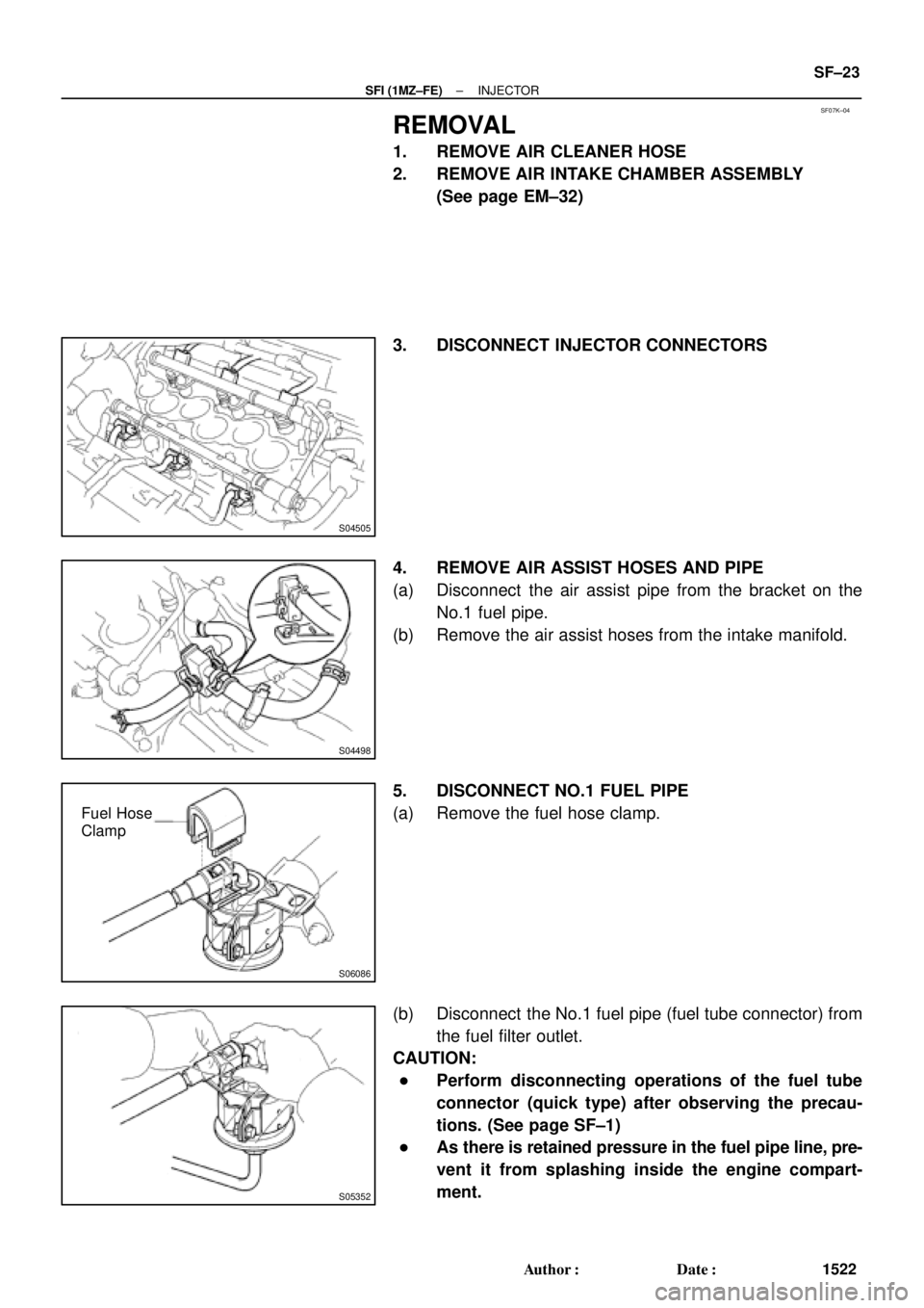
5. DISCONNECT NO.1 FUEL PIPE
(a) Remove the fuel hose clamp.
(b) Disconnect the No.1 fuel pipe (fuel tube connector) from
the fuel filter outlet.
CAUTION:
�Perform disconnecting operations of the fuel tube
connector (quick type) after observing the precau-
tions. (See page SF±1)
�As there is retained pressure in the fuel pipe line, pre-
vent it from splashing inside the engine compart-
ment.
Page 4125 of 4770
SF07L±04
B01919
Fuel Tube Connector
SST
(Hose)
SST
(Union)
SST
(Clamp)
InjectorFuel Filter
(On Vehicle) California A/T
Except California A/T
Fuel Tube Connector
SST
(Hose)
SST
(Union)
SST
(Clamp)
InjectorFuel Filter
(On Vehicle)
S05359
Fuel Tube Connector
S05357
SST
(Hose) Fuel Tube Connector
Fuel Filter
± SFI (1MZ±FE)INJECTOR
SF±25
1524 Author�: Date�:
INSPECTION
1. INSPECT INJECTOR INJECTION
CAUTION:
Keep injector clear of sparks during the test.
(a) Purchase the new No.1 fuel pipe and take out the fuel
tube connector from its pipe.
Part No. 23801±20041
(b) Connect SST (hose ) and fuel tube connector to the fuel
filter outlet.
SST 09268±41047
CAUTION:
Preform connecting operations of the fuel tube connector
(quick type) after observing the precautions.
(See page SF±1)
HINT:
Use the vehicle fuel filter.
Page 4129 of 4770
INJECTOR
SF±29
1528 Author�: Date�:
(g) Apply a light coat of spindle oil or gasoline on the place
where a intake manifold touc")
B01021
S04728
Rotate
Outward
B01020
S06525
Align
S05351
± SFI (1MZ±FE)INJECTOR
SF±29
1528 Author�: Date�:
(g) Apply a light coat of spindle oil or gasoline on the place
where a intake manifold touches an O±ring of the injector.
(h) Place the delivery pipes and fuel pipe together with the 6
injectors in position on the intake manifold.
(i) Temporarily install the 4 bolts holding the delivery pipes
to the intake manifold.
(j) Temporarily install the bolt holding the No.1 fuel pipe to
the intake manifold.
(k) Check that the injectors rotate smoothly.
HINT:
If injectors do not rotate smoothly, the probable cause is incor-
rect installation of O±rings. Replace the O±rings.
(l) Position the injector connector outward.
(m) Tighten the 4 bolts holding the delivery pipes to the intake
manifold.
Torque: 10 N´m (100 kgf´cm, 7 ft´lbf)
(n) Tighten the bolt holding the No.1 fuel pipe to the intake
manifold.
Torque: 19.5 N´m (200 kgf´cm, 14 ft´lbf)
2. CONNECT NO.1 FUEL PIPE
(a) Align the alignment marks (white paint) on the No.1 fuel
pipe.
(b) Connect the No.1 fuel pipe (fuel tube connector) to the
fuel filter.
CAUTION:
Perform connecting operations of the fuel tube connector
(quick type) after observing the precaution.
(See page SF±1)
Page 4130 of 4770
S06086
Fuel Hose
Clamp
S04498
SF±30
± SFI (1MZ±FE)INJECTOR
1529 Author�: Date�:
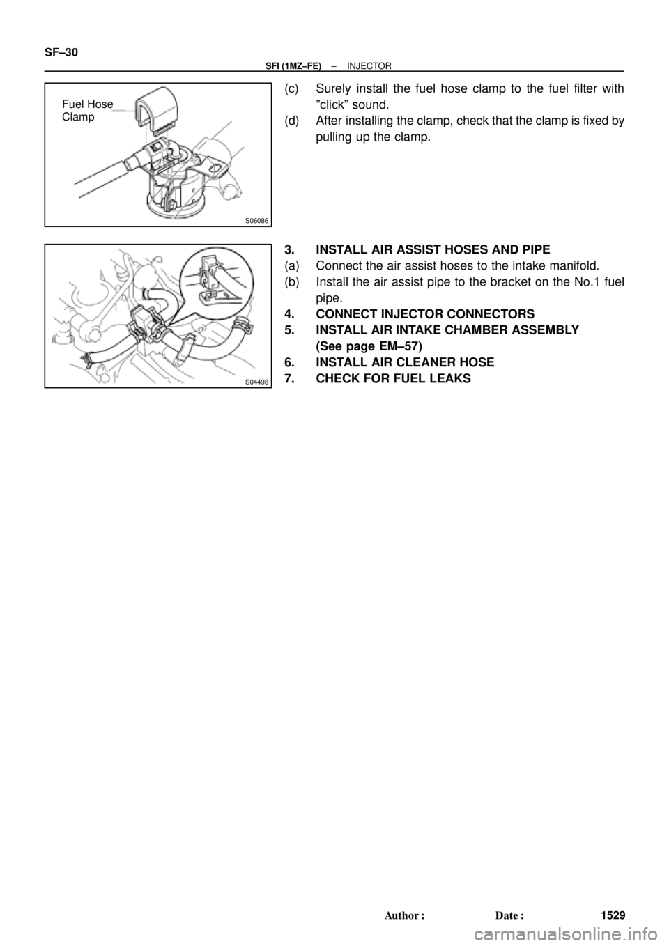
(c) Surely install the fuel hose clamp to the fuel filter with
ºclickº sound.
(d) After installing the clamp, check that the clamp is fixed by
pulling up the clamp.
3. INSTALL AIR ASSIST HOSES AND PIPE
(a) Connect the air assist hoses to the intake manifold.
(b) Install the air assist pipe to the bracket on the No.1 fuel
pipe.
4. CONNECT INJECTOR CONNECTORS
5. INSTALL AIR INTAKE CHAMBER ASSEMBLY
(See page EM±57)
6. INSTALL AIR CLEANER HOSE
7. CHECK FOR FUEL LEAKS


SST
(Union)
SST
(Clamp)
InjectorFuel Filter
(On Vehicle) California A/T
Except California A/T
Fuel Tube Connector
SST
(Hose)
SST
(Union)
SST
(Clamp)
Inj")