Page 3725 of 4770
LU03N±03
S01162
S01485
SST
± LUBRICATION (5S±FE)OIL PUMP
LU±11
1657 Author�: Date�:
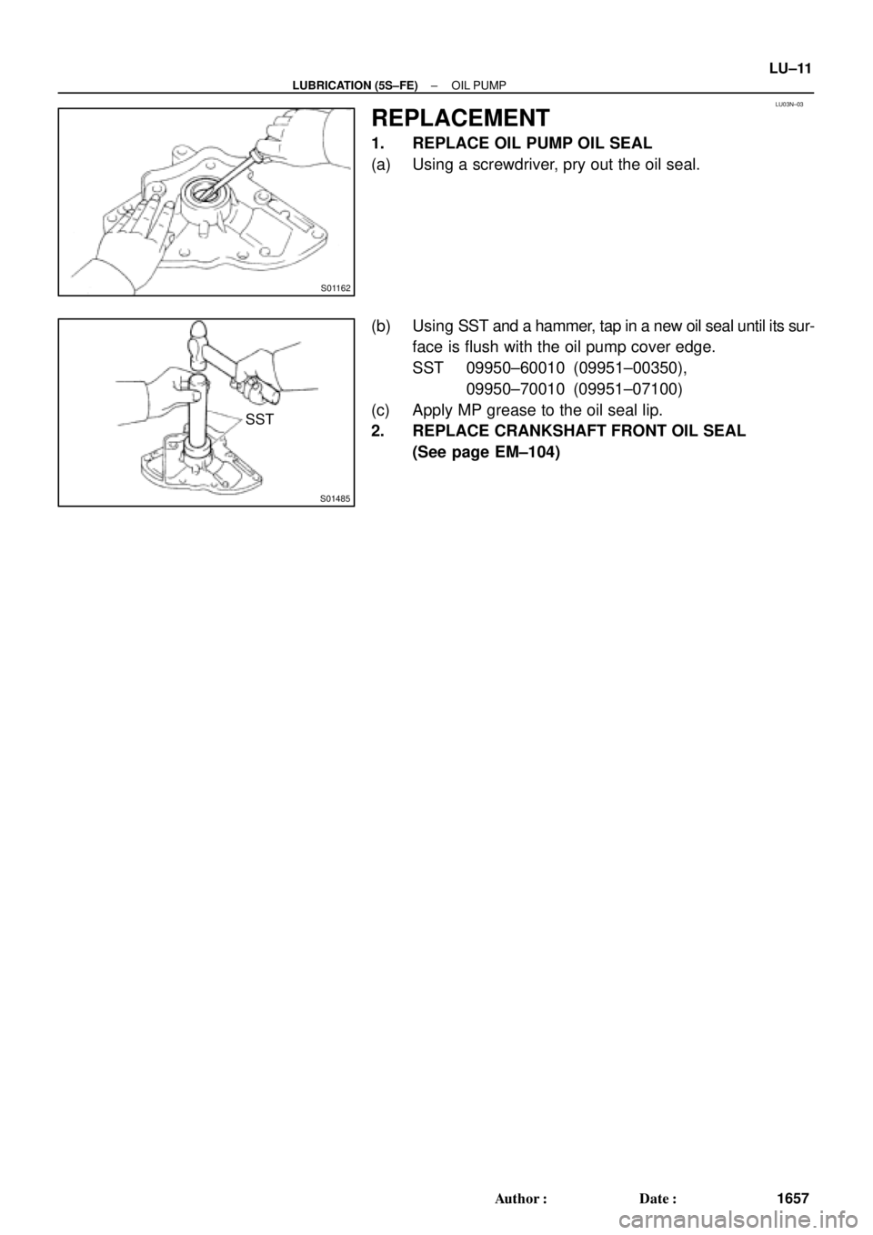
REPLACEMENT
1. REPLACE OIL PUMP OIL SEAL
(a) Using a screwdriver, pry out the oil seal.
(b) Using SST and a hammer, tap in a new oil seal until its sur-
face is flush with the oil pump cover edge.
SST 09950±60010 (09951±00350),
09950±70010 (09951±07100)
(c) Apply MP grease to the oil seal lip.
2. REPLACE CRANKSHAFT FRONT OIL SEAL
(See page EM±104)
Page 3726 of 4770
LU0FP±01
S01487
Downward Mark
S01169
S01168
LU±12
± LUBRICATION (5S±FE)OIL PUMP
1658 Author�: Date�:
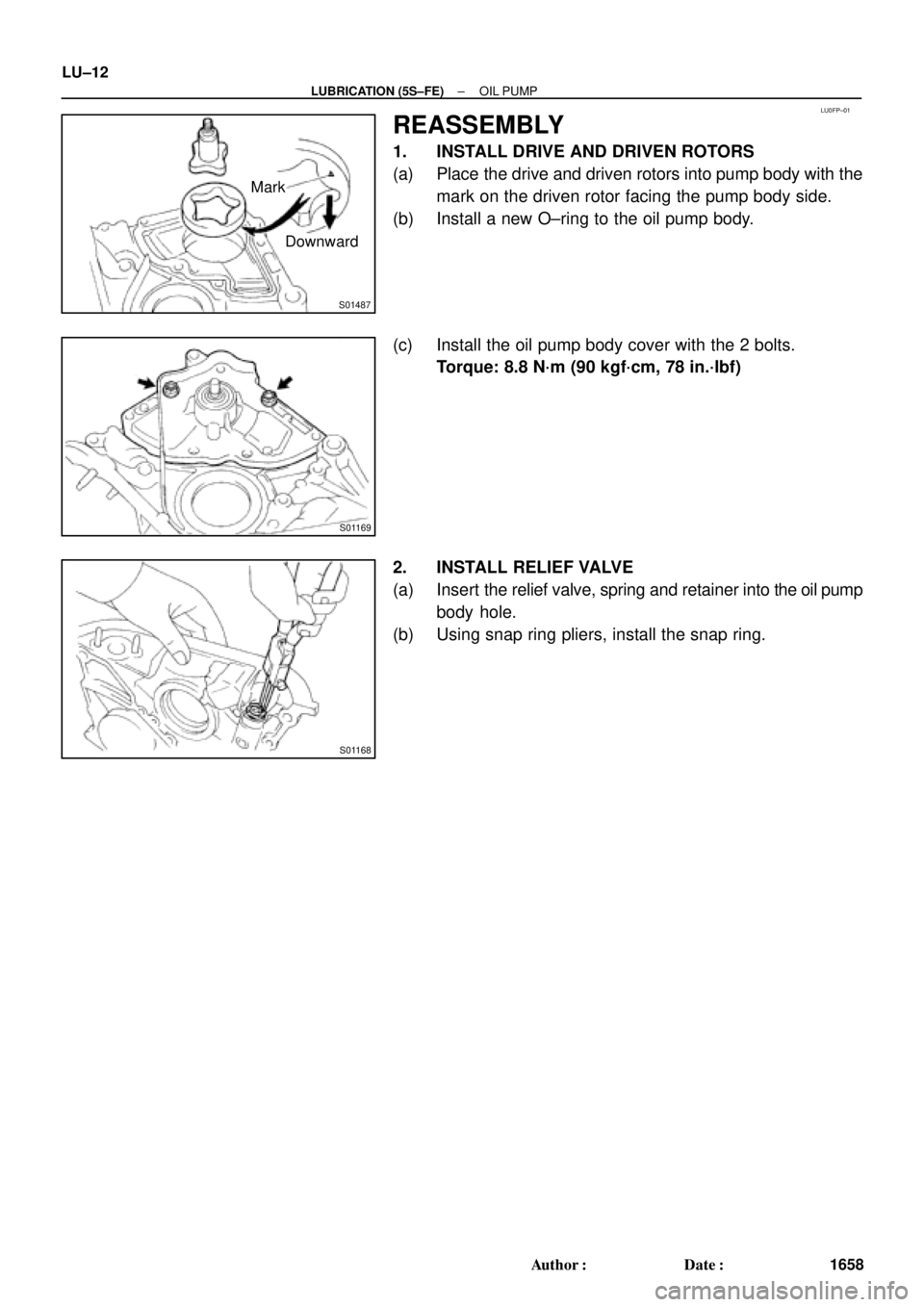
REASSEMBLY
1. INSTALL DRIVE AND DRIVEN ROTORS
(a) Place the drive and driven rotors into pump body with the
mark on the driven rotor facing the pump body side.
(b) Install a new O±ring to the oil pump body.
(c) Install the oil pump body cover with the 2 bolts.
Torque: 8.8 N´m (90 kgf´cm, 78 in.´lbf)
2. INSTALL RELIEF VALVE
(a) Insert the relief valve, spring and retainer into the oil pump
body hole.
(b) Using snap ring pliers, install the snap ring.
Page 3727 of 4770

± LUBRICATION (5S±FE)OIL PUMP
LU±13
1659 Author�: Date�:
INSTALLATION
1. INSTALL OIL PUMP
Install")
LU03P±03
Z19249
A
BB AA A AA A
A A
A
S05928
LU0420
Seal Width
3 ± 5 mm
A
A
BBC
C
5 mm (0.20 in.)
± LUBRICATION (5S±FE)OIL PUMP
LU±13
1659 Author�: Date�:
INSTALLATION
1. INSTALL OIL PUMP
Install a new gasket and the oil pump with the 12 bolts. Uniformi-
ty tighten the bolts in several passes.
Torque: 8.8 N´m (90 kgf´cm, 78 in.´lbf)
HINT:
Each bolt length is indicated in the illustration.
Bolt length:
25 mm (0.98 in.) for A
35 mm (1.38 in.) for B
2. INSTALL OIL PUMP PULLEY (See page EM±23)
3. INSTALL CRANKSHAFT TIMING PULLEY
(See page EM±23)
4. INSTALL NO.2 IDLER PULLEY (See page EM±23)
5. INSTALL TIMING BELT (See page EM±23)
6. INSTALL OIL STRAINER
Install a new gasket and the oil strainer with the bolt and 2 nuts.
Torque: 5.4 N´m (55 kgf´cm, 48 in.´lbf)
7. INSTALL OIL PAN
(a) Remove any old seal packing (FIPG) material and be
careful not to drop any oil on the contact surfaces of the
oil pan and cylinder block.
�Using a razor blade and gasket scraper, remove all
the old packing (FIPG) material from the gasket sur-
faces and sealing groove.
�Thoroughly clean all components to remove all the
loose material.
�Using a non±residue solvent, clean both sealing
surface.
NOTICE:
Do not use a solvent which will affect the painted surfaces.
(b) Apply seal packing to the oil pan shown in the illustration.
Seal packing: Part No. 08826±00080 or equivalent
�Install a nozzle that has been cut to a 3 ± 5 mm (0.12
± 0.20 in.) opening.
�Parts must be assembled within 5 minutes of ap-
plication. Otherwise the material must be removed
and reapplied.
Page 3728 of 4770
LU±14
± LUBRICATION (5S±FE)OIL PUMP
1660 Author�: Date�: �
Immediately remove nozzle from the tube and rein-
stall the cap.
(c) Install the oil pan with the 17 bolts and 2 nuts. Uniformly
tighten the bolts and nuts in several passes.
(d) Install the dipstick.
8. INSTALL NO.2 REAR END PLATE, OIL PAN INSULA-
TOR AND EXHAUST PIPE BRACKET
(See page EM±75)
9. INSTALL LH STIFFENER PLATE AND NO.2 EXHAUST
MANIFOLD STAY (See page EM±23)
10. INSTALL FRONT EXHAUST PIPE
(See page EM±75)
11. FILL WITH ENGINE OIL
12. START ENGINE AND CHECK FOR OIL LEAKS
13. RECHECK ENGINE OIL LEVEL
Page 3729 of 4770
LU03Q±03
S05996
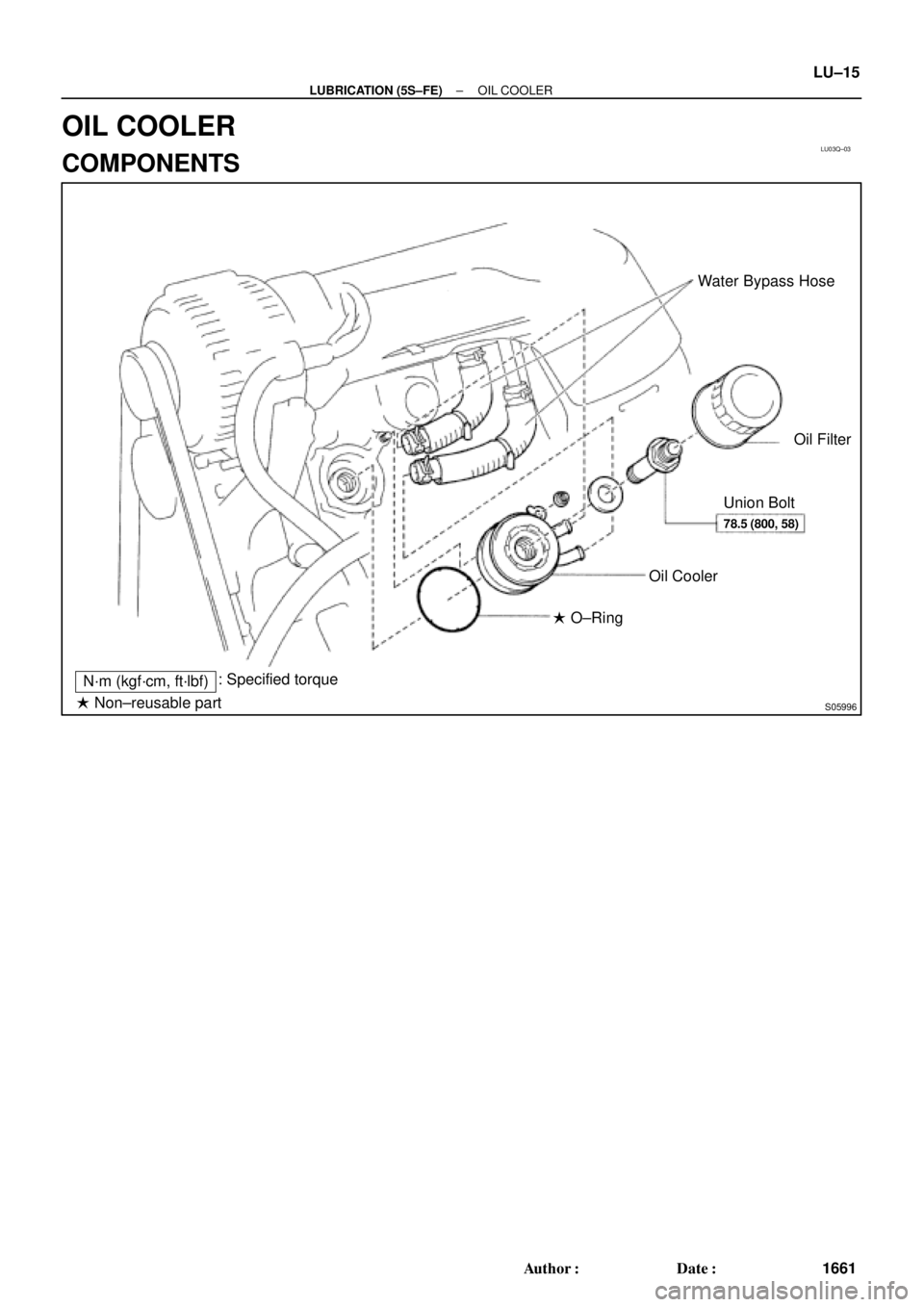
Water Bypass Hose
Oil Filter
Union Bolt
Oil Cooler
� O±Ring
N´m (kgf´cm, ft´lbf): Specified torque
� Non±reusable part
78.5 (800, 58)
± LUBRICATION (5S±FE)OIL COOLER
LU±15
1661 Author�: Date�:
OIL COOLER
COMPONENTS
Page 3730 of 4770
LU03R±03
S05613
LU±16
± LUBRICATION (5S±FE)OIL COOLER
1662 Author�: Date�:
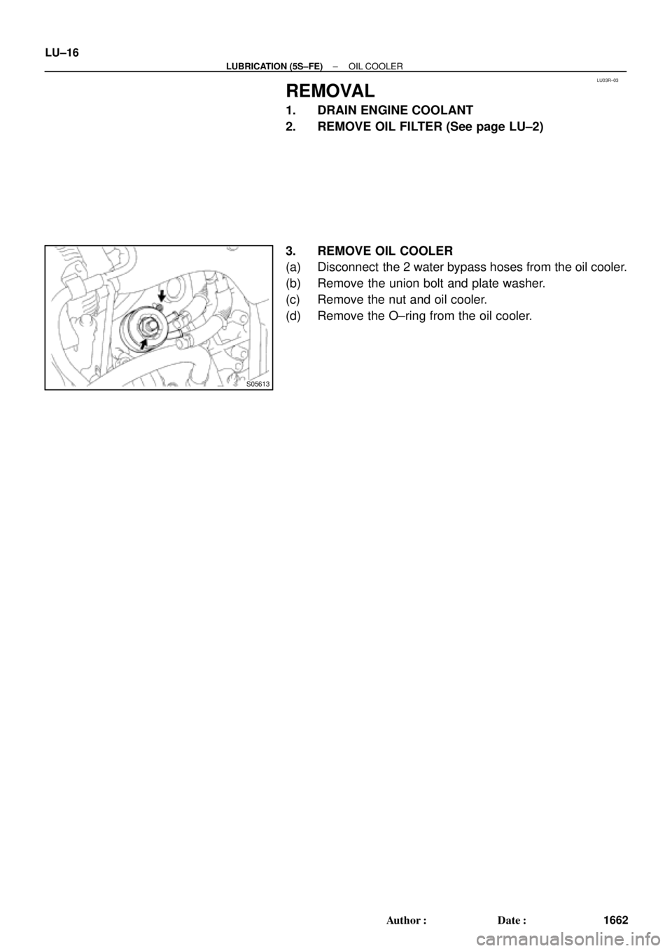
REMOVAL
1. DRAIN ENGINE COOLANT
2. REMOVE OIL FILTER (See page LU±2)
3. REMOVE OIL COOLER
(a) Disconnect the 2 water bypass hoses from the oil cooler.
(b) Remove the union bolt and plate washer.
(c) Remove the nut and oil cooler.
(d) Remove the O±ring from the oil cooler.
Page 3731 of 4770
LU03S±03
S05929
± LUBRICATION (5S±FE)OIL COOLER
LU±17
1663 Author�: Date�:
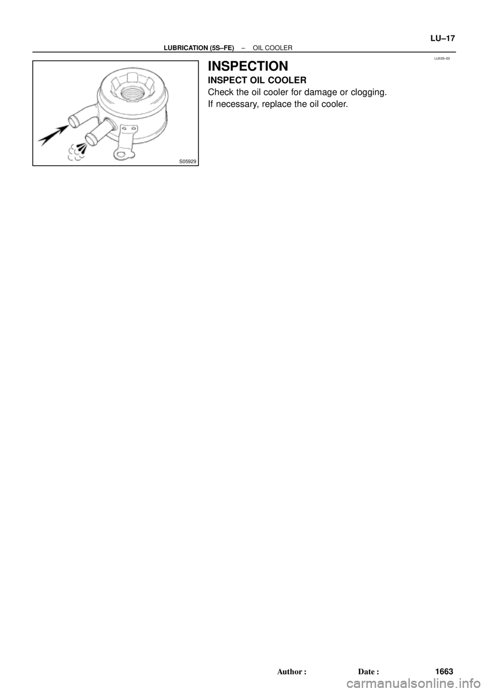
INSPECTION
INSPECT OIL COOLER
Check the oil cooler for damage or clogging.
If necessary, replace the oil cooler.
Page 3732 of 4770
LU03T±03
S05930
New
O±Ring
S05613
LU±18
± LUBRICATION (5S±FE)OIL COOLER
1664 Author�: Date�:
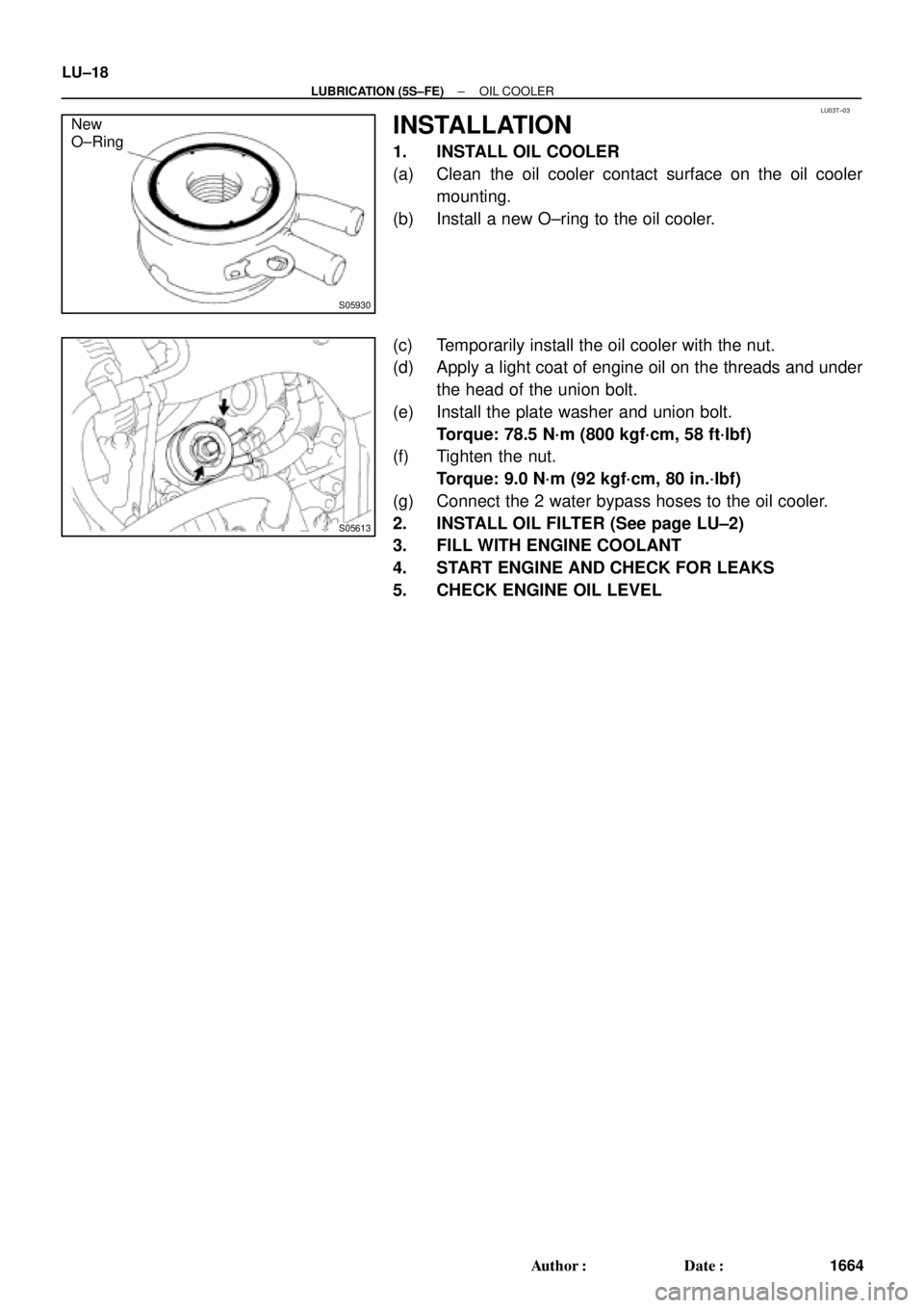
INSTALLATION
1. INSTALL OIL COOLER
(a) Clean the oil cooler contact surface on the oil cooler
mounting.
(b) Install a new O±ring to the oil cooler.
(c) Temporarily install the oil cooler with the nut.
(d) Apply a light coat of engine oil on the threads and under
the head of the union bolt.
(e) Install the plate washer and union bolt.
Torque: 78.5 N´m (800 kgf´cm, 58 ft´lbf)
(f) Tighten the nut.
Torque: 9.0 N´m (92 kgf´cm, 80 in.´lbf)
(g) Connect the 2 water bypass hoses to the oil cooler.
2. INSTALL OIL FILTER (See page LU±2)
3. FILL WITH ENGINE COOLANT
4. START ENGINE AND CHECK FOR LEAKS
5. CHECK ENGINE OIL LEVEL