Page 3650 of 4770
IGNITION SYSTEM
IG±3
1685 Author�: Date�:
(c) Using a 16 mm plug wrench, remove the 4 spark plugs.
(d) Visually check the sp")
S05308
16 mm Plug
Wrench
P20584
IG0152
B06373
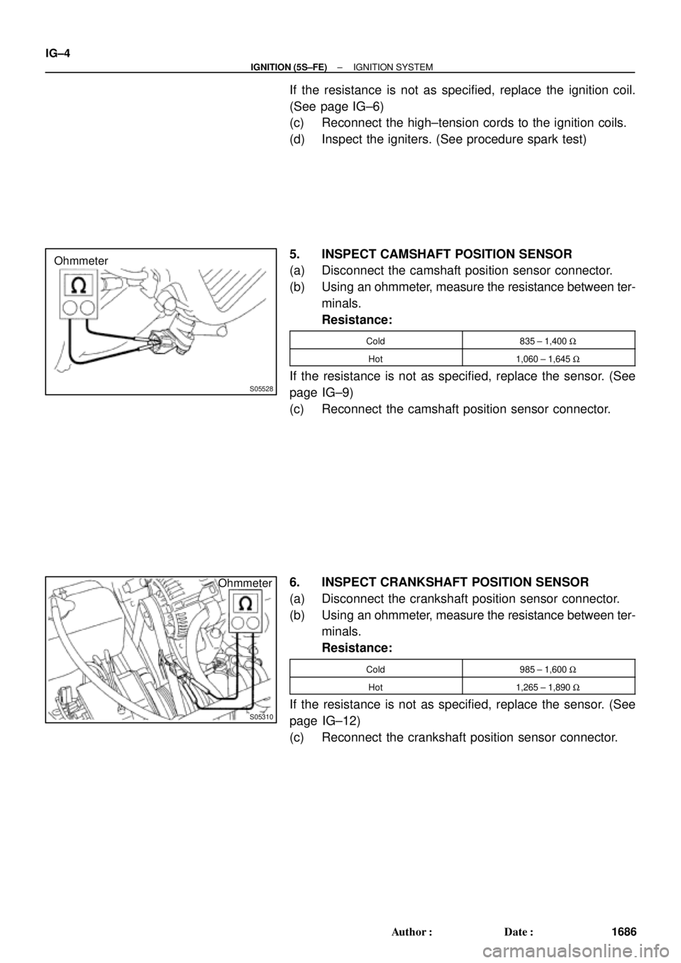
Ohmmeter
± IGNITION (5S±FE)IGNITION SYSTEM
IG±3
1685 Author�: Date�:
(c) Using a 16 mm plug wrench, remove the 4 spark plugs.
(d) Visually check the spark plug for thread damage and insu-
lator damage.
If abnormal, replace the spark plug.
Recommended spark plug:
DENSO madePK20TR11
NGK madeBKR6EKPB11
(e) Inspect the electrode gaps.
Maximum electrode gap for used spark plug:
1.3 mm (0.051 in.)
If the gap is greater than maximum, replace the spark plug.
Correct electrode gap for new spark plug:
1.1 mm (0.043 in.)
NOTICE:
If adjusting the gap of a new spark plug, bend only the base
of the ground electrode. Do not touch the tip. Never attempt
to adjust the gap on the used plug.
(f) Clean the spark plugs.
If the electrode has traces of wet carbon, allow it to dry and then
clean with a spark plug cleaner.
Air pressure: Below 588 kPa (6 kgf/cm
2, 85 psi)
Duration: 20 seconds or less
HINT:
If there are traces of oil, remove it with gasoline before using the
spark plug cleaner.
(g) Using a 16 mm plug wrench, install the 4 spark plugs.
Torque: 18 N´m (180 kgf´cm, 13 ft´lbf)
(h) Reconnect the high±tension cords from the spark plugs.
4. INSPECT IGNITION COILS WITH IGNITERS
(a) Disconnect the high±tension cords from the ignition coils.
(b) Inspect the secondary coil resistance.
Using an ohmmeter, measure the resistance between the
high±tension terminals.
Secondary coil resistance:
Cold9.7 ± 16.7 kW
Hot12.4 ± 19.6 kW
Page 3651 of 4770
S05528
Ohmmeter
S05310
Ohmmeter IG±4
± IGNITION (5S±FE)IGNITION SYSTEM
1686 Author�: Date�:
If the resistance is not as specified, replace the ignition coil.
(See page IG±6)
(c) Reconnect the high±tension cords to the ignition coils.
(d) Inspect the igniters. (See procedure spark test)
5. INSPECT CAMSHAFT POSITION SENSOR
(a) Disconnect the camshaft position sensor connector.
(b) Using an ohmmeter, measure the resistance between ter-
minals.
Resistance:
Cold835 ± 1,400 W
Hot1,060 ± 1,645 W
If the resistance is not as specified, replace the sensor. (See
page IG±9)
(c) Reconnect the camshaft position sensor connector.
6. INSPECT CRANKSHAFT POSITION SENSOR
(a) Disconnect the crankshaft position sensor connector.
(b) Using an ohmmeter, measure the resistance between ter-
minals.
Resistance:
Cold985 ± 1,600 W
Hot1,265 ± 1,890 W
If the resistance is not as specified, replace the sensor. (See
page IG±12)
(c) Reconnect the crankshaft position sensor connector.
Page 3652 of 4770
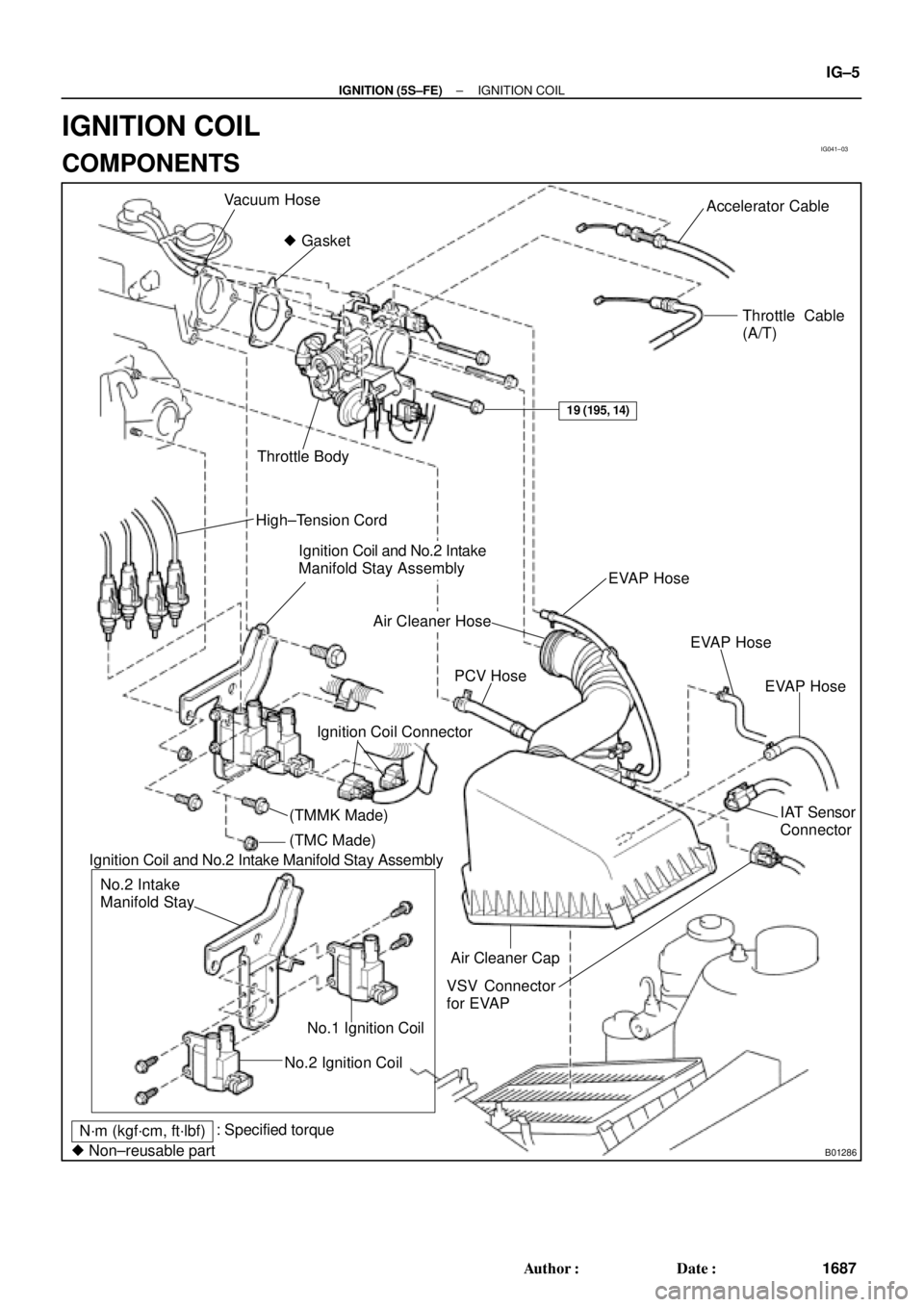
IG041±03
B01286
Vacuum Hose
� GasketAccelerator Cable
Throttle Cable
(A/T)
Throttle Body
High±Tension Cord
Ignition Coil and No.2 Intake
Manifold Stay Assembly
EVAP Hose
Air Cleaner Hose
IAT Sensor
Connector PCV Hose
VSV Connector
for EVAP
No.2 Ignition CoilNo.1 Ignition Coil No.2 Intake
Manifold Stay
N´m (kgf´cm, ft´lbf): Specified torque
� Non±reusable part
19 (195, 14)
EVAP Hose
EVAP Hose
Ignition Coil Connector
Air Cleaner Cap Ignition Coil and No.2 Intake Manifold Stay Assembly
(TMMK Made)
(TMC Made)
± IGNITION (5S±FE)IGNITION COIL
IG±5
1687 Author�: Date�:
IGNITION COIL
COMPONENTS
Page 3653 of 4770
IGNITION COIL
1688 Author�: Date�:
REPLACEMENT
1. DISCONNECT THROTTLE BODY FROM INTAKE MAN-
IFOLD (See page SF±32)
2. REMOVE IGN")
IG0DC±01
S05549
Wire
Clamp
S05604
No.1
No.2 IG±6
± IGNITION (5S±FE)IGNITION COIL
1688 Author�: Date�:
REPLACEMENT
1. DISCONNECT THROTTLE BODY FROM INTAKE MAN-
IFOLD (See page SF±32)
2. REMOVE IGNITION COILS AND NO.2 INTAKE MAN-
IFOLD STAY ASSEMBLY
(a) Disconnect the 2 ignition coil connectors.
(b) Disconnect the wire clamp from the manifold stay.
(c) TMC Made:
Remove the 2 nuts, 2 bolts, 2 ignition coils and manifold
stay assembly.
(d) TMMK Made:
Remove the nut, 3 bolts, 2 ignition coils and manifold stay
assembly.
3. REMOVE IGNITION COILS FROM NO.2 INTAKE MAN-
IFOLD STAY
Remove the 2 bolts and ignition coil. Remove the 2 ignition
coils.
4. REINSTALL IGNITION COILS TO NO.2 INTAKE MAN-
IFOLD STAY
Install the ignition coil with the 2 bolts. Install the 2 ignition coils.
Torque: 9.8 N´m (100 kgf´cm, 87 in.´lbf)
NOTICE:
The installation positions of the ignition coils are different
for No.1 and No.2.
5. REINSTALL IGNITION COILS AND NO.2 INTAKE MAN-
IFOLD STAY ASSEMBLY
(a) TMC Made:
Install the 2 ignition coils and manifold stay assembly with
the 2 nuts and 2 bolts.
(b) TMMK Made:
Install the 2 ignition coils and manifold stay assembly with
the nut and 3 bolts.
Torque:
21 N´m (214 kgf´cm, 15 ft´lbf) for 12 mm head
42 N´m (428 kgf´cm, 31 ft´lbf) for 14 mm head
(c) Install the wire clamp to the manifold stay.
(d) Connect the 2 ignition coil connectors.
Page 3654 of 4770
± IGNITION (5S±FE)IGNITION COIL
IG±7
1689 Author�: Date�:
6. REINSTALL THROTTLE BODY (See page SF±34)
Page 3659 of 4770

IG0DF±01
CHECK POWER SUPPLY OF HIGH±TENSION COIL AND IGNITER
SPARK TEST
CHECK RESISTANCE OF HIGH±TENSION CORD
Maximum resistance: 25 kW per cord
CHECK RESISTANCE OF IGNITION COIL 1. Turn ignition switch to ON.
2. Check that there is battery voltage at ignition
coil positive (+) terminal. CHECK CONNECTION OF IGNITION COIL AND IGNITER
Resistance:
Cold Hot
Secondary
10.8 ± 14.9 kW13.1 ± 17.5 kWReplace the ignition coil (s). Connect securely.
Replace the cord(s).
Check wiring between ignition switch to
ignition coil and igniter.
NO
OK OK
OKBAD
BAD
BAD
BAD
CONNECTORS
Primary
0.70 ± 0.94 W0.85 ± 1.10 W AISAN made:
Secondary
6.8 ± 11.7 kW8.6 ± 13.7 kW Primary
0.70 ± 0.94 W0.85 ± 1.10 W Diamond made:
OK
Continue to the next page
± IGNITION (1MZ±FE)IGNITION SYSTEM
IG±1
1695 Author�: Date�:
IGNITION SYSTEM
ON±VEHICLE INSPECTION
NOTICE:
ºColdº and ºHotº in these sentences express the tempera-
ture of the coils themselves. ºColdº is from ±10°C (14°F) to
50°C (122°F) and ºHotº is from 50°C (122°F) to 100°C
(212°F).
1. INSPECT IGNITER AND SPARK TEST
Check that the spark occurs.
(1) Remove the ignition coil.
(2) Remove the spark plug.
(3) Install the spark plug to the ignition coil, and connect
the ignition coil connector.
(4) Ground the spark plug.
(5) Check if spark occurs while engine is being
cranked.
NOTICE:
To prevent excess fuel being injected from the injectors
during this test, do not crank the engine for more 5 ± 10 se-
conds at a time.
If the spark does not occur, do the test as follows:
Page 3660 of 4770

Replace the camshaft position sensor.CHECK RESISTANCE OF CAMSHAFT POSITION SENSOR
Resistance: Cold Hot
835 ± 1,400 W1,060 ± 1,645 W
CHECK IGT SIGNAL FROM ECM
CHECK RESISTANCE OF CRANKSHAFT POSITION SENSOR
Resistance: Cold Hot
1,630 ± 2,740 W2,065 ± 3,225 W
TRY ANOTHER IGNITERReplace the crankshaft position sensor.
Check wiring between ECM and igniter, and
then try another ECM.
OK
OK
OKBAD
BAD
BAD
OK
Continued from the previous page
DENSO made:
Wabash made:1,690 ± 2,560 W2,145 ± 3,010 W
B00848
P24453
WRONG
CORRECT
P24457
IG±2
± IGNITION (1MZ±FE)IGNITION SYSTEM
1696 Author�: Date�:
2. INSPECT HIGH±TENSION CORDS
(a) Remove the V±bank cover.
(b) Disconnect the high±tension cords from the spark plugs.
(1) Using needle±nose pliers, disconnect the cord
clamp from the engine wire protector.
(2) Disconnect the high±tension cords from the spark
plugs.
NOTICE:
Pulling on or bending the cords may damage the conductor
inside.
(3) Disconnect the high±tension cords from the clamp.
(c) Disconnect the high±tension cords from the ignition coils.
(1) Using a screwdriver, lift up the lock claw and discon-
nect the holder from the ignition coils.
(2) Disconnect the high±tension cord at the grommet.
NOTICE:
�Pulling on or bending the cords may damage the con-
ductor inside.
�Do not wipe any of the oil from the grommet after the
high±tension cord is disconnected.
Page 3662 of 4770
IGNITION SYSTEM
1698 Author�: Date�:
(g) Connect the high±tension cords to the ignition coils")
P24458HolderGrommet
S00813
CORRECT WRONG
Clearance
IG0147
Megger
Ground
S03776
IG±4
± IGNITION (1MZ±FE)IGNITION SYSTEM
1698 Author�: Date�:
(g) Connect the high±tension cords to the ignition coils.
(1) Assemble the holder and grommet.
(2) Align the spline of the ignition coil with the spline of
the holder, and push in the cord.
NOTICE:
Check that the holder is correctly installed to the grommet
and ignition coil as shown in the illustration.
(3) Check that the lock claw of the holder is engaged by
lightly pulling the holder.
(h) Connect the high±tension cords to the spark plugs.
(i) Install the V±bank cover.
3. INSPECT SPARK PLUGS
NOTICE:
�Never use a wire brush for cleaning.
�Never attempt to adjust the electrode gap on a used
spark plug.
�Spark plugs should be replaced every 100,000 km
(60,000 miles).
(a) Remove the high±tension cords set. (See step 2)
(b) Remove the ignition coils.
(c) Inspect the electrode.
Using a megger (insulation resistance meter), measure
the insulation resistance.
Standard correct insulation resistance:
10 MW or more
If the resistance is less than specified, proceed to step (e).
HINT:
If a megger is not available, the following simple method of in-
spection provides fairly accurate results.
(d) Simple Method:
(1) Quickly race the engine to 4,000 rpm 5 times.
(2) Remove the spark plug. (See step (e))
(3) Visually check the spark plug.
If the electrode is dry ... OK
If the electrode is wet ... Proceed to step (f)
(4) Install the spark plug. (See step (i))