Page 3663 of 4770
IGNITION SYSTEM
IG±5
1699 Author�: Date�:
(e) Using a 16 mm plug wrench, remove the 6 spark plugs
from")
P13225
16 mm Plug
Wrench
P25746
DENSO PK20TR11 NGK BKR6EKPB11
P20584
IG0152
± IGNITION (1MZ±FE)IGNITION SYSTEM
IG±5
1699 Author�: Date�:
(e) Using a 16 mm plug wrench, remove the 6 spark plugs
from the RH and LH cylinder heads.
(f) Check the spark plug for thread damage and insulator
damage.
If abnormal, replace the spark plug.
Recommended spark plug:
DENSO madePK20TR11
NGK madeBKR6EKPB11
(g) Inspect the electrode gaps.
Maximum electrode gap for used spark plug:
1.3 mm (0.051 in.)
If the gap is greater than maximum, replace the spark plug.
Correct electrode gap for new spark plug:
1.1 mm (0.043 in.)
NOTICE:
If adjusting the gap of a new spark plug, bend only the base
of the ground electrode. Do not touch the tip. Never attempt
to adjust the gap on the used plug.
(h) Clean the spark plugs.
If the electrode has traces of wet carbon, allow it to dry and then
clean with a spark plug cleaner.
Air pressure: Below 588 kPa (6 kgf/cm
2, 85 psi)
Duration: 20 seconds or less
HINT:
If there are traces of oil, remove it with gasoline before using the
spark plug cleaner.
(i) Using a 16 mm plug wrench, install the 6 spark plugs to
the RH and LH cylinder heads.
Torque: 18 N´m (180 kgf´cm, 13 ft´lbf)
(j) Install the ignition coils.
(k) Install the high±tension cords set. (See step 2)
4. INSPECT IGNITION COILS
(a) Disconnect the high±tension cords from the ignition coils.
(b) Disconnect the ignition coil connectors.
Page 3664 of 4770
IGNITION SYSTEM
1700 Author�: Date�:
(c) Using an ohmmeter, measure the primary coil resistance
between the positive (+) and")
S05622
Ohmmeter
B00849
Ohmmeter
S04599
Ohmmeter IG±6
± IGNITION (1MZ±FE)IGNITION SYSTEM
1700 Author�: Date�:
(c) Using an ohmmeter, measure the primary coil resistance
between the positive (+) and negative (±) terminals.
Primary coil resistance:
Cold0.70 ± 0.94 W
Hot0.85 ± 1.10 W
If the resistance is not as specified, replace the ignition coil.
(d) Using an ohmmeter, measure the secondary coil resis-
tance between the positive (+) and high±tension terminal.
Secondary coil resistance:
AISAN madeCold10.8 ± 14.9 kW
AISAN madeHot13.1 ± 17.5 kW
Diamond madeCold6.8 ± 11.7 kW
Diamond madeHot8.6 ± 13.7 kW
If the resistance is not as specified, replace the ignition coil.
(e) Connect the ignition coil connectors.
(f) Connect the high±tension cords to the ignition coils.
5. INSPECT CAMSHAFT POSITION SENSOR
(a) Disconnect the camshaft position sensor connector.
(b) Using an ohmmeter, measure the resistance between ter-
minals.
Resistance:
DENSO madeCold835 ± 1,400 W
DENSO madeHot1,060 ± 1,645 W
Wabash madeCold1,690 ± 2,560 W
Wabash madeHot2,145 ± 3,010 W
If the resistance is not as specified, replace the camshaft posi-
tion sensor.
(c) Connect the camshaft position sensor connector.
Page 3665 of 4770
IG02I±03
S04720
± IGNITION (1MZ±FE)IGNITION COIL
IG±7
1701 Author�: Date�:
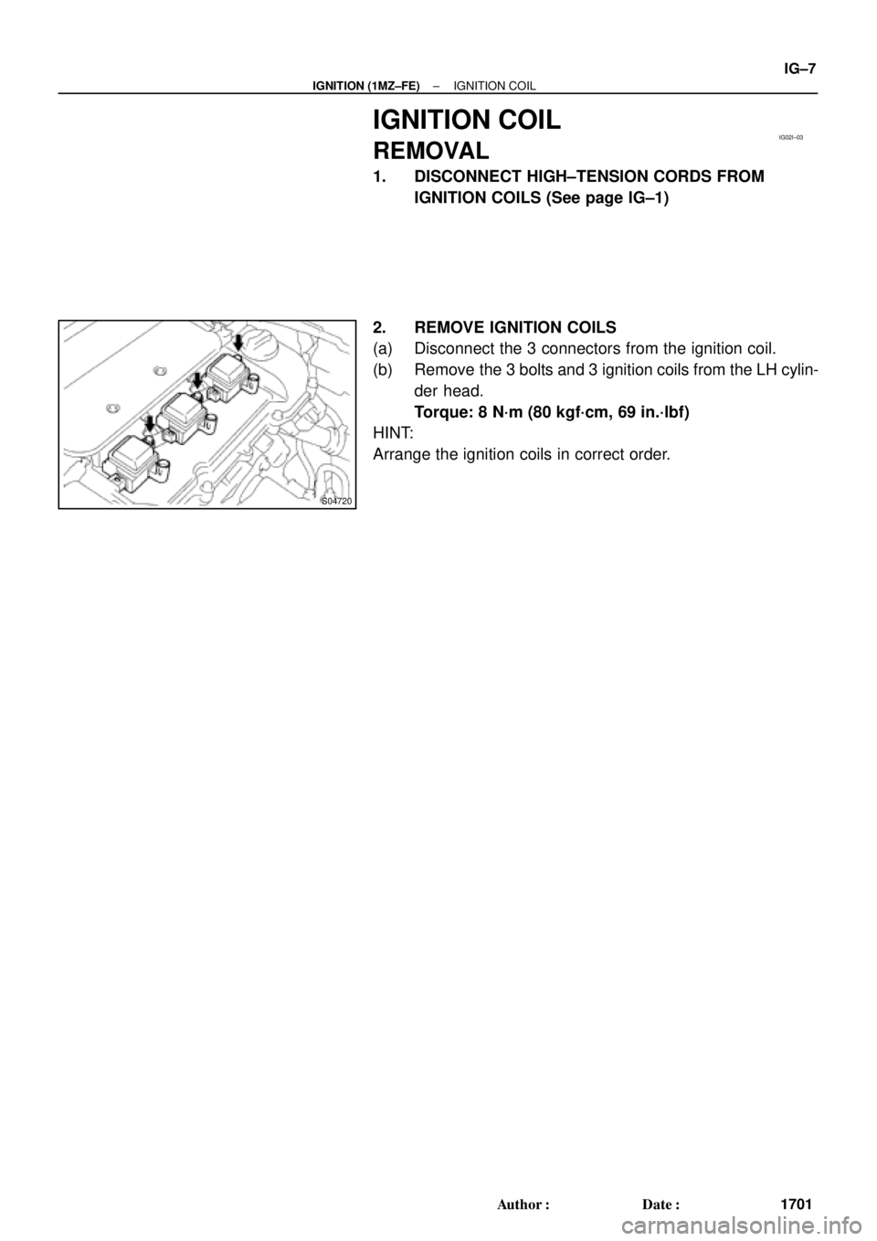
IGNITION COIL
REMOVAL
1. DISCONNECT HIGH±TENSION CORDS FROM
IGNITION COILS (See page IG±1)
2. REMOVE IGNITION COILS
(a) Disconnect the 3 connectors from the ignition coil.
(b) Remove the 3 bolts and 3 ignition coils from the LH cylin-
der head.
Torque: 8 N´m (80 kgf´cm, 69 in.´lbf)
HINT:
Arrange the ignition coils in correct order.
Page 3666 of 4770
IG02J±01
IG±8
± IGNITION (1MZ±FE)IGNITION COIL
1702 Author�: Date�:
INSTALLATION
Installation is in the reverse order of removal. (See page IG±7)
Page 3675 of 4770
 Use fender, seat and floor covers to")
FI1066
IN0CO±04
Z11554
Seal Lock Adhesive
IN±4
± INTRODUCTIONREPAIR INSTRUCTIONS
4 Author�: Date�:
REPAIR INSTRUCTIONS
GENERAL INFORMATION
BASIC REPAIR HINT
(a) Use fender, seat and floor covers to keep the vehicle
clean and prevent damage.
(b) During disassembly, keep parts in the appropriate order
to facilitate reassembly.
(c) Installation and removal of battery terminal:
(1) Before performing electrical work, disconnect the
negative (±) terminal cable from the battery.
(2) If it is necessary to disconnect the battery for in-
spection or repair, first disconnect the negative (±)
terminal cable.
(3) When disconnecting the terminal cable, to prevent
damage to battery terminal, loosen the cable nut
and raise the cable straight up without twisting or
prying it.
(4) Clean the battery terminals and cable ends with a
clean shop rag. Do not scrape them with a file or oth-
er abrasive objects.
(5) Install the cable ends to the battery terminals after
loosening the nut, and tighten the nut after installa-
tion. Do not use a hammer to tap the cable ends
onto the terminals.
(6) Be sure the cover for the positive (+) terminal is
properly in place.
(d) Check hose and wiring connectors to make sure that they
are connected securely and correctly.
(e) Non±reusable parts
(1) Always replace cotter pins, gaskets, O±rings, oil
seals, etc. with new ones.
(2) Non±reusable parts are indicated in the component
illustrations by the º�º symbol.
(f) Precoated parts
Precoated parts are bolts, nuts, etc. that are coated with
a seal lock adhesive at the factory.
(1) If a precoated part is retightened, loosened or
caused to move in any way, it must be recoated with
the specified adhesive.
(2) When reusing precoated parts, clean off the old
adhesive and dry with compressed air. Then apply
the specified seal lock adhesive to the bolt, nut or
threads.
Page 3688 of 4770

± INTRODUCTIONFOR ALL OF VEHICLES
IN±17
17 Author�: Date�:
2. FOR VEHICLES EQUIPPED WITH A CATALYTIC CONVERTER
CAUTION:
If large amount of unburned gasoline flows into the converter, it may overheat and create a fire haz-
ard. To prevent this, observe the following precautions and explain them to your customer.
(a) Use only unleaded gasoline.
(b) Avoid prolonged idling.
Avoid running the engine at idle speed for more than 20 minutes.
(c) Avoid spark jump test.
(1) Perform spark jump test only when absolutely necessary. Perform this test as rapidly as possible.
(2) While testing, never race the engine.
(d) Avoid prolonged engine compression measurement.
Engine compression tests must be done as rapidly as possible.
(e) Do not run engine when fuel tank is nearly empty.
This may cause the engine to misfire and create an extra load on the converter.
(f) Avoid coasting with ignition turned off.
(g) Do not dispose of used catalyst along with parts contaminated with gasoline or oil.
3. IF VEHICLE IS EQUIPPED WITH MOBILE COMMUNICATION SYSTEM
For vehicles with mobile communication systems such as two±way radios and cellular telephones, observe
the following precautions.
(1) Install the antenna as far as possible away from the ECU and sensors of the vehicle's electronic
system.
(2) Install the antenna feeder at least 20 cm (7.87 in.) away from the ECU and sensors of the ve-
hicle's electronic systems. For details about ECU and sensors locations, refer to the section on
the applicable component.
(3) Avoid winding the antenna feeder together with other wiring as much as possible, and also avoid
running the antenna feeder parallel with other wire harnesses.
(4) Check that the antenna and feeder are correctly adjusted.
(5) Do not install powerful mobile communications system.
Page 3715 of 4770
 :
TEMPERATURE RANGE ANTICIPATED BEFORE NEXT OIL CHANGE 10W ± 30
5W ± 30 PREFERRED
±20
°C °F020406080
±29 ±18 ±7 4 16 27100
38
LU03H±03
S05317
Curved
Tip
Ins")
B00319
Recommended Viscosity (SAE) :
TEMPERATURE RANGE ANTICIPATED BEFORE NEXT OIL CHANGE 10W ± 30
5W ± 30 PREFERRED
±20
°C °F020406080
±29 ±18 ±7 4 16 27100
38
LU03H±03
S05317
Curved
Tip
Insert
S05298
Oil Pressure Gauge
P13638
Adhesive
± LUBRICATION (5S±FE)OIL AND FILTER
LU±1
1647 Author�: Date�:
OIL AND FILTER
INSPECTION
1. CHECK ENGINE OIL QUALITY
Check the oil for deterioration, entry of water, discoloring or thin-
ning.
If the quality is visibly poor, replace the oil.
Oil grade:
API grade SJ, Energy±Conserving or ILSAC multi-
grade engine oil. SAE 5W±30 is the best choice for
your vehicle, for good fuel economy, and good start-
ing in cold weather.
2. CHECK ENGINE OIL LEVEL
After warming up the engine and then 5 minutes after the en-
gine stop, oil level should be between ºLº and ºFº of the dipstick.
If low, check for leakage and add oil up to ºFº mark.
NOTICE:
�Do not fill with engine oil above the ºFº mark.
�When inserting the oil dipstick, insert the curved tip
of the dipstick facing the same direction as the curve
of the guide.
�If the dipstick gets caught while inserting it, do not
force it in. Reconfirm the direction of the dipstick.
3. REMOVE OIL PRESSURE SWITCH AND INSTALL OIL
PRESSURE GAUGE
4. WARM UP ENGINE
Allow the engine to warm up to normal operating temperature.
5. CHECK OIL PRESSURE
Oil pressure:
At idle29 kPa (0.3 kgf/cm2, 4.3 psi) or more
At 3,000 rpm245 ± 490 kPa (2.5 ± 5.0 kgf/cm2, 36 ± 71 psi)
6. REMOVE OIL PRESSURE GAUGE AND REINSTALL
OIL PRESSURE SWITCH
(a) Remove the oil pressure gauge.
(b) Apply adhesive to 2 or 3 threads of the oil pressure switch.
Adhesive:
Part No. 08833±00080, THREE BOND 1344, LOCTITE
242 or equivalent
(c) Reinstall the oil pressure switch.
7. START ENGINE AND CHECK FOR OIL LEAKS
Page 3716 of 4770
OIL AND FILTER
1648 Author�: Date�:
REPLACEMENT
CAUTION:
�Prolonged and repeated contact with mineral oil will
result in the removal of natura")
LU03I±03
S05318
SST
S05319
LU±2
± LUBRICATION (5S±FE)OIL AND FILTER
1648 Author�: Date�:
REPLACEMENT
CAUTION:
�Prolonged and repeated contact with mineral oil will
result in the removal of natural fats from the skin,
leading to dryness, irritation and dermatitis. In addi-
tion, used engine oil contains potentially harmful
contaminants which may cause skin cancer.
�Care should be taken, therefore, when changing en-
gine oil to minimize the frequency and length of time
your skin is exposed to used engine oil. Protective
clothing and gloves that cannot be penetrated by oil
should be worn. The skin should be thoroughly
washed with soap and water, or use water±less hand
cleaner, to remove any used engine oil. Do not use
gasoline, thinners, or solvents.
�In order to preserve the environment, used oil and
used oil filters must be disposed of only at desig-
nated disposal sites.
1. DRAIN ENGINE OIL
(a) Remove the oil filler cap.
(b) Remove the oil drain plug, and drain the oil into a contain-
er.
2. REPLACE OIL FILTER
(a) Using SST, remove the oil filter.
SST 09228±06501
(b) Clean the oil filter contact surface on the oil filter mount-
ing.
(c) Lubricate the filter rubber gasket with clean engine oil.
(d) Tighten the oil filter by hand until the rubber gasket con-
tacts the seat of the filter mounting.