Page 3717 of 4770
S05320
SST
3/4
Turn
± LUBRICATION (5S±FE)OIL AND FILTER
LU±3
1649 Author�: Date�:
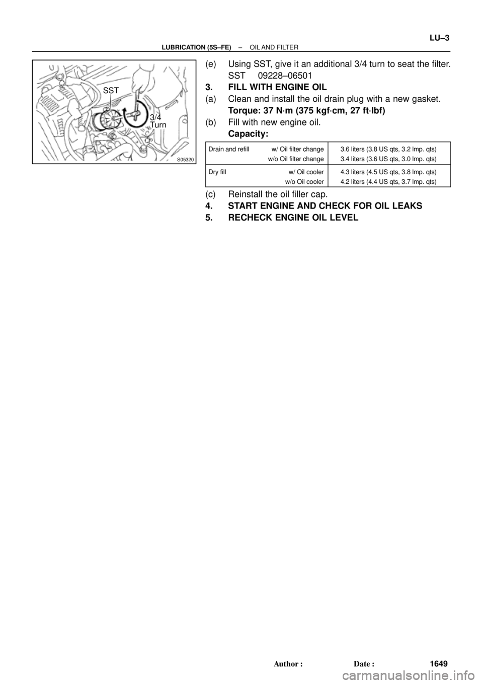
(e) Using SST, give it an additional 3/4 turn to seat the filter.
SST 09228±06501
3. FILL WITH ENGINE OIL
(a) Clean and install the oil drain plug with a new gasket.
Torque: 37 N´m (375 kgf´cm, 27 ft´lbf)
(b) Fill with new engine oil.
Capacity:
Drain and refill w/ Oil filter change
w/o Oil filter change3.6 liters (3.8 US qts, 3.2 lmp. qts)
3.4 liters (3.6 US qts, 3.0 lmp. qts)
Dry fill w/ Oil cooler
w/o Oil cooler4.3 liters (4.5 US qts, 3.8 lmp. qts)
4.2 liters (4.4 US qts, 3.7 lmp. qts)
(c) Reinstall the oil filler cap.
4. START ENGINE AND CHECK FOR OIL LEAKS
5. RECHECK ENGINE OIL LEVEL
Page 3718 of 4770
LU03J±03
S05595
Engine Moving Control Rod
No.2 RH Engine Mounting Bracket
Generator Drive Belt
RH Front Fender Apron Seal
PS Pump Drive Belt
Exhaust Pipe Bracket
Oil Pan InsulatorGround Strap Connector
No.2 Rear End Plate
No.2 Exhaust
Manifold Stay
(TMMK Made)
(TMC Made)LH Stiffener Plate
� Gasket
Bracket
Front Exhaust Pipe
StayBracket� Gasket
N´m (kgf´cm, ft´lbf): Specified torque
� Non±reusable part
64 (650, 47)
52 (530, 38)
62 (630, 46)56 (570, 41) 64 (650, 47)
��
� LU±4
± LUBRICATION (5S±FE)OIL PUMP
1650 Author�: Date�:
OIL PUMP
COMPONENTS
Page 3719 of 4770
B06345
No.2 Timing Belt Cover
No.1 Timing Belt Cover* Gasket
Wire
ClampGeneratorGenerator Wire
Generator Connector
Crankshaft Pulley
No.2 Idler Pulley
Oil Pump Pulley
Crankshaft
Timing Pulley
Crankshaft Position SensorTiming Belt Guide
Wire ClampWire
Clamp
Timing Belt
Clamp
No.1 Idler Pulley
Tension Spring � GasketClamp
� Gasket
� GasketHigh±Tension Cord
Spark Plug
Oil Strainer
Drain Plug
N´m (kgf´cm, ft´lbf): Specified torque
� Non±reusable partx 17
* Gasket
* Replace only if damagedOil Pump
x 10
8.8 (90, 78 in.´lbf)5.4 (55, 48 in.´lbf)
5.4 (55, 48 in.´lbf)
24 (245, 18)
42 (425, 31)
108 (1,100, 80)
18 (180, 13)
42 (425, 31)
Oil Pan
± LUBRICATION (5S±FE)OIL PUMP
LU±5
1651 Author�: Date�:
Page 3720 of 4770
Z19079
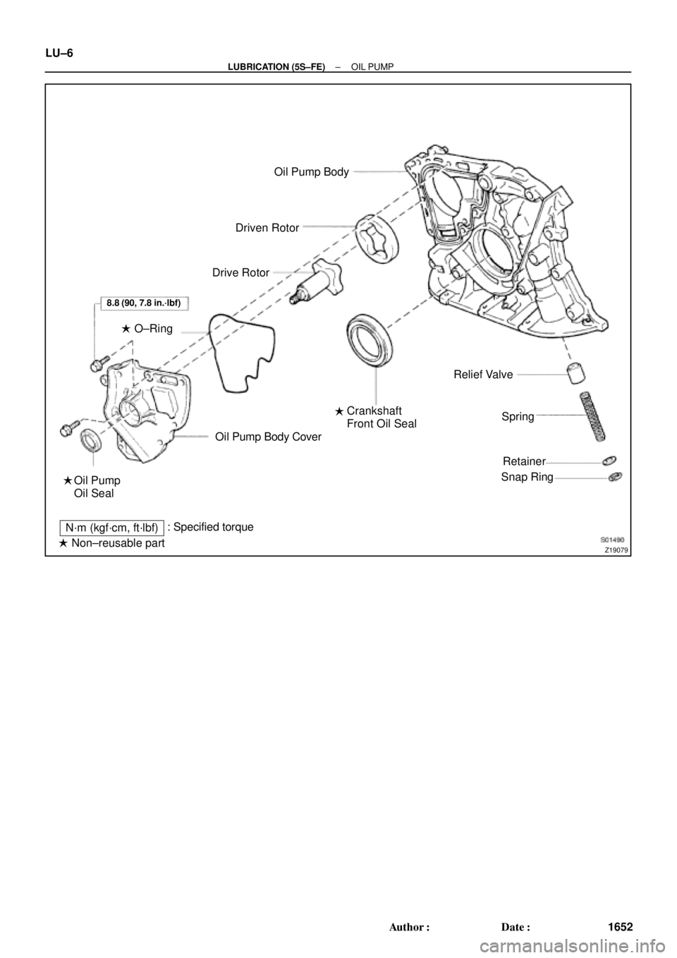
Oil Pump Body
Driven Rotor
Drive Rotor
Oil Pump Body Cover
Oil Pump
Oil SealCrankshaft
Front Oil SealRelief Valve
Spring
Retainer
Snap Ring
N´m (kgf´cm, ft´lbf): Specified torque
� Non±reusable part ��
8.8 (90, 7.8 in.´lbf)
� O±Ring LU±6
± LUBRICATION (5S±FE)OIL PUMP
1652 Author�: Date�:
Page 3721 of 4770
OIL PUMP
LU±7
1653 Author�: Date�:
REMOVAL
HINT:
When repairing the oil pump, the oil pan and strainer should be
removed and cleaned.
1.")
LU03K±03
S05311
S05952
SST
SST
S05928
± LUBRICATION (5S±FE)OIL PUMP
LU±7
1653 Author�: Date�:
REMOVAL
HINT:
When repairing the oil pump, the oil pan and strainer should be
removed and cleaned.
1. DRAIN ENGINE OIL
2. REMOVE FRONT EXHAUST PIPE (See page EM±69)
3. REMOVE NO.2 EXHAUST MANIFOLD STAY AND LH
STIFFENER PLATE (See page EM±69)
4. REMOVE EXHAUST PIPE BRACKET, OIL PAN INSU-
LATOR AND NO.2 REAR END PLATE
(See page EM±69)
5. REMOVE OIL PAN
(a) Remove the oil dipstick.
(b) Remove the 17 bolts and 2 nuts.
(c) Insert the blade of SST between the cylinder block and oil
pan, and cut off applied sealer and remove the oil pan.
SST 09032±00100
NOTICE:
�Do not use SST for the oil pump body side and rear oil
seal retainer.
�Be careful not to damage the oil pan flange.
6. REMOVE OIL STRAINER
Remove the bolt, 2 nuts, oil strainer and gasket.
7. REMOVE TIMING BELT (See page EM±17)
8. REMOVE NO.2 IDLER PULLEY
Remove the bolt and idler pulley.
9. REMOVE CRANKSHAFT TIMING PULLEY
(See page EM±17)
10. REMOVE OIL PUMP PULLEY (See page EM±17)
Page 3722 of 4770
S05607
LU±8
± LUBRICATION (5S±FE)OIL PUMP
1654 Author�: Date�:
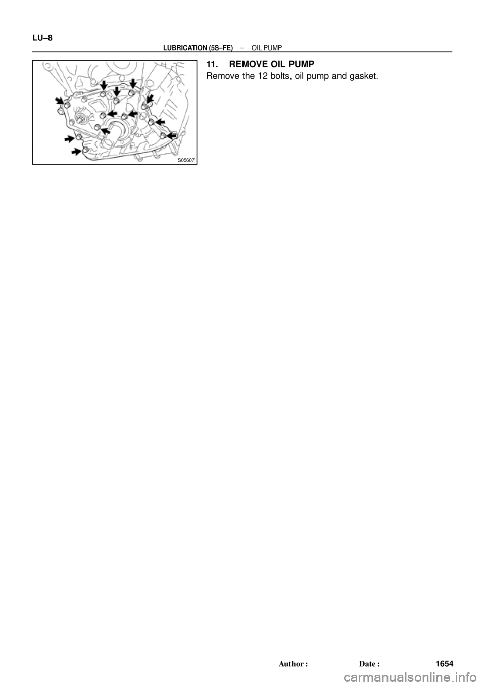
11. REMOVE OIL PUMP
Remove the 12 bolts, oil pump and gasket.
Page 3723 of 4770
LU03L±03
S01168
S01169
± LUBRICATION (5S±FE)OIL PUMP
LU±9
1655 Author�: Date�:
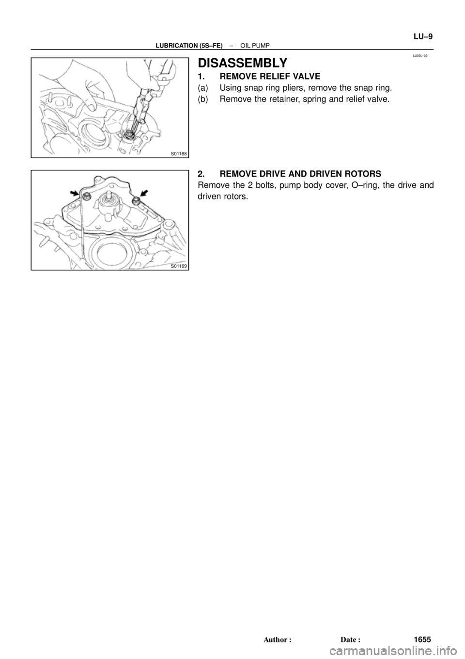
DISASSEMBLY
1. REMOVE RELIEF VALVE
(a) Using snap ring pliers, remove the snap ring.
(b) Remove the retainer, spring and relief valve.
2. REMOVE DRIVE AND DRIVEN ROTORS
Remove the 2 bolts, pump body cover, O±ring, the drive and
driven rotors.
Page 3724 of 4770
OIL PUMP
1656 Author�: Date�:
INSPECTION
1. INSPECT RELIEF VALVE
Coat the valve with engine oil and check that it falls smoothly
into the v")
LU03M±03
S01170
S01483
S01484
LU±10
± LUBRICATION (5S±FE)OIL PUMP
1656 Author�: Date�:
INSPECTION
1. INSPECT RELIEF VALVE
Coat the valve with engine oil and check that it falls smoothly
into the valve hole by its own weight.
If it doesn't, replace the relief valve. If necessary, replace the oil
pump assembly.
2. INSPECT DRIVE AND DRIVEN ROTORS
(a) Inspect the rotors for body clearance.
Using a feeler gauge, measure the clearance between
the driven rotor and body.
Standard body clearance:
0.10 ± 0.16 mm (0.0039 ± 0.0063 in.)
Maximum body clearance: 0.20 mm (0.0079 in.)
If the body clearance is greater than maximum, replace the ro-
tors as a set. If necessary, replace the oil pump assembly.
(b) Inspect the rotors for tip clearance.
Using a feeler gauge, measure the clearance between
the drive and driven rotor tips.
Standard tip clearance:
0.04 ± 0.16 mm (0.0016 ± 0.0063 in.)
Maximum tip clearance: 0.20 mm (0.0079 in.)
If the tip clearance is greater than maximum, replace the rotors
as a set.