Page 3764 of 4770
MANUAL TRANSAXLE UNIT
MX±5
1855 Author�: Date�:
10. REMOVE 4 TRANSAXLE UPPER SIDE")
Q10002
14 mm Head
17 mm Head
Q10003
Oil Level
Filler Plug
Drain Plug0 ± 5 mm
Q10010
Q10004
± MANUAL TRANSAXLE (S51)MANUAL TRANSAXLE UNIT
MX±5
1855 Author�: Date�:
10. REMOVE 4 TRANSAXLE UPPER SIDE MOUNTING
BOLTS
Torque:
17 mm head: 64 N´m (650 kgf´cm, 47 ft´lbf)
14 mm head: 46 N´m (470 kgf´cm, 34 ft´lbf)
11. REMOVE FRONT WHEEL
Torque: 103 N´m (1,050 kgf´cm, 76 ft´lbf)
12. RAISE VEHICLE
NOTICE:
Make sure that the vehicle is securely supported.
13. REMOVE ENGINE REAR SIDE SHUTTER PLATE AND
LH AND RH FENDER APRON SEALS
14. DRAIN TRANSAXLE OIL
Oil grade: API GL±4 or GL±5
Viscosity: SAE 75W±90
Capacity: 2.6 liters (2.7 US qts, 2.3 Imp. qts)
Torque: 49 N´m (500 kgf´cm, 36 ft´lbf)
15. REMOVE LH AND RH DRIVE SHAFTS
(See page SA±16)
16. REMOVE FRONT EXHAUST PIPE
(a) Remove the 2 bolts, nut and exhaust pipe bracket.
Torque:
Bolt: 19 N´m (195 kgf´cm, 14 ft´lbf)
Nut: 33 N´m (330 kgf´cm, 24 ft´lbf)
(b) Remove the 3 nuts and gasket from the exhaust manifold.
Torque: 62 N´m (630 kgf´cm, 46 ft´lbf)
(c) Remove the 2 bolts, nuts and gasket.
Torque: 56 N´m (570 kgf´cm, 41 ft´lbf)
(d) Remove the 2 set bolts of the No.1 exhaust pipe support
bracket.
Torque: 33 N´m (330 kgf´cm, 24 ft´lbf)
(e) Remove the front exhaust pipe.
Page 3766 of 4770
MANUAL TRANSAXLE UNIT
MX±7
1857 Author�: Date�:
23. REMOVE FRONT SUSPENSION MEMBER WITH LOW-
ER SUSPENSION ARM
(a) Remove the LH and RH f")
Q10008
C
C
A
CBA
ABC A
Q10011
Q10009
± MANUAL TRANSAXLE (S51)MANUAL TRANSAXLE UNIT
MX±7
1857 Author�: Date�:
23. REMOVE FRONT SUSPENSION MEMBER WITH LOW-
ER SUSPENSION ARM
(a) Remove the LH and RH fender liner set screws.
(b) Remove the 6 bolts, 4 nuts, front LH and RH suspension
member braces, rear LH and RH suspension member
braces and front suspension member with the lower sus-
pension arm.
Torque:
Bolt A: 181 N´m (1,850 kgf´cm, 134 ft´lbf)
Bolt B: 32 N´m (330 kgf´cm, 24 ft´lbf)
Nut C: 36 N´m (370 kgf´cm, 27 ft´lbf)
24. JACK UP TRANSAXLE SLIGHTLY
Using a transmission jack, support the transaxle.
25. REMOVE LH STIFFENER PLATE
Remove the 3 bolts and LH stiffener plate.
Torque: 37 N´m (380 kgf´cm, 27 ft´lbf)
26. REMOVE REAR END PLATE WITH OIL PAN INSULA-
TOR AND RH STIFFENER PLATE
(a) Remove the 2 bolts and rear end plate with the oil pan in-
sulator.
Torque: 9.3 N´m (95 kgf´cm, 82 in.´lbf)
(b) Remove the 2 bolts and manifold stay.
Torque: 39 N´m (400 kgf´cm, 29 ft´lbf)
(c) Remove the 4 bolts and RH stiffener plate.
Torque: 39 N´m (400 kgf´cm, 29 ft´lbf)
27. REMOVE TRANSAXLE
Lower the engine left side and remove the transaxle from the
engine.
HINT:
At the time of installation, please refer to the following items.
�Align the input shaft with the clutch disc and install the
transaxle to the engine.
�Temporarily tighten the transaxle mounting bolts.
Page 3769 of 4770
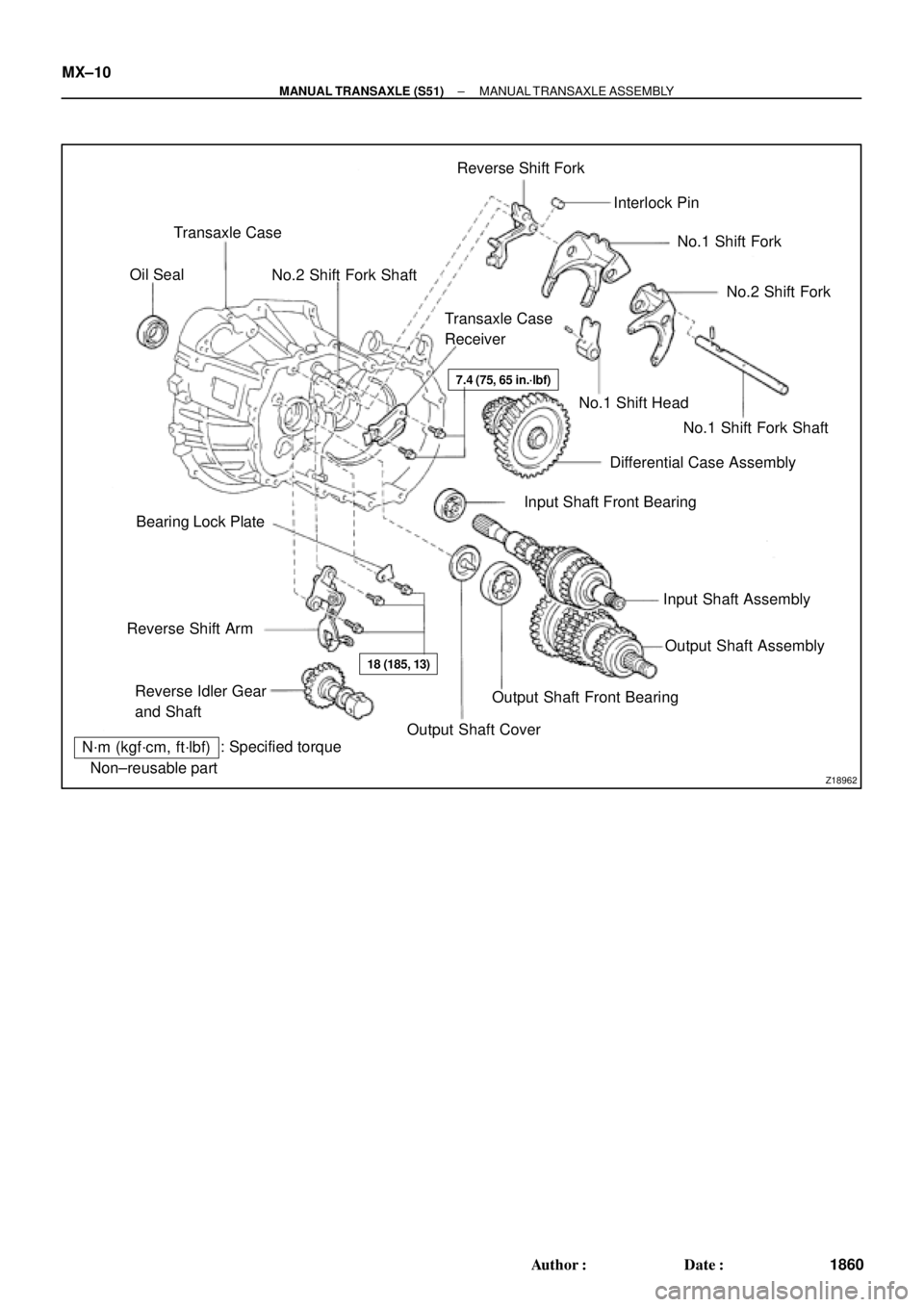
Z18962�Non±reusable part: Specified torque
N´m (kgf´cm, ft´lbf)Transaxle Case
No.2 Shift Fork ShaftReverse Shift Fork
Interlock Pin
No.1 Shift Fork
No.1 Shift Fork Shaft No.1 Shift Head
Differential Case Assembly
Input Shaft Front Bearing
Input Shaft Assembly
Output Shaft CoverOutput Shaft Front Bearing Reverse Idler Gear
and Shaft Reverse Shift ArmBearing Lock PlateTransaxle Case
Receiver Oil Seal
No.2 Shift Fork
Output Shaft Assembly �
�
�
7.4 (75, 65 in.´lbf)
18 (185, 13)
MX±10
± MANUAL TRANSAXLE (S51)MANUAL TRANSAXLE ASSEMBLY
1860 Author�: Date�:
Page 3777 of 4770
MANUAL TRANSAXLE ASSEMBLY
1868 Author�: Date�:
(c) Using SST, press in a new bearing.
SST 09310±35010
(d)")
Z00593
SSTSST
Front
Z00413
SST0 ± 0.5mm
Z00596
13.5 ± 0.5mm MX±18
± MANUAL TRANSAXLE (S51)MANUAL TRANSAXLE ASSEMBLY
1868 Author�: Date�:
(c) Using SST, press in a new bearing.
SST 09310±35010
(d) Install the bearing lock plate and torque the bolt.
Torque: 18 N´m (185 kgf´cm, 13 ft´lbf)
5. IF NECESSARY, REPLACE INPUT SHAFT FRONT OIL
SEAL
(a) Using a screwdriver, pry out the oil seal.
(b) Using SST, drive in a new oil seal.
SST 09608±00081, 09950±70010 (09951±07150)
Drive in depth:
0 ± 0.5 mm (0 ± 0.020 in.)
(c) Coat the lip of the oil seal with MP grease.
6. IF NECESSARY, REPLACE REVERSE RESTRICT PIN
(a) Using a hexagon wrench, remove the straight screw plug.
(b) Using a pin punch and hammer, drive out the slotted
spring pin.
(c) Replace the reverse restrict pin.
(d) Using a pin punch and hammer, drive in the slotted spring
pin.
Drive in depth:
13.5 ± 0.5 mm (0.531 ± 0.020 in.)
(e) Apply sealant to the plug threads.
Sealant:
Part No.08833 ± 00080, THREE BOND 1344, LOCTITE
242 or equivalent
(f) Using a hexagon wrench, install and torque the straight
screw plug.
Torque: 13 N´m (130 kgf´cm, 9 ft´lbf)
Page 3778 of 4770
MX04I±01
± MANUAL TRANSAXLE (S51)MANUAL TRANSAXLE ASSEMBLY
MX±19
1869 Author�: Date�:
REASSEMBLY
Reassembly is in the reverse order of disassembly (See page MX±11).
HINT:
Coat all of the sliding and rotating surfaces with gear oil before reassembly.
Page 3784 of 4770
INPUT SHAFT
MX±25
1875 Author�: Date�:
REASSEMBLY
HINT:
Coat all of the sliding and rotating surfaces with gear oil before
r")
MX04M±01
SM0282
Engine
Side
SM0193
Z00419
Z00604
± MANUAL TRANSAXLE (S51)INPUT SHAFT
MX±25
1875 Author�: Date�:
REASSEMBLY
HINT:
Coat all of the sliding and rotating surfaces with gear oil before
reassembly.
1. INSTALL NO.2 CLUTCH HUB INTO HUB SLEEVE
(a) Install the clutch hub and shifting keys to the hub sleeve.
(b) Install the shifting key springs under the shifting keys.
NOTICE:
Position the key springs so that their end gaps are not
aligned.
2. INSTALL 3RD GEAR, NEEDLE ROLLER BEARING,
SYNCHRONIZER RING AND NO.2 HUB SLEEVE AS-
SEMBLY TO INPUT SHAFT
(a) Apply gear oil to the needle roller bearings.
(b) Place the synchronizer ring (for the 3rd gear) on the gear
and align the ring slots with the shifting keys.
NOTICE:
Do not install the synchronizer ring for 4th gear.
(c) Using a press, install the 3rd gear and No.2 hub sleeve.
3. INSTALL SNAP RING
(a) Select a snap ring that allows the minimum axial play.
MarkThickness mm (in.)
11.95±2.00 (0.0768±0.0787)
22.00±2.05 (0.0787±0.0807)
32.05±2.10 (0.0807±0.0827)
42.10±2.15 (0.0827±0.0846)
52.15±2.20 (0.0846±0.0866)
62.20±2.25 (0.0866±0.0886)
Page 3785 of 4770
SM0189
SM0190
SM0049
SST
SM0050
MX±26
± MANUAL TRANSAXLE (S51)INPUT SHAFT
1876 Author�: Date�:
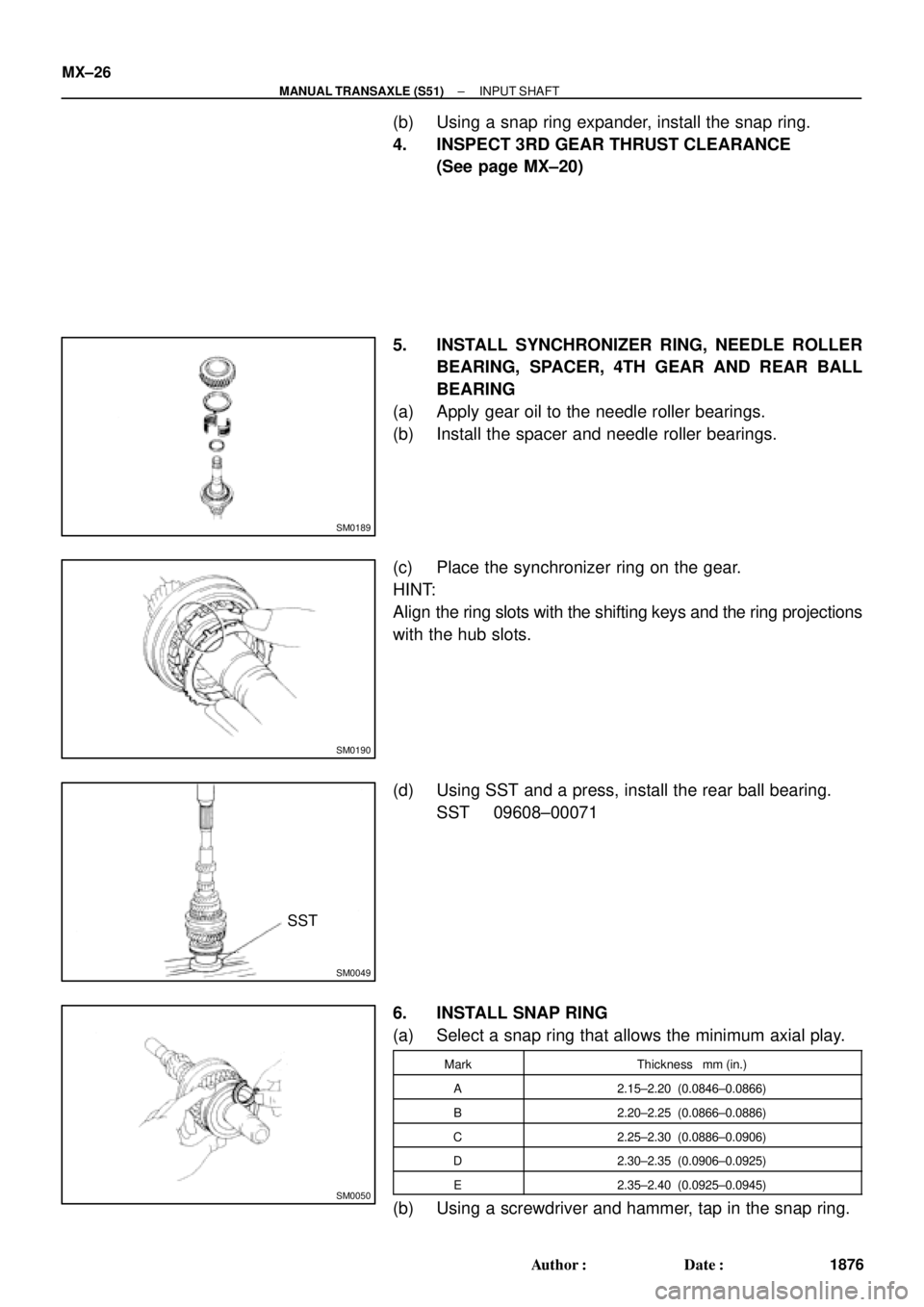
(b) Using a snap ring expander, install the snap ring.
4. INSPECT 3RD GEAR THRUST CLEARANCE
(See page MX±20)
5. INSTALL SYNCHRONIZER RING, NEEDLE ROLLER
BEARING, SPACER, 4TH GEAR AND REAR BALL
BEARING
(a) Apply gear oil to the needle roller bearings.
(b) Install the spacer and needle roller bearings.
(c) Place the synchronizer ring on the gear.
HINT:
Align the ring slots with the shifting keys and the ring projections
with the hub slots.
(d) Using SST and a press, install the rear ball bearing.
SST 09608±00071
6. INSTALL SNAP RING
(a) Select a snap ring that allows the minimum axial play.
MarkThickness mm (in.)
A2.15±2.20 (0.0846±0.0866)
B2.20±2.25 (0.0866±0.0886)
C2.25±2.30 (0.0886±0.0906)
D2.30±2.35 (0.0906±0.0925)
E2.35±2.40 (0.0925±0.0945)
(b) Using a screwdriver and hammer, tap in the snap ring.
Page 3792 of 4770
MX04Q±01
Q02949
Front
SM0199
SST
Z00428
Z00429
± MANUAL TRANSAXLE (S51)OUTPUT SHAFT
MX±33
1883 Author�: Date�:
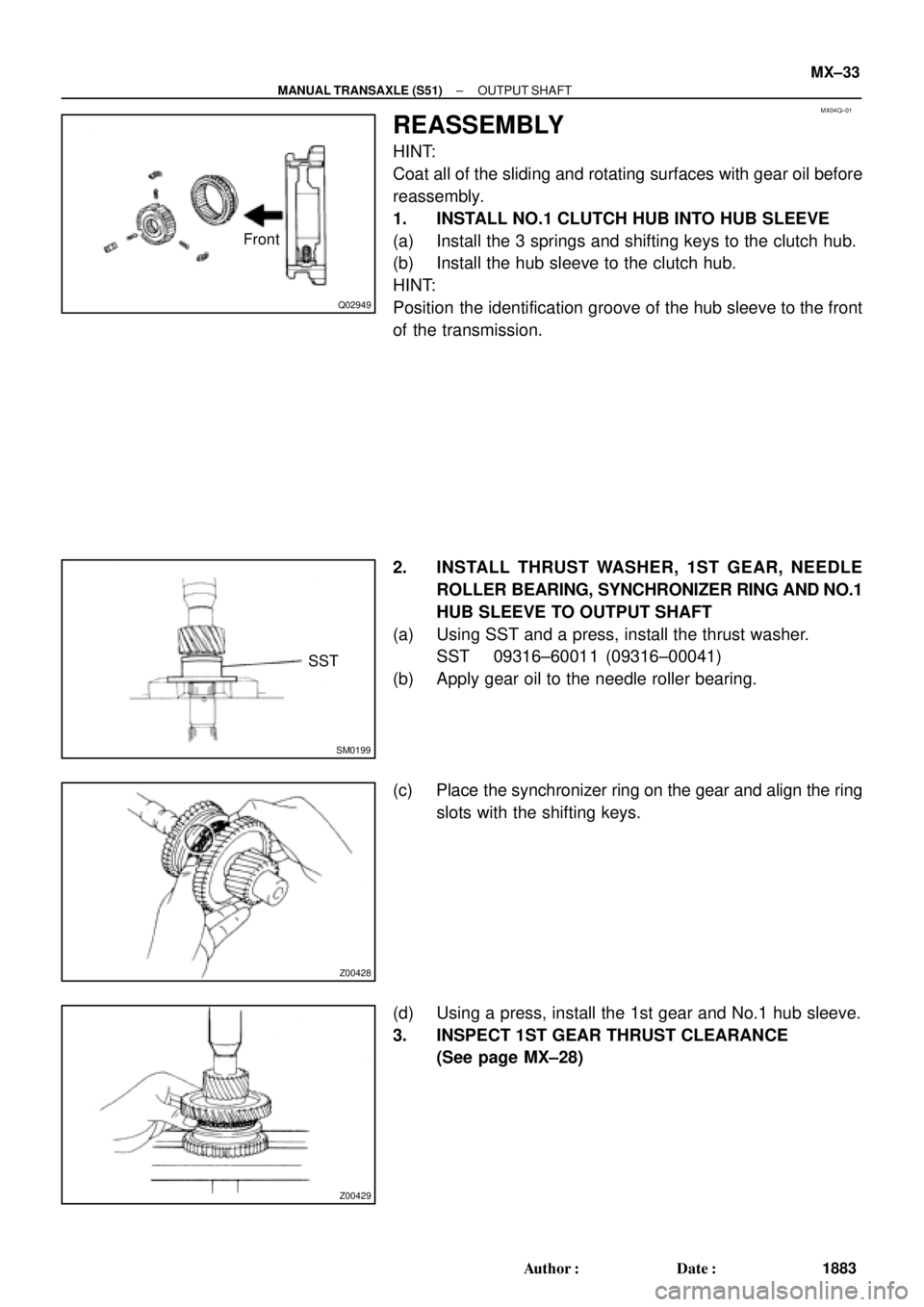
REASSEMBLY
HINT:
Coat all of the sliding and rotating surfaces with gear oil before
reassembly.
1. INSTALL NO.1 CLUTCH HUB INTO HUB SLEEVE
(a) Install the 3 springs and shifting keys to the clutch hub.
(b) Install the hub sleeve to the clutch hub.
HINT:
Position the identification groove of the hub sleeve to the front
of the transmission.
2. INSTALL THRUST WASHER, 1ST GEAR, NEEDLE
ROLLER BEARING, SYNCHRONIZER RING AND NO.1
HUB SLEEVE TO OUTPUT SHAFT
(a) Using SST and a press, install the thrust washer.
SST 09316±60011 (09316±00041)
(b) Apply gear oil to the needle roller bearing.
(c) Place the synchronizer ring on the gear and align the ring
slots with the shifting keys.
(d) Using a press, install the 1st gear and No.1 hub sleeve.
3. INSPECT 1ST GEAR THRUST CLEARANCE
(See page MX±28)