Page 3818 of 4770
MANUAL TRANSAXLE ASSEMBLY
1817 Author�: Date�:
19. REMOVE TRANSMISSION CASE
Remove the 17 bolts and tap the case")
Q05815
FIPG
MT0669
MT0693
SST
Q06375
Z17557
Matchmarks MX±16
± MANUAL TRANSAXLE (E153)MANUAL TRANSAXLE ASSEMBLY
1817 Author�: Date�:
19. REMOVE TRANSMISSION CASE
Remove the 17 bolts and tap the case with a plastic hammer.
FIPG:
Part No. 08826 ± 00090, THREE BOND 1281 or equiva-
lent
Torque: 29 N´m (300 kgf´cm, 22 ft´lbf)
20. REMOVE SHIM
HINT:
At the time of reassembly, please refer to the following item.
Install the previously selected shim by adjusting output shaft
preload.
(See page MX±22)
21. REMOVE OUTPUT SHAFT REAR TAPER ROLLER
BEARING OUTER RACE
Using SST and a hammer, remove the output shaft rear taper
roller bearing outer race.
SST 09316±60011 (09316±00011)
22. REMOVE TRANSMISSION OIL PIPE
(a) Remove the gasket from the oil pipe.
(b) Remove the 2 bolts and oil pipe.
Torque: 17 N´m (175 kgf´cm, 13 ft´lbf)
23. REMOVE REVERSE SHIFT ARM BRACKET AS-
SEMBLY
Remove the bolt and pull off the reverse shift arm and bracket.
Torque: 17 N´m (175 kgf´cm, 13 ft´lbf)
24. REMOVE REVERSE IDLER GEAR AND SHAFT
Pull out the shaft, and remove the reverse idler gear and thrust
washer.
HINT:
At the time of reassembly, please refer to the following item.
Align the matchmarks, as shown.
Page 3820 of 4770
MANUAL TRANSAXLE ASSEMBLY
1819 Author�: Date�:
32. REMOVE INPUT AND OUTPUT SHAFTS ASSEMBLY
(a) Leaning the output shaft to the differential side, remove
the inp")
MT0781
MX±18
± MANUAL TRANSAXLE (E153)MANUAL TRANSAXLE ASSEMBLY
1819 Author�: Date�:
32. REMOVE INPUT AND OUTPUT SHAFTS ASSEMBLY
(a) Leaning the output shaft to the differential side, remove
the input shaft assembly.
(b) Lift up the differential case assembly, remove the output
shaft assembly.
33. REMOVE DIFFERENTIAL CASE ASSEMBLY
(a) Remove the oil pump drive gear.
(b) Remove the differential case assembly.
34. REMOVE MAGNET FROM TRANSAXLE CASE
35. REMOVE TRANSMISSION OIL PUMP ASSEMBLY
AND OIL PIPE
(a) Remove the 2 bolts and oil pipe.
Torque: 17 N´m (175 kgf´cm, 13 ft´lbf)
(b) Remove the 2 bolts and oil pump assembly.
Torque: 17 N´m (175 kgf´cm, 13 ft´lbf)
36. REMOVE NO.5 SYNCHRONIZER RING WITH KEY
SPRING FROM NO.3 CLUTCH HUB
(a) Remove the No.5 synchronizer ring with the key spring
from the No.3 clutch hub.
(b) Using a screwdriver, remove the snap ring.
HINT:
Wrap vinyl tape on the screwdriver to prevent damaging the
synchronizer ring.
(c) Remove the synchronizer rings.
Page 3821 of 4770
MANUAL TRANSAXLE ASSEMBLY
MX±19
1820 Author�: Date�:
INSPECTION
1. INSPECT NO.5 SYNCHRONIZER RING
(a) Check for wear")
MX054±01
MT0782
WM0066
Z00192
SST
Z00194
SST
Q08014
SST
± MANUAL TRANSAXLE (E153)MANUAL TRANSAXLE ASSEMBLY
MX±19
1820 Author�: Date�:
INSPECTION
1. INSPECT NO.5 SYNCHRONIZER RING
(a) Check for wear or damage.
(b) Check the braking effect of the synchronizer ring. Turn the
middle No.5 synchronizer ring in one direction while push-
ing it to the outer No.5 synchronizer ring. Check that the
ring locks.
If it does not lock, replace the synchronizer ring.
2. MEASURE SHIFT FORK AND HUB SLEEVE CLEAR-
ANCE
Using a feeler gauge, measure the clearance between the hub
sleeve and shift fork.
Maximum clearance:
1.0 mm (0.039 in.)
If the clearance exceeds the maximum, replace the shift fork or
hub sleeve.
3. IF NECESSARY, REPLACE INPUT SHAFT BEARING
AND OIL SEAL
(a) Remove the 3 bolts and transaxle case receiver.
(b) Using SST, pull out the bearing.
SST 09612±65014
(c) Using a screwdriver, remove the oil seal.
(d) Using SST, drive in a new oil seal.
SST 09608±00081, 09950±70010 (09951±07150)
(e) Coat the lip of seal with MP grease.
(f) Using SST, drive in a new bearing.
SST 09950±60010 (09951±00580), 09950±70010
(09951±07150)
(g) Install the transaxle case receiver.
(h) Install and torque the 3 bolts.
Torque: 7.4 N´m (75 kgf´cm, 65 in.´lbf)
Page 3824 of 4770
MANUAL TRANSAXLE ASSEMBLY
1823 Author�: Date�:
REASSEMBLY
Reassembly is in the reverse order of disassembly.
HINT:
�Before reassembly, select a shim by adjus")
MX055±01
MX±22
± MANUAL TRANSAXLE (E153)MANUAL TRANSAXLE ASSEMBLY
1823 Author�: Date�:
REASSEMBLY
Reassembly is in the reverse order of disassembly.
HINT:
�Before reassembly, select a shim by adjusting output
shaft preload.
�Coat all of the sliding and rotating surfaces with gear oil
before reassembly.
ADJUST OUTPUT SHAFT PRELOAD
(a) Install the output shaft assembly to the transaxle case.
(b) Install the transmission case to the transaxle case.
HINT:
If necessary, tap on the case with a plastic hammer.
(c) Install and torque the 17 bolts.
Torque: 29 N´m (300 kgf´cm, 22 ft´lbf)
(d) Install the output shaft rear taper roller bearing outer race.
(e) Install the adjusting shim.
HINT:
When reusing the output shaft bearing, first install a shim of the
same thickness as before. If installing a new taper roller bear-
ing, first select and install a shim of lesser thickness than be-
fore.
(f) Install the rear bearing retainer.
(g) Using a torx wrench (T45), install and torque the 7 torx
screws.
Torque: 42 N´m (430 kgf´cm, 31 ft´lbf)
(h) Install a new lock nut to the output shaft.
(i) Turn the output shaft right and left 2 or 3 times to allow the
bearing to settle.
Page 3831 of 4770
INPUT SHAFT
MX±29
1830 Author�: Date�:
REASSEMBLY
HINT:
Coat all of the sliding and rotating surfaces with gear oil before
rea")
MX059±02
Q00383
Front
MT0790
Q00183SST
Q00116
± MANUAL TRANSAXLE (E153)INPUT SHAFT
MX±29
1830 Author�: Date�:
REASSEMBLY
HINT:
Coat all of the sliding and rotating surfaces with gear oil before
reassembly.
1. INSTALL NO.2 CLUTCH HUB INTO HUB SLEEVE
(a) Install the 3 springs and shifting keys to the clutch hub.
(b) Install the hub sleeve to the clutch hub.
HINT:
Direct identification groove of the hub sleeve to front of the
transmission.
2. INSTALL NEEDLE ROLLER BEARING, 3RD GEAR,
SYNCHRONIZER RING AND NO.2 HUB SLEEVE AS-
SEMBLY TO INPUT SHAFT
(a) Apply MP grease to the needle roller bearing.
(b) Assemble the needle roller bearings into the 3rd gear.
(c) Place the synchronizer rings on the gear and align the
ring slots with the shifting keys.
(d) Using SST and a press, install the 3rd gear and No.2 hub
sleeve.
SST 09506±35010
3. INSTALL SNAP RING
(a) Select a snap ring that allows the minimum axial play.
MarkThickness mm (in.)MarkThickness mm (in.)
H2.30 (0.0906)M2.50 (0.0984)
J2.35 (0.0925)N2.55 (0.1004)
K2.40 (0.0945)P2.60 (0.1024)
L2.45 (0.0965)±±
(b) Using a screwdriver and hammer, tap in the snap ring.
Page 3838 of 4770
OUTPUT SHAFT
1837 Author�: Date�:
REASSEMBLY
HINT:
Coat all of the sliding and rotating surfaces with gear oil before
r")
MX05D±01
Q00384
Front
Z00225
Z00385
SST
Z00386
MX±36
± MANUAL TRANSAXLE (E153)OUTPUT SHAFT
1837 Author�: Date�:
REASSEMBLY
HINT:
Coat all of the sliding and rotating surfaces with gear oil before
reassembly.
1. INSTALL NO.1 CLUTCH HUB INTO HUB SLEEVE
(a) Install the clutch hub and shifting keys to the hub sleeve.
(b) Install the shifting key springs under the shifting keys.
NOTICE:
Position the key springs so that their end gaps are not
aligned.
2. INSTALL NEEDLE ROLLER BEARING, 1ST GEAR,
SYNCHRONIZER RING AND NO.1 HUB SLEEVE TO
OUTPUT SHAFT
(a) Apply MP grease to the needle roller bearing.
(b) Install the 1st gear.
(c) Place the synchronizer ring (for the 1st gear) on the gear
and align the ring slots with the shifting keys.
(d) Using SST and a press, install the 1st gear and No.1 hub
sleeve.
SST 09316±60011 (09316±00041)
3. INSTALL SNAP RING
(a) Select a snap ring that allows the minimum axial play.
MarkThickness mm (in.)MarkThickness mm (in.)
A2.80 (0.1102)E3.00 (0.1181)
B2.85 (0.1122)F3.05 (0.1201)
C2.90 (0.1142)G3.10 (0.1220)
D2.95 (0.1161)±±
(b) Using a snap ring expander, install the snap ring.
Page 3841 of 4770
MX05E±01
Z17558
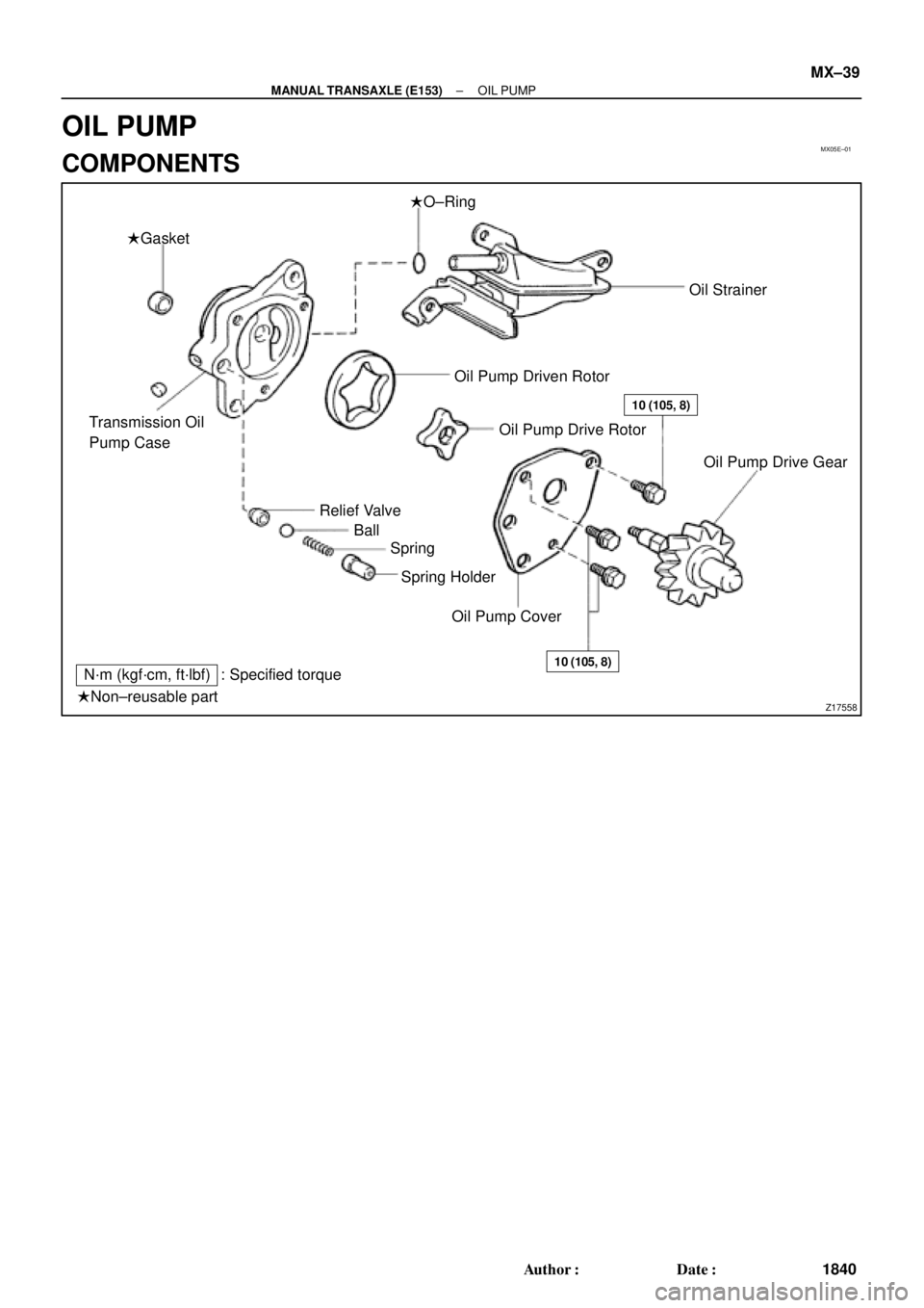
�Gasket�O±Ring
Transmission Oil
Pump Case
Relief Valve
Ball
Spring
Spring Holder
Oil Pump CoverOil Pump Drive Gear Oil Strainer
Oil Pump Driven Rotor
Oil Pump Drive Rotor
10 (105, 8)
10 (105, 8)N´m (kgf´cm, ft´lbf) : Specified torque
�Non±reusable part
± MANUAL TRANSAXLE (E153)OIL PUMP
MX±39
1840 Author�: Date�:
OIL PUMP
COMPONENTS
Page 3842 of 4770
MX05F±01
Z00242
Z00243
Z00244
MX±40
± MANUAL TRANSAXLE (E153)OIL PUMP
1841 Author�: Date�:
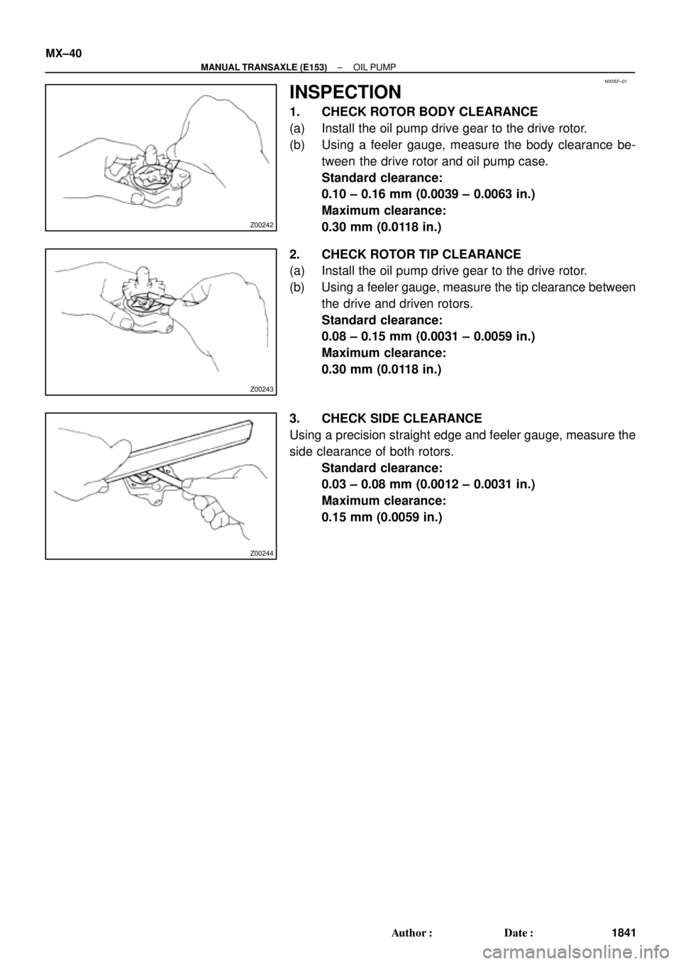
INSPECTION
1. CHECK ROTOR BODY CLEARANCE
(a) Install the oil pump drive gear to the drive rotor.
(b) Using a feeler gauge, measure the body clearance be-
tween the drive rotor and oil pump case.
Standard clearance:
0.10 ± 0.16 mm (0.0039 ± 0.0063 in.)
Maximum clearance:
0.30 mm (0.0118 in.)
2. CHECK ROTOR TIP CLEARANCE
(a) Install the oil pump drive gear to the drive rotor.
(b) Using a feeler gauge, measure the tip clearance between
the drive and driven rotors.
Standard clearance:
0.08 ± 0.15 mm (0.0031 ± 0.0059 in.)
Maximum clearance:
0.30 mm (0.0118 in.)
3. CHECK SIDE CLEARANCE
Using a precision straight edge and feeler gauge, measure the
side clearance of both rotors.
Standard clearance:
0.03 ± 0.08 mm (0.0012 ± 0.0031 in.)
Maximum clearance:
0.15 mm (0.0059 in.)