Page 3793 of 4770
MT0792
SM0201
SST
Z00431
SM0202
SST MX±34
± MANUAL TRANSAXLE (S51)OUTPUT SHAFT
1884 Author�: Date�:
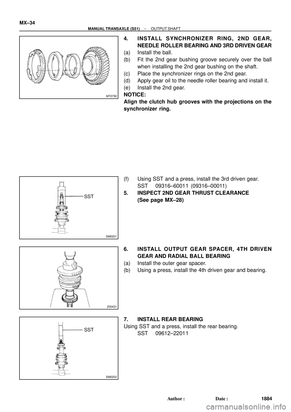
4. INSTALL SYNCHRONIZER RING, 2ND GEAR,
NEEDLE ROLLER BEARING AND 3RD DRIVEN GEAR
(a) Install the ball.
(b) Fit the 2nd gear bushing groove securely over the ball
when installing the 2nd gear bushing on the shaft.
(c) Place the synchronizer rings on the 2nd gear.
(d) Apply gear oil to the needle roller bearing and install it.
(e) Install the 2nd gear.
NOTICE:
Align the clutch hub grooves with the projections on the
synchronizer ring.
(f) Using SST and a press, install the 3rd driven gear.
SST 09316±60011 (09316±00011)
5. INSPECT 2ND GEAR THRUST CLEARANCE
(See page MX±28)
6. INSTALL OUTPUT GEAR SPACER, 4TH DRIVEN
GEAR AND RADIAL BALL BEARING
(a) Install the outer gear spacer.
(b) Using a press, install the 4th driven gear and bearing.
7. INSTALL REAR BEARING
Using SST and a press, install the rear bearing.
SST 09612±22011
Page 3794 of 4770
MX04R±01
Q10277
Shift and Select Lever Shaft
Select Spring Seat
Shift Interlock Plate
Compression Spring
Select Spring Seat No.2Shift Inner Lever No.2Shift Inner Lever No.1Slotted Spring Pin
Control Shaft CoverControl Shaft Lever Lever Lock PinWasher Dust Boot
O±RingOil Seal
�
N´m (kgf´cm, ft´lbf)
: Specified torque
MP Grease Non±reusable partE±Ring
E±Ring
� Compression Spring
6.4 (85, 56 in.´lbf)
�
± MANUAL TRANSAXLE (S51)SHIFT AND SELECT LEVER SHAFT
MX±35
1885 Author�: Date�:
SHIFT AND SELECT LEVER SHAFT
COMPONENTS
Page 3797 of 4770
DIFFERENTIAL CASE
1888 Author�: Date�:
6. Transaxle Case Side:
IF NECESSARY, REPLACE DIFFERENTIAL SIDE
BEARING RETAIN")
Q08145
SST
SM0286
SST
SM0155
SST
Z00442
MT0634
SST MX±38
± MANUAL TRANSAXLE (S51)DIFFERENTIAL CASE
1888 Author�: Date�:
6. Transaxle Case Side:
IF NECESSARY, REPLACE DIFFERENTIAL SIDE
BEARING RETAINER OIL SEAL
(a) Using SST and a hammer, drive out the oil seal from the
retainer.
SST 09950±60020 (09951±00680), 09950±70010
(09951±07150)
(b) Using SST and a hammer, drive in a new oil seal until its
surface is flush with the case surface.
SST 09350±32014 (09351±32130, 09351±32150)
(c) Coat the lip of the oil seal with MP grease.
7. Transmission Case Side:
IF NECESSARY, REPLACE SIDE OIL SEAL
(a) Using a screwdriver and hammer, drive out the oil seal.
(b) Using SST and a hammer, drive in a new oil seal until its
surface is flush with the case surface.
SST 09350±32014 (09351±32130, 09351±32150)
(c) Coat the lip of the oil seal with MP grease.
8. Transaxle Case Side:
IF NECESSARY, REPLACE SIDE BEARING OUTER
RACE
(a) Using a brass bar and hammer, drive out the bearing out-
er race.
(b) Install the bearing retainer without an O±ring.
(c) Install and torque the 6 bolts.
Torque: 18 N´m (185 kgf´cm, 13 ft´lbf)
(d) Place the thinnest shim into the case.
(e) Using SST and a press, install a new bearing outer race.
SST 09950±60020 (09951±00680), 09950±70010
(09951±07150)
(f) Remove the 6 bolts.
(g) Remove the bearing retainer and shim.
Page 3799 of 4770
DIFFERENTIAL CASE
1890 Author�: Date�:
REASSEMBLY
1. ASSEMBLE DIFFERENTIAL CASE
(a) Install the correct thrust washers and side gears. Refer to")
MX04U±01
AT2981
Q08147
MX±40
± MANUAL TRANSAXLE (S51)DIFFERENTIAL CASE
1890 Author�: Date�:
REASSEMBLY
1. ASSEMBLE DIFFERENTIAL CASE
(a) Install the correct thrust washers and side gears. Refer to
the table below, select thrust washers which will ensure
that the backlash is within the specification. Try to select
washers of the same size for both sides.
Standard backlash:
0.05 ± 0.20 mm (0.0020 ± 0.0079 in.)
Thickness mm (in.)Thickness mm (in.)
0.95 (0.0374)1.10 (0.0433)
1.00 (0.0394)1.15 (0.0453)
1.05 (0.0413)1.20 (0.0472)
Install the thrust washers and side gears in the differential
case.
(b) Install the pinion shaft.
(c) Inspect the side gear backlash.
Using a dial indicator, measure the side gear backlash
while holding one pinion gear toward the case.
Standard backlash:
0.05 ± 0.20 mm (0.0020 ± 0.0079 in.)
If the backlash is not within the specification, install a thrust
washer of different thickness.
(d) Using a pin punch and hammer, drive in the straight pin
through the case and hole in the pinion shaft.
(e) Stake the differential case.
2. INSTALL RING GEAR ON DIFFERENTIAL CASE
(a) Clean the contact surface of the differential case and the
threads of the ring gear and differential case.
(b) Heat the ring gear in boiling water.
(c) Carefully take the ring gear out of the water.
(d) After moisture on the ring gear has completely evapo-
rated, quickly install the ring gear to the differential case.
HINT:
Align the matchmarks on the differential case and the ring gear.
(e) Temporarily install the 8 bolts.
NOTICE:
The ring gear set bolts should not be torqued until the ring
gear has cooled sufficiently.
(f) After the ring gear has cooled sufficiently, torque the ring
gear set bolts.
Torque: 83 N´m (850 kgf´cm, 61 ft´lbf)
Page 3804 of 4770
TROUBLESHOOTING
1803 Author�: Date�:
TROUBLESHOOTING
PROBLEM SYMPTOMS TABLE
Use the table below to help you find the cause of the problem. The numbers indicat")
MX04Y±01
MX±2
± MANUAL TRANSAXLE (E153)TROUBLESHOOTING
1803 Author�: Date�:
TROUBLESHOOTING
PROBLEM SYMPTOMS TABLE
Use the table below to help you find the cause of the problem. The numbers indicate the priority of the likely
cause of the problem. Check each part in order. If necessary, replace parts.
SymptomSuspect AreaSee page
1. Oil (Level low)MX±4
Ni
1. Oil (Level low)
2. Oil (Wrong)
MX±4
MX±4Noise2. Oil (Wrong)
3. Gear (Worn or damaged)
MX±4
MX±103. Gear (Worn or damaged)
4. Bearing (Worn or damaged)
MX 10
MX±10
1. Oil (Level too high)MX±4
Oil l k
1. Oil (Level too high)
2. Gasket (Damaged)
MX±4
MX±10Oil leakage2. Gasket (Damaged)
3. Oil seal (Worn or damaged)
MX±10
MX±103. Oil seal (Worn or damaged)
4. O±Ring (Worn or damaged)
MX 10
MX±10
1. Control cable (Faulty)
2. Synchronizer ring (Worn or damaged)MX±49
MX±10
Hard to shift or will not shift
yg( g)
3 Shift key s
pring (Damaged)
MX±24
MX±31
MX±103. Shift key spring (Damaged)MX±10
MX±24
MX±31
1. Locking ball spring (Damaged)MX±10
Jtf
1. Locking ball spring (Damaged)
2. Shift fork (Worn)
MX±10
MX±10Jumps out of gear2. Shift fork (Worn)
3. Gear (Worn or damaged)
MX±10
MX±103. Gear (Worn or damaged)
4. Bearing (Worn or damaged)
MX 10
MX±10
Page 3807 of 4770
MANUAL TRANSAXLE UNIT
MX±5
1806 Author�: Date�:
10. REMOVE 5 TRANSAXLE UPPER SIDE MOUNTING
BOLTS
Torque:
17 m")
Q09986
Q09987
Filler Plug
Oil Level
0 ± 5 mm
Drain Plug
Q09988
± MANUAL TRANSAXLE (E153)MANUAL TRANSAXLE UNIT
MX±5
1806 Author�: Date�:
10. REMOVE 5 TRANSAXLE UPPER SIDE MOUNTING
BOLTS
Torque:
17 mm head: 64 N´m (650 kgf´cm, 47 ft´lbf)
11. REMOVE FRONT WHEEL
Torque: 103 N´m (1,050 kgf´cm, 76 ft´lbf)
12. RAISE VEHICLE
NOTICE:
Make sure that the vehicle is securely supported.
13. REMOVE ENGINE REAR SIDE SHUTTER PLATE AND
LH AND RH FENDER APRON SEALS
14. DRAIN TRANSAXLE OIL
Oil grade: API GL±4 or GL±5
Viscosity: SAE 75W±90
Capacity: 4.2 liters (4.4 US qts, 3.7 Imp. qts)
Torque: 49 N´m (500 kgf´cm, 36 ft´lbf)
15. REMOVE LH AND RH DRIVE SHAFTS
(See page SA±25)
16. REMOVE FRONT EXHAUST PIPE
(a) Remove the 2 bolts and exhaust pipe support stay.
Torque: 33 N´m (330 kgf´cm, 24 ft´lbf)
(b) Remove the 4 nuts and 2 gaskets from the exhaust man-
ifold.
Torque: 62 N´m (630 kgf´cm, 46 ft´lbf)
(c) Remove the 2 bolts, nuts and gasket.
Torque: 56 N´m (570 kgf´cm, 41 ft´lbf)
(d) Remove the 2 set bolts of the No.1 exhaust pipe support
bracket.
Torque: 33 N´m (330 kgf´cm, 24 ft´lbf)
(e) Remove the front exhaust pipe.
Page 3812 of 4770
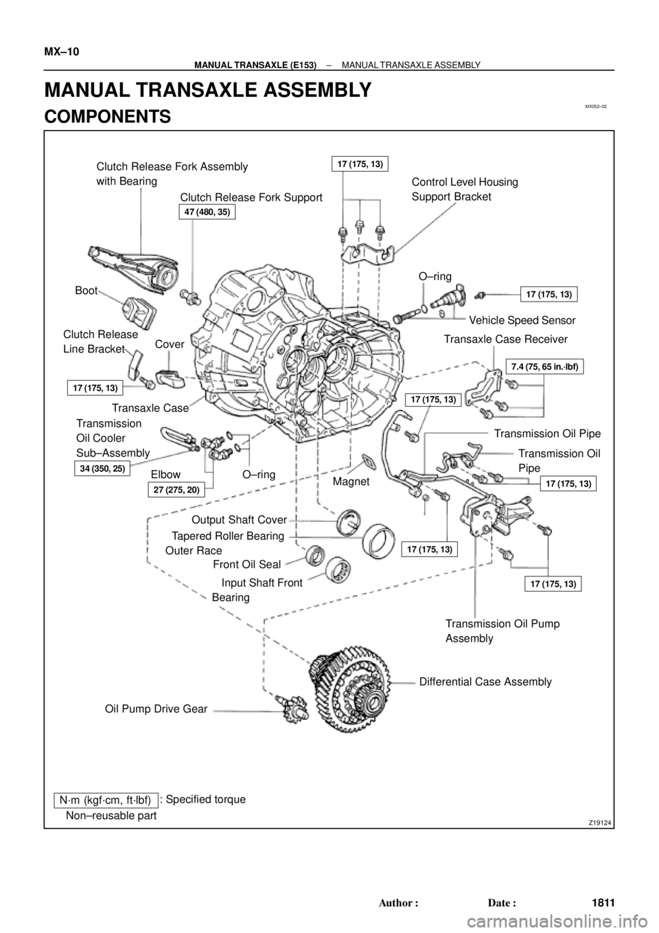
MX052±02
Z19124
Clutch Release Fork Assembly
with Bearing
Clutch Release Fork SupportControl Level Housing
Support Bracket
Boot�O±ring
Vehicle Speed Sensor
Transaxle Case Receiver Clutch Release
Line BracketCover
Transaxle Case
Transmission Oil
Pipe Transmission
Oil Cooler
Sub±Assembly
Elbow�O±ring
Magnet
�
Transmission Oil Pump
Assembly
Differential Case Assembly
Oil Pump Drive Gear�Output Shaft Cover
�Tapered Roller Bearing
Outer Race
�Front Oil Seal
�Input Shaft Front
Bearing
N´m (kgf´cm, ft´lbf): Specified torque
�Non±reusable part
47 (480, 35)
17 (175, 13)
17 (175, 13)
17 (175, 13)
17 (175, 13)
17 (175, 13)
7.4 (75, 65 in.´lbf)
17 (175, 13)
27 (275, 20)
34 (350, 25)
17 (175, 13)
Transmission Oil Pipe MX±10
± MANUAL TRANSAXLE (E153)MANUAL TRANSAXLE ASSEMBLY
1811 Author�: Date�:
MANUAL TRANSAXLE ASSEMBLY
COMPONENTS
Page 3813 of 4770

25 (250, 18)
25 (250, 18)�
In")
Q10278
Reverse Shift Arm Bracket Assembly
Snap Ring
Reverse Shift Fork
No.1 Shift Fork
Straight Screw Plug
Seat
Spring
Ball
No.1 Shift Fork Shaft
Snap Ring
�
24 (240, 17)
25 (250, 18)
25 (250, 18)�
Interlock Roller
No.2 Shift Fork Shaft
Snap Ring
Shift Head25 (250, 18)�
No.3 Shift Fork Shaft
Snap Ring
No.3 Shift Fork
24 (240, 17)
24 (240, 17)
No.2 Shift Fork
Back±Up Light Switch
40 (410, 30)
Straight Screw Plug
13 (130, 9)Slotted Spring
Pin
Reverse Restrict
Pin
No.2 Oil Receiver PipeShift and Select Lever
Shaft Lock Bolt
Breather Plug
49 (500, 36)
20 (200, 14)
29 (300, 22)
�
�
�
�
20 (200, 14)x 17
Shift and Select Lever
Shaft Assembly
No.2 Selecting Bellcrank with
Selecting Bellcrank Support
29 (300, 22)
x 10
Transmission Case Cover �
Drain Plug49 (500, 36)
Transmission Case Filler Plug
49 (500, 36)
No.1 Oil Receiver Pipe
17 (175, 13)
N´m (kgf´cm, ft´lbf) : Specified torque
�Non±reusable part
�Precoated partGasket �Gasket
�Gasket
�Gasket
�Gasket�
�
49 (500, 36)
�Gasket
17 (175, 13)
± MANUAL TRANSAXLE (E153)MANUAL TRANSAXLE ASSEMBLY
MX±11
1812 Author�: Date�: