Page 2975 of 4770
BR3795
OK NG OK NG
OK NGOK NG
R00948
± DIAGNOSTICSANTI±LOCK BRAKE SYSTEM (BOSCH Made)
DI±555
790 Author�: Date�:
2 Check for open and short circuit in harness and connector between each speed
sensor and ECU (See page IN±31).
NG Repair or replace harness or connector.
OK
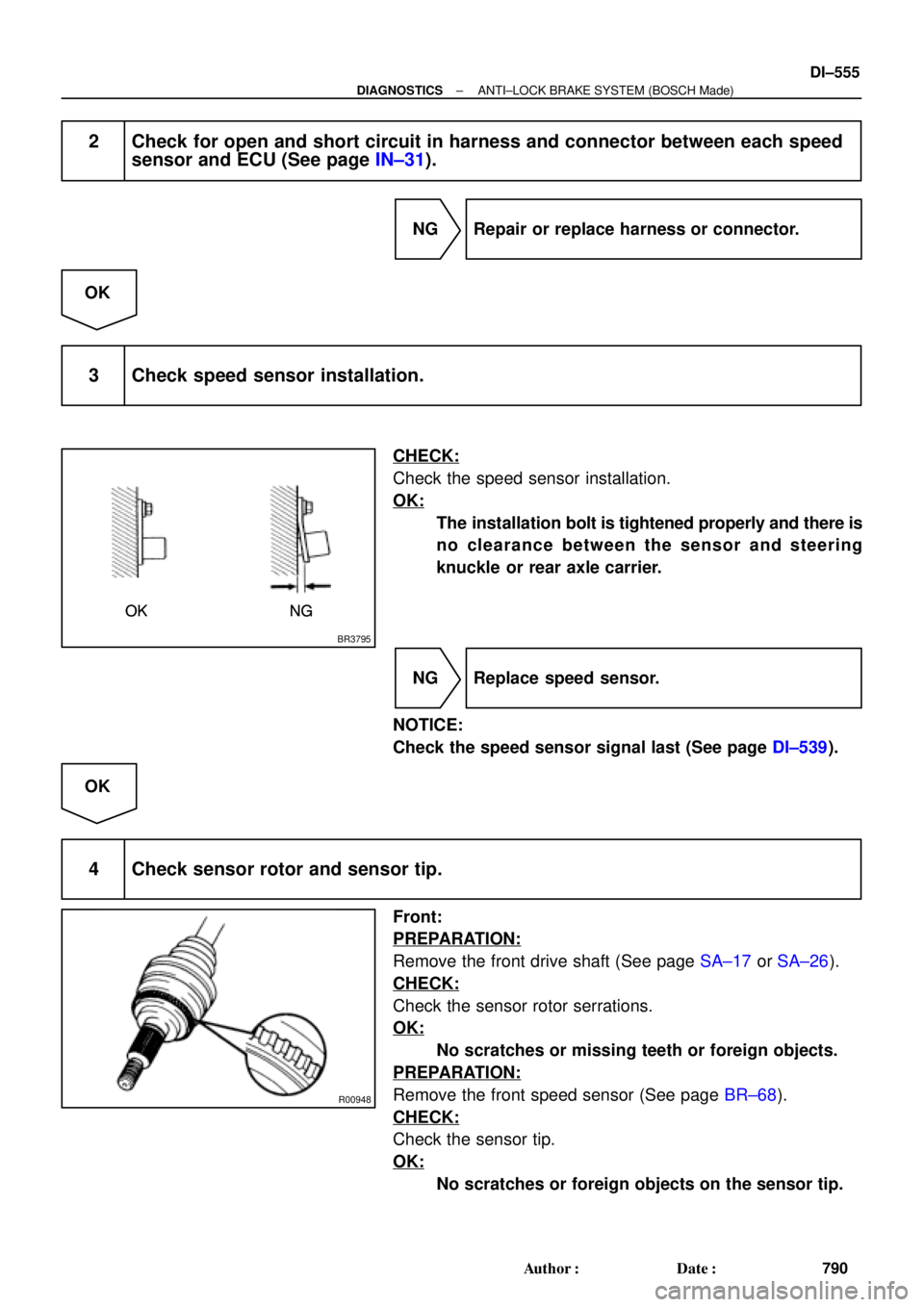
3 Check speed sensor installation.
CHECK:
Check the speed sensor installation.
OK:
The installation bolt is tightened properly and there is
no clearance between the sensor and steering
knuckle or rear axle carrier.
NG Replace speed sensor.
NOTICE:
Check the speed sensor signal last (See page DI±539).
OK
4 Check sensor rotor and sensor tip.
Front:
PREPARATION:
Remove the front drive shaft (See page SA±17 or SA±26).
CHECK:
Check the sensor rotor serrations.
OK:
No scratches or missing teeth or foreign objects.
PREPARATION:
Remove the front speed sensor (See page BR±68).
CHECK:
Check the sensor tip.
OK:
No scratches or foreign objects on the sensor tip.
Page 2976 of 4770
R00947
DI±556
± DIAGNOSTICSANTI±LOCK BRAKE SYSTEM (BOSCH Made)
791 Author�: Date�:
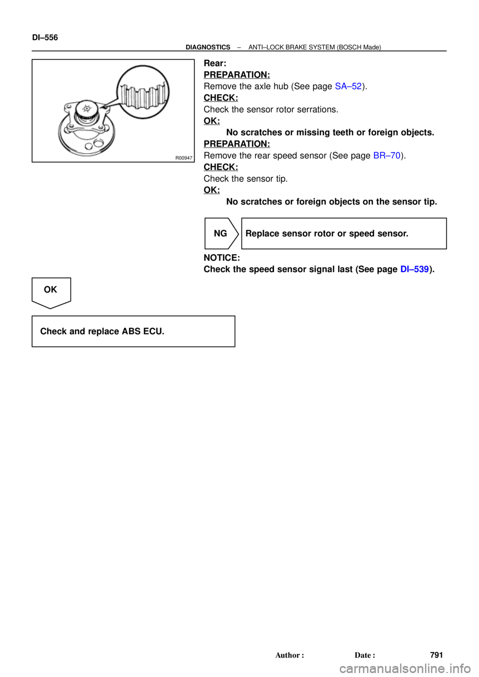
Rear:
PREPARATION:
Remove the axle hub (See page SA±52).
CHECK:
Check the sensor rotor serrations.
OK:
No scratches or missing teeth or foreign objects.
PREPARATION:
Remove the rear speed sensor (See page BR±70).
CHECK:
Check the sensor tip.
OK:
No scratches or foreign objects on the sensor tip.
NG Replace sensor rotor or speed sensor.
NOTICE:
Check the speed sensor signal last (See page DI±539).
OK
Check and replace ABS ECU.
Page 2977 of 4770

DI±557
792 Author�: Date�:
DTC 37 Speed Sensor Rotor Faulty
CIRCUIT DESCRIPTION
DTC No.DTC Detecting ConditionTrouble Area
37
Detection of any of co")
± DIAGNOSTICSANTI±LOCK BRAKE SYSTEM (BOSCH Made)
DI±557
792 Author�: Date�:
DTC 37 Speed Sensor Rotor Faulty
CIRCUIT DESCRIPTION
DTC No.DTC Detecting ConditionTrouble Area
37
Detection of any of conditions from 1. through 3.:
1. Occurrence of differential to some degree in the wheel
speed between the front and rear wheels of either left or
right side of the vehicle and the front left and right
wheels. (Detection of differential in mini tire size, spin-
ning wheel and decelerating wheel.)
2. Continuous ABS control for 60 sec. or more.
3. Interference on 1 or more wheels for 20 sec. with the
brake pedal depressed, or for 5 sec. when the brake
pedal is not depressed.
�Speed sensor
�Sensor rotor
�ECU
INSPECTION PROCEDURE
1 Check sensor rotor (See page DI±552).
NG Replace sensor rotor.
OK
2 Check speed sensor (See page DI±552).
NG Replace speed sensor.
OK
3 Check for open and short circuit in harness and connector between speed sen-
sor and ECU (See page IN±31).
NG Repair or replace harness and connector.
OK
Check and replace ABS ECU.
DI044±04
Page 2981 of 4770
F00125
MAIN
Battery ALT F4B±R
F91B
1C
STOP
B±G4
1 Instrument Panel J/B
FL Block
1 7 WA6
21S 5IK3 J28
G±WECU
J27
1RSTP
Stop Light SwitchJ/C
7
G±R
H10Light Failure
Sensor R
W±B A
R9 R11 C14
BP BL 11R
2
4
G±W G±W G±WG±W 1
Instrument
Panel J/B
2 1
G±RG±R
W±B W±B
W±B H10R9
R11
J/C
A A High
Mounted
Stop
LightRight
Stop
LightLeft
Stop
Light
J405 2
12
2
5
W±B
W±B
± DIAGNOSTICSANTI±LOCK BRAKE SYSTEM (BOSCH Made)
DI±561
796 Author�: Date�:
DTC 58 Stop Light Switch Circuit
CIRCUIT DESCRIPTION
DTC No.DTC Detecting ConditionTrouble Area
49
Stop light switch circuit is open, and stop light switch
voltage is in the level between 65 % or more and less
than 93 % of the battery voltage.�Stop light switch
�Stop light switch circuit
�ECU
WIRING DIAGRAM
INSPECTION PROCEDURE
1 Check operation of stop light.
CHECK:
Check that stop light lights up when brake pedal is depressed and turns off when brake pedal is released.
NG Repair stop light circuit (See page BE±36).
OK
DI046±09
Page 2989 of 4770
F00095
11ECU
R±Y
AA6 IK2
3
J/CDLC1
BR
Ts
J22: (1MZ±FE)16
EC5
E
1Ts
BRAII38
J23: (5S±FE)R±Y
11ECU
R±Y
AA6 IK2
3
J/CDLC1
BR
Ts
J22: (1MZ±FE)165
E
1Ts
BRAII38
J23: (5S±FE)R±Y B±Y (1MZ±FE)
LG (5S±FE)
AB0119S08096
F00446DLC1 DLC1
DLC1
DLC1
DLC1
Ts
DLC1 E1
ON
± DIAGNOSTICSANTI±LOCK BRAKE SYSTEM (BOSCH Made)
DI±569
804 Author�: Date�:
Ts Terminal Circuit
CIRCUIT DESCRIPTION
The sensor check circuit detects abnormalities in the speed sensor signal which cannot be detected with
the DTC check.
Connecting terminals Ts and E
1 of the DLC1 in the engine compartment starts the check.
WIRING DIAGRAM
INSPECTION PROCEDURE
1 Check voltage between terminals Ts and E1 of DLC1.
CHECK:
(a) Turn the ignition switch ON.
(b) Measure voltage between terminals Ts and E
1 of DLC1.
OK:
Voltage: 10 ± 14 V
OK If ABS warning light does not blink even after Ts
and E
1 are connected, the ECU may be defec-
tive.
NG
DI04A±08
Page 2992 of 4770
DI04C±02
Check and Clear DTC (Precheck)
P.
DI±574
Items inside
are titles of pages in this manual,
with the page number in the bottom portion. See
the pages for detailed explanations.
Symptom Simulation
P. IN±21
Symptom
does not occur
Symptom
occurs
DTC Check
P. DI±574
Sensor CheckCircuit Inspection
DTC Chart
P. DI±578 Malfunction codeProblem Symptoms Table
P. DI±583
Check for Fluid Leakage
P.DI±623
Identification of Problem
Normal code
Repair
Confirmation Test
End
1
2
3
4
5
67
89
10
11
Step 2, 5, 8, 9, 11:Diagnostic steps permitting the use of the
TOYOTA hand±held tester or TOYOTA
break±out±box.
Vehicle Brought to Workshop
Customer Problem Analysis
P. DI±573
Problem Symptom Confirmation
P.DI±584 ~ DI±620 DI±572
± DIAGNOSTICSABS & TRACTION CONTROL SYSTEM
807 Author�: Date�:
ABS & TRACTION CONTROL SYSTEM
HOW TO PROCEED WITH TROUBLESHOOTING
Troubleshoot in accordance with the procedure on the following pages.
Page 2996 of 4770

72 67
ON
OFF
0.5 sec. 0.5 sec. 0.5 sec. 0.5 sec.1.5 sec.
2.5 sec.4 sec.
Repeat DI±576
± DIAGNOSTI")
F02201
DLC1
TsTc E
1
BR3904
0.13 sec. 0.13 sec.
ON
OFF
BR3893
Malfunction Code (Example Code 72, 76)
72 67
ON
OFF
0.5 sec. 0.5 sec. 0.5 sec. 0.5 sec.1.5 sec.
2.5 sec.4 sec.
Repeat DI±576
± DIAGNOSTICSABS & TRACTION CONTROL SYSTEM
811 Author�: Date�:
2. SPEED SENSOR SIGNAL
(a) Check the speed sensor signal.
(1) Turn the ignition switch OFF.
(2) Using SST, connect terminals Ts and E
1 of DLC1.
SST 09843 ± 18020
(3) Start the engine.
(4) Check that the ABS warning light blinks.
HINT:
If the ABS warning light does not blink, inspect the ABS warning
light circuit (See page DI±612).
(5) Drive vehicle straight forward.
HINT:
Drive vehicle faster than 45 km/h (28 mph) for several seconds.
(6) Stop the vehicle.
(7) Using SST, connect terminals Tc and E
1 of DLC1.
SST 09843 ± 18020
(8) Read the number of blinks of the ABS warning light.
HINT:
�See the list of DTC shown on the next page.
�If 2 or more malfunctions are indicated at the same time,
the lowest numbered code will be displayed 1st.
�If every sensor is normal, a normal code is output (A cycle
of 0.25 sec. ON and 0.25 sec. OFF is repeated).
(9) After doing the check, disconnect the SST from ter-
minals Ts and E
1, Tc and E1 of DLC1, and turn igni-
tion switch OFF.
SST 09843 ± 18020
Page 2997 of 4770
 Using TOYOTA hand±held tester, check the DTC.
(1) Do step 1. ~ 6. on the previous page")
H07517
TOYOTA
Hand±held Tester
DLC2
± DIAGNOSTICSABS & TRACTION CONTROL SYSTEM
DI±577
812 Author�: Date�:
(b) Using TOYOTA hand±held tester, check the DTC.
(1) Do step 1. ~ 6. on the previous page.
(2) Hook up the TOYOTA hand±held tester to the
DLC2.
(3) Read the DTC by following the prompts on the tes-
ter screen.
Please refer to the TOYOTA hand±held tester oper-
ator 's manual for further details.
DTC of speed sensor check function:
Code No.DiagnosisTrouble Area
71Low output voltage of right front speed sensor
�Right front speed sensor
�Sensor installation
�Right front speed sensor rotor
72Low output voltage of left front speed sensor
�Left front speed sensor
�Sensor installation
�Left front speed sensor rotor
73Low output voltage of right rear speed sensor
�Right rear speed sensor
�Sensor installation
�Right rear speed sensor rotor
74Low output voltage of left rear speed sensor
�Left rear speed sensor
�Sensor installation
�Left rear speed sensor rotor
75Abnormal change in output voltage of right front speed
sensor�Right front speed sensor rotor
76Abnormal change in output voltage of left front speed
sensor�Left front speed sensor rotor
77Abnormal change in output voltage of right rear speed
sensor�Right rear speed sensor rotor
78Abnormal change in output voltage of left rear speed sensor�Left rear speed sensor rotor

16
EC5
E
1Ts
BRAII38
J23: (5S±FE)R±Y
11ECU
R±Y
AA6 IK2
3
J/CDLC1
BR
Ts
J22: (1MZ±FE)165
E
1Ts
BRAII38
J23: (5S±FE)R±Y B±Y (1MZ±FE)
LG (5")

P.
DI±574
Items inside
are titles of pages in this manual,
with the page number in the bottom portion. See
the pages for detailed explanations.
Symptom Simu")