Page 2869 of 4770

DI±449
684 Author�: Date�:
DIAGNOSTIC TROUBLE CODE CHART
If a DTC is displayed during the DTC check, check the circuit listed for that code in the")
DI02F±02
± DIAGNOSTICSAUTOMATIC TRANSAXLE (A541E)
DI±449
684 Author�: Date�:
DIAGNOSTIC TROUBLE CODE CHART
If a DTC is displayed during the DTC check, check the circuit listed for that code in the table below and pro-
ceed to the page given.
* : ±...MIL does not light /�...MIL light up
DTC No.
(See Page)Detection ItemTrouble AreaMIL *Memory
P0500
(DI±456)Vehicle Speed Sensor Malfunc-
tion
(No.1 Vehicle Speed Sensor)
�Open or short in No.1 vehicle speed sensor circuit
�No.1 vehicle speed sensor
�Combination meter
�ECM
�Automatic transaxle (clutch, brake or gear etc.)
��
P0750
(DI±460)Shift Solenoid A Malfunction
(Shift Solenoid Valve No.1)�Shift solenoid valve No.1 is stuck open or closed
�Valve body is blocked up or stuck
�Automatic transaxle (clutch, brake or gear etc.)
��
P0753
(DI±462)Shift Solenoid A Electrical Mal-
function
(Shift Solenoid Valve No.1)�Open or short in shift solenoid valve No.1 circuit
�Shift solenoid valve No.1
�ECM
��
P0755
(DI±460)Shift Solenoid B Malfunction
(Shift Solenoid Valve No.2)�Shift solenoid valve No.2 is stuck open or closed
�Valve body is blocked up or stuck
�Automatic transaxle (clutch, brake or gear etc.)
��
P0758
(DI±462)Shift Solenoid B Electrical Mal-
function
(Shift Solenoid Valve No.2)�Open or short in shift solenoid valve No.2 circuit
�Shift solenoid valve No.2
�ECM
��
P0770
(DI±466)Shift Solenoid E Malfunction
(Shift Solenoid Valve SL)
�Shift solenoid valve SL is stuck open or closed
�Valve body is blocked up or stuck
�Lock±up clutch
�Automatic transaxle (clutch, brake or gear etc.)
��
P0773
(DI±468)Shift Solenoid E Electrical Mal-
function
(Shift Solenoid Valve SL)�Open or short in shift solenoid valve SL circuit
�Shift solenoid valve SL
�ECM
��
P1520
(DI±472)Stop Light Switch Signal Mal-
function�Open or short in stop light switch circuit
�Stop light switch
�ECM
��
P1705
(DI±473)NC2 Revolution Sensor Circuit
Malfunction
(Direct Clutch Speed Sensor)�Open or short in direct clutch speed sensor circuit
�Direct clutch speed sensor
�ECM
��
P1765
(DI±476)
Linear Solenoid for Accumulator
Pressure Control Circuit Mal-
function
(Shift Solenoid Valve SLN)�Open or short in shift solenoid valve SLN circuit
�Shift solenoid valve SLN
�ECM
��
P1780
(DI±479)Park/Neutral Position Switch
Malfunction�Short in park/neutral position switch circuit
�Park/neutral position switch
�ECM
��
Page 2870 of 4770
DI02G±02
Q07932
Engine Coolant Temp. SensorCruise Control ECUThrottle Position Sensor
O/D Main Switch
O/D OFF Indicator LIght
DLC3
DLC2
Stop Light Switch
Vehicle Speed Sensor
Shift Solenoid Valve SLN
Shift Solenoid Valve No.1, No2 Shift Solenoid Valve SL
Park/Neutral Position Switch Direct Clutch Speed SensorECM
Crankshaft Position
Sensor
DI±450
± DIAGNOSTICSAUTOMATIC TRANSAXLE (A541E)
685 Author�: Date�:
PARTS LOCATION
Page 2876 of 4770

691 Author�: Date�:
CIRCUIT")
DI1KB±01
A00223
Vehicle Speed
Sensor4±Pulse
Combination
Meter
ECM
Transaxle
Vehicle Speed Sensor
4±Pulse
Q00515 Q00514
DI±456
± DIAGNOSTICSAUTOMATIC TRANSAXLE (A541E)
691 Author�: Date�:
CIRCUIT INSPECTION
DTC P0500 Vehicle Speed Sensor Malfunction
CIRCUIT DESCRIPTION
The vehicle speed sensor outputs a 4±pulse signal for every revolution of the rotor shaft, which is rotated
by the transmission output shaft via the driven gear. After this signal is converted into a more precise rectan-
gular waveform by the waveform shaping circuit inside the combination meter, it is then transmitted to the
ECM. The ECM determines the vehicle speed based on the frequency of these pulse signals.
DTC No.DTC Detecting ConditionTrouble Area
P0500
No vehicle speed sensor signal to ECM under conditions (a)
and (b)
(2 trip detection logic)
(a) Park/neutral position switch is OFF
(b) Vehicle is being driven�Open or short in vehicle speed sensor circuit
�Vehicle speed sensor
�Combination meter
�ECM
At ti t l (lthb k t )Clutch or brake slips or gear is broken�Automatic transaxle (clutch, brake or gear etc.)
WIRING DIAGRAM
See page DI±333.
Page 2877 of 4770
P23875
A02373A02155
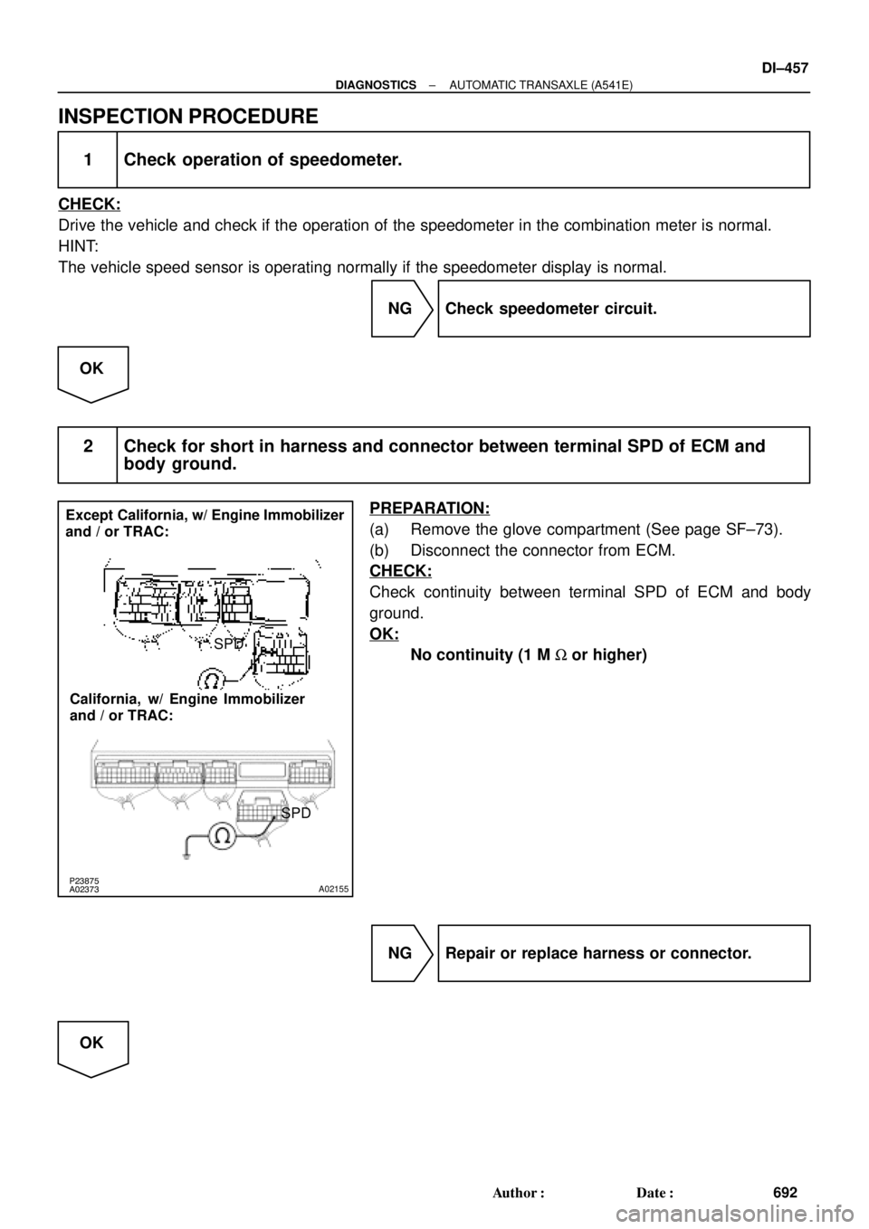
Except California, w/ Engine Immobilizer
and / or TRAC:
California, w/ Engine Immobilizer
and / or TRAC:SPD
SPD
± DIAGNOSTICSAUTOMATIC TRANSAXLE (A541E)
DI±457
692 Author�: Date�:
INSPECTION PROCEDURE
1 Check operation of speedometer.
CHECK:
Drive the vehicle and check if the operation of the speedometer in the combination meter is normal.
HINT:
The vehicle speed sensor is operating normally if the speedometer display is normal.
NG Check speedometer circuit.
OK
2 Check for short in harness and connector between terminal SPD of ECM and
body ground.
PREPARATION:
(a) Remove the glove compartment (See page SF±73).
(b) Disconnect the connector from ECM.
CHECK:
Check continuity between terminal SPD of ECM and body
ground.
OK:
No continuity (1 M W or higher)
NG Repair or replace harness or connector.
OK
Page 2880 of 4770

695 Author�: Date�:
DTC P0750, P0755 Shift Solenoid A/B Malfunction
(Shift Solenoid Valve No.1/No.2)
SYSTEM DESCRIPTION
The ECM uses signals fr")
Q07781
DI±460
± DIAGNOSTICSAUTOMATIC TRANSAXLE (A541E)
695 Author�: Date�:
DTC P0750, P0755 Shift Solenoid A/B Malfunction
(Shift Solenoid Valve No.1/No.2)
SYSTEM DESCRIPTION
The ECM uses signals from the vehicle speed sensor and direct clutch speed sensor to detect the actual
gear position (1st, 2nd, 3rd or O/D gear).
Then the ECM compares the actual gear with the shift schedule in the ECM memory to detect mechanical
trouble of the shift solenoid valves, valve body or automatic transaxle (clutch, brake or gear etc.)
DTC No.DTC Detecting ConditionTrouble Area
P0750
P0755During normal driving, the gear required by the ECM does not
match the actual gear
(2 trip detection logic)�Shift solenoid valve No.1/No.2 is stuck open or closed
�Valve body is blocked up or stuck
�Automatic transaxle (clutch, brake or gear etc.)
Check the shift solenoid valve No.1 when DTC P0750 is output and check the shift solenoid valve No.2 when
DTC P0755 is output.
INSPECTION PROCEDURE
1 Check shift solenoid valve No.1 or No.2 operation.
PREPARATION:
(a) Remove the oil pan.
(b) Remove the shift solenoid valve No.1 or No.2.
CHECK:
(a) Applying 490 kPa (5 kgf/cm2, 71 psi) of compressed air,
check that the solenoid valve does not leak air.
(b) When battery positive voltage is supplied to the shift sole-
noid valve, check that the valve opens.
NG Replace the shift solenoid valve No.1 or No.2.
OK
DI02K±02
Page 2886 of 4770

701 Author�: Date�:
DTC P0770 Shift Solenoid E Malfunction
(Shift Solenoid V")
Q04874
Controlled
Pressure Line
Pressure
Drain Controlled
Pressure
Q08040
DI±466
± DIAGNOSTICSAUTOMATIC TRANSAXLE (A541E)
701 Author�: Date�:
DTC P0770 Shift Solenoid E Malfunction
(Shift Solenoid Valve SL)
SYSTEM DESCRIPTION
The ECM uses the signals from the throttle position sensor, air±
flow meter and crankshaft position sensor to monitor the en-
gagement condition of the lock±up clutch.
Then the ECM compares the engagement condition of the
lock±up clutch with the lock±up schedule in the ECM memory
to detect mechanical trouble of the shift solenoid valve SL,
valve body, torque converter clutch or automatic transaxle
(clutch, brake or gear etc.).
DTC No.DTC Detecting ConditionTrouble Area
P0770
�Lock±up does not occur when driving in the lock±up range
(normal driving at 80 km/h [50 mph]), or lock±up remains ON
in the lock±up OFF range.
(2 trip detection logic)
�When lock±up is ON, clutch or brake slips or gear is broken.�Shift solenoid valve SL is stuck open or closed
�Valve body blocked up or stuck
�Lock±up clutch
�Automatic transaxle (clutch, brake or gear etc.)
INSPECTION PROCEDURE
1 Check solenoid valve SL operation.
PREPARATION:
(a) Remove the oil pan.
(b) Remove the shift solenoid valve SL.
CHECK:
(a) Applying 490 kPa (5 kgf/cm2, 71 psi) of compressed air,
check that the solenoid valve does not leak air.
(b) When battery positive voltage is supplied to the shift sole-
noid valve, check that the solenoid valve opens.
NG Replace the solenoid valve SL.
OK
DI02M±02
Page 2893 of 4770

Q04869
NC2 Revolution Sensor
D01094
Direct Clutch
Speed Sensor 2V3
1
V3
G R
E99
E94ECM
NC2
+
NC2±4 ~ 6 V
*1: Except California, w/ Engine Immobilizer and / or TRAC
*2: California, w/ Engine Immobilizer and / or TRAC*2 *1
E1114
26 *2 *1
E11
± DIAGNOSTICSAUTOMATIC TRANSAXLE (A541E)
DI±473
708 Author�: Date�:
DTC P1705 NC2 Revolution Sensor Circuit Malfunction
(Direct Clutch Speed Sensor)
CIRCUIT DESCRIPTION
This sensor detects the rotation speed of the direct clutch drum.
By comparing the direct clutch speed signal and the vehicle
speed sensor signal, the ECM detects the shift timing of the
gears and appropriately controls the engine torque and hydrau-
lic pressure in response to various conditions, thus performing
smooth gear shifting.
DTC No.DTC Detecting ConditionTrouble Area
P1705
The ECM detects conditions (a), (b), (c), (d), (e) and (f) conti-
nuity for 4 sec or more.
(2 trip detection logic)
(a) Vehicle speed : 32 km/h (20 mph) or more
(b) 3rd or 4th gear
(c) NC2 < 300 rpm
(d) Park/neutral position switch: OFF
(e) Solenoid valves and vehicle speed sensor are normal
(f) L position: OFF
�Open or short in direct clutch speed sensor circuit
�Direct clutch speed sensor
�ECM
WIRING DIAGRAM
DI02P±02
Page 2895 of 4770
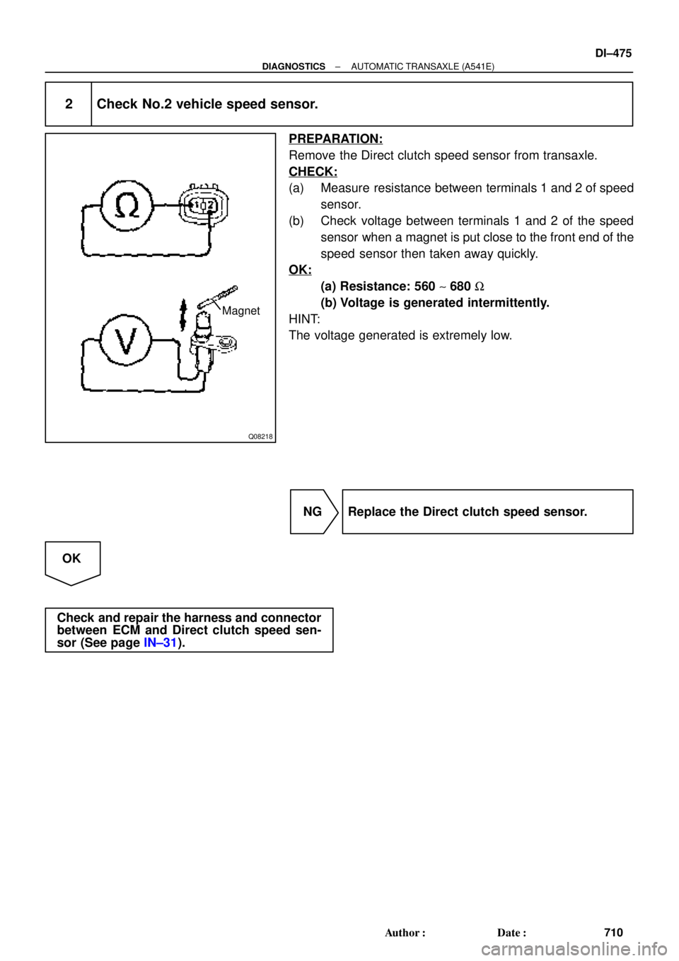
Q08218
Magnet
± DIAGNOSTICSAUTOMATIC TRANSAXLE (A541E)
DI±475
710 Author�: Date�:
2 Check No.2 vehicle speed sensor.
PREPARATION:
Remove the Direct clutch speed sensor from transaxle.
CHECK:
(a) Measure resistance between terminals 1 and 2 of speed
sensor.
(b) Check voltage between terminals 1 and 2 of the speed
sensor when a magnet is put close to the front end of the
speed sensor then taken away quickly.
OK:
(a) Resistance: 560 ~ 680 W
(b) Voltage is generated intermittently.
HINT:
The voltage generated is extremely low.
NG Replace the Direct clutch speed sensor.
OK
Check and repair the harness and connector
between ECM and Direct clutch speed sen-
sor (See page IN±31).