Page 2769 of 4770

HAFR (+)
± DIAGNOSTICSENGINE (1MZ±FE)
DI±349
584 Author�: Date�:
DTC P1135 A/F Sensor Heater Circuit Malfunction
(Bank 1 Sensor 1) (Only for California Spec.)
DTC P1155 A/F Sensor")
A02509
HAFL (+)
HAFR (+)
± DIAGNOSTICSENGINE (1MZ±FE)
DI±349
584 Author�: Date�:
DTC P1135 A/F Sensor Heater Circuit Malfunction
(Bank 1 Sensor 1) (Only for California Spec.)
DTC P1155 A/F Sensor Heater Circuit Malfunction
(Bank 2 Sensor 1) (Only for California Spec.)
CIRCUIT DESCRIPTION
Refer to DTC P0125 (Insufficient Coolant Temp. for Closed Loop Fuel Control (Only for California Spec.))
on page DI±249.
DTC No.DTC Detecting ConditionTrouble Area
P1135
When heater operates, heater current exceeds 8 A
(2 trip detection logic)�Open or in heater circuit of A/F sensors
(bank 1, 2 sensor 1)P1135
P1155Heater current of 0.25 A or less when heater operates
(2 trip detection logic)
(bank 1, 2 sensor 1)
�A/F sensors (bank 1, 2 sensor 1) heater
�ECM
WIRING DIAGRAM
Refer to DTC P0125 (Insufficient Coolant Temp. for Closed Loop Fuel Control (Only for California Spec.))
on page DI±249.
INSPECTION PROCEDURE
HINT:
Read freeze frame data using TOYOTA hand±held tester or OBD II scan tool. Because freeze frame records
the engine conditions when the malfunction is detected, when troubleshooting it is useful for determining
whether the vehicle was running or stopped, the engine warmed up or not, the air±fuel ratio lean or rich, etc.
at the time of the malfunction.
1 Check voltage between terminal HAFR, HAFL of ECM connector and body
ground.
PREPARATION:
(a) Remove glove compartment (See page SF±73).
(b) Turn the ignition switch ON.
CHECK:
Measure voltage between terminals HAFR, HAFL of the ECM
connector and body ground.
OK:
Voltage: 9 ~ 14 V
OK Check and replace ECM (See page IN±31).
NG
DI1K8±04
Page 2770 of 4770
DI±350
± DIAGNOSTICSENGINE (1MZ±FE)
585 Author�: Date�:
2 Check resistance of A/F sensor heaters (bank 1, 2 sensor 1) (See page SF±68).
NG Replace A/F sensors (bank 1, 2 sensor 1).
OK
Check and repair harness or connector between EFI main relay (Marking: EFI) and A/F sensors
(bank 1, 2 sensor 1), and A/F sensors (bank 1, 2 sensor 1) and ECM (See page IN±31).
Page 2771 of 4770

S00251
From BatteryIgnition Coil
Spark Plug
IGC1
IGC2
IGC3
GND TA C IGT1
IGT2
IGT3
IGF
To Tachometer ECM G
NE
Camshaft
Position
Sensor
Crankshaft
Position
Sensor
Various
SensorNo.2 Cylinder
No.1 Cylinder
No.4 Cylinder
No.3 Cylinder
No.6 Cylinder
No.5 Cylinder
± DIAGNOSTICSENGINE (1MZ±FE)
DI±351
586 Author�: Date�:
DTC P1300 Igniter Circuit Malfunction
CIRCUIT DESCRIPTION
A DIS (Direct Ignition System) has been adopted. The DIS improves the ignition timing accuracy, reduces
high±voltage loss, and enhances the overall reliability of the ignition system by eliminating the distributor.
The DIS is a 2±cylinder simultaneous ignition system which ignites 2 cylinders simultaneously with one igni-
tion coil. In the 2±cylinder simultaneous ignition system, each of the 2 spark plugs is connected to the end
of the secondary winding. High voltage generated in the secondary winding is applied directly to the spark
plugs. The sparks of the 2 spark plugs pass simultaneously from the center electrode to the ground elec-
trode.
The ECM determines ignition timing and outputs the ignition signals (IGT) for each cylinder. Based on IGT
signals, the igniter controls the primary ignition signals (IGC) for all ignition coils. At the same time, the igniter
also sends an ignition confirmation signal (IGF) as a fail±safe measure to the ECM.
DTC No.DTC Detecting ConditionTrouble Area
P1300
Condition (a) is repeated 3 times consecutively during 6
consecutively IGT signals while engine is running
(a) IGF signal is not input to ECM for 2 or more ignitions�Open or short in IGF or IGT circuit from igniter to ECM
�Igniter
�ECM
DI084±06
Page 2777 of 4770

DI±357
592 Author�: Date�:
DTC P1335 Crankshaft Position Sensor Circuit
Malfunction (during engine running)
CIRCUIT DESCRIPTION
Refer to DTC P0335 (Crankshaft Position")
± DIAGNOSTICSENGINE (1MZ±FE)
DI±357
592 Author�: Date�:
DTC P1335 Crankshaft Position Sensor Circuit
Malfunction (during engine running)
CIRCUIT DESCRIPTION
Refer to DTC P0335 (Crankshaft Position Sensor ºAº Circuit Malfunction) on page DI±287.
DTC No.DTC Detecting ConditionTrouble Area
P1335No crankshaft position sensor signal to ECM with engine
speed 1,000 rpm or more
�Open or short in crankshaft position sensor circuit
�Crankshaft position sensor
�Starter
�ECM
WIRING DIAGRAM
Refer to DTC P0335 (Crankshaft Position Sensor ºAº Circuit Malfunction) on page DI±287.
INSPECTION PROCEDURE
Read freeze frame data using TOYOTA hand±held tester or OBD II scan tool. Because freeze frame records
the engine conditions when the malfunction is detected, when troubleshooting it is useful for determining
whether the vehicle was running or stopped, the engine warmed up or not, the air±fuel ratio lean or rich, etc.
at the time of the malfunction.
Refer to DTC P0335 (Crankshaft Position Sensor ºAº Circuit Malfunction) on page DI±287.
DI085±06
Page 2778 of 4770
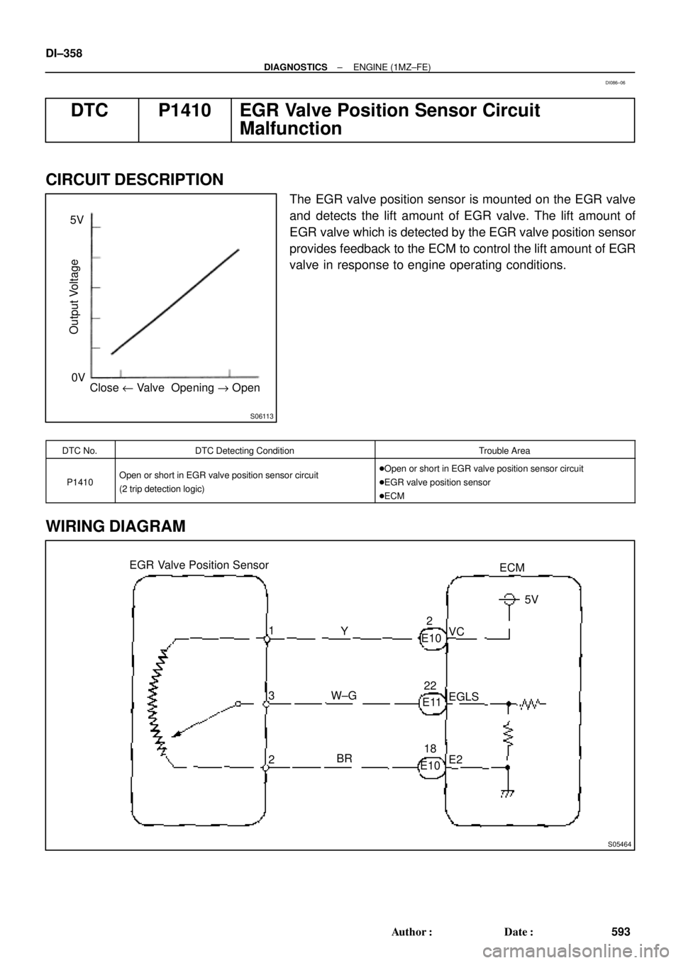
S06113
Close u Valve Opening " Open 0V 5V
Output Voltage
S05464
EGR Valve Position Sensor
3ECM
1
2Y
W±G
BRVC5V
EGLS
E2 E102
E1122
E1018 DI±358
± DIAGNOSTICSENGINE (1MZ±FE)
593 Author�: Date�:
DTC P1410 EGR Valve Position Sensor Circuit
Malfunction
CIRCUIT DESCRIPTION
The EGR valve position sensor is mounted on the EGR valve
and detects the lift amount of EGR valve. The lift amount of
EGR valve which is detected by the EGR valve position sensor
provides feedback to the ECM to control the lift amount of EGR
valve in response to engine operating conditions.
DTC No.DTC Detecting ConditionTrouble Area
P1410Open or short in EGR valve position sensor circuit
(2 trip detection logic)�Open or short in EGR valve position sensor circuit
�EGR valve position sensor
�ECM
WIRING DIAGRAM
DI086±06
Page 2779 of 4770

BE6653S05694
S05742
1
2
± DIAGNOSTICSENGINE (1MZ±FE)
DI±359
594 Author�: Date�:
INSPECTION PROCEDURE
HINT:
�If DTCs ºP0110º (Intake Air Temp. Circuit Malfunction), ºP0115º (Engi")
A00379
ON
1 (+)
BE6653S05694
S05742
1
2
± DIAGNOSTICSENGINE (1MZ±FE)
DI±359
594 Author�: Date�:
INSPECTION PROCEDURE
HINT:
�If DTCs ºP0110º (Intake Air Temp. Circuit Malfunction), ºP0115º (Engine Coolant Temp. Circuit Mal-
function), ºP0120º (Throttle/Pedal Position/Switch ºAº Circuit Malfunction), ºP1410º (EGR Valve Posi-
tion Sensor Circuit Malfunction) are output simultaneously, E2 (Sensor Ground) may be open.
�Read freeze frame data using TOYOTA hand±held tester or OBD II scan tool. Because freeze frame
records the engine conditions when the malfunction is detected, when troubleshooting it is useful for
determining whether the vehicle was running or stopped, the engine warmed up or not, the air±fuel
ratio lean or rich, etc. at the time of the malfunction.
1 Check voltage between terminal VC of wire harness side connector and body
ground.
PREPARATION:
(a) Disconnect the vacuum hose from EGR valve.
(b) Disconnect the EGR valve position sensor connector.
(c) Turn the ignition switch ON.
CHECK:
Measure voltage between terminal 1 of wire harness side con-
nector and body ground.
OK:
Voltage: 4.5 ~ 5.5 V
NG Go to step 4.
OK
2 Check EGR valve position sensor.
PREPARATION:
Disconnect the EGR valve position sensor connector.
CHECK:
Measure resistance between terminals 1 (VC) and 2 (E2) of
EGR valve position sensor.
OK:
Resistance: 1.5 ~ 4.3 kW
NG Replace EGR valve position sensor.
OK
Page 2780 of 4770
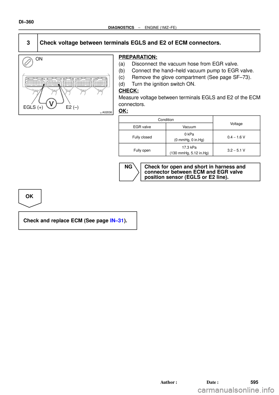
A02036
ON
EGLS (+) E2 (±)
DI±360
± DIAGNOSTICSENGINE (1MZ±FE)
595 Author�: Date�:
3 Check voltage between terminals EGLS and E2 of ECM connectors.
PREPARATION:
(a) Disconnect the vacuum hose from EGR valve.
(b) Connect the hand±held vacuum pump to EGR valve.
(c) Remove the glove compartment (See page SF±73).
(d) Turn the ignition switch ON.
CHECK:
Measure voltage between terminals EGLS and E2 of the ECM
connectors.
OK:
ConditionVltEGR valveVacuumVoltage
Fully closed0 kPa
(0 mmHg, 0 in.Hg)0.4 ~ 1.6 V
Fully open17.3 kPa
(130 mmHg, 5.12 in.Hg)3.2 ~ 5.1 V
NG Check for open and short in harness and
connector between ECM and EGR valve
position sensor (EGLS or E2 line).
OK
Check and replace ECM (See page IN±31).
Page 2781 of 4770
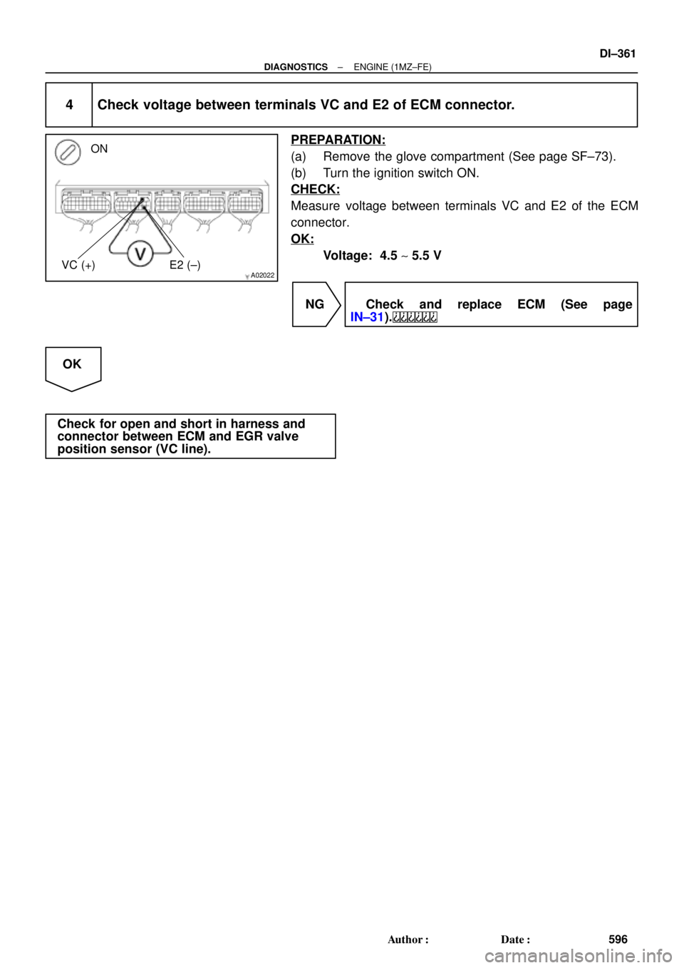
A02022
ON
VC (+) E2 (±)
± DIAGNOSTICSENGINE (1MZ±FE)
DI±361
596 Author�: Date�:
4 Check voltage between terminals VC and E2 of ECM connector.
PREPARATION:
(a) Remove the glove compartment (See page SF±73).
(b) Turn the ignition switch ON.
CHECK:
Measure voltage between terminals VC and E2 of the ECM
connector.
OK:
Voltage: 4.5 ~ 5.5 V
NG Check and replace ECM (See page
IN±31).
OK
Check for open and short in harness and
connector between ECM and EGR valve
position sensor (VC line).